Person Tracking Association Using Multi-modal Systems
A. Belmonte-Hernández , V. Solachidis , T. Theodoridis , G. Hernandez-Peñaloza , G. Conti ,
N. Vretos , F. Alvarez and P. Daras
Abstract
In this paper, a novel multi-modal method for person identification in indoor environments is presented. This ap-proach relies on matching the skeletons detected by a Kinect
v2 device with wearable devices equipped with inertial sen-sors. Movement features such as yaw and pitch changes are employed to associate a particular Kinect skeleton to a person using the wearable. The entire process of sensor cal-ibration, feature extraction, synchronization and matching is detailed in this work. Six detection scenarios were de-fined to assess the proposed method. Experimental results
have shown a high accuracy in the association process.
1. Introduction
Formally, the person identification problem arises when a target (object / person) must be tracked and matched with a specific identity. This target can not be always monitored, however, it must be identified whenever possible. This problem is common in visual monitoring systems where the goal is to individualize targets that can be lost due to oc-clusions, lighting, etc. [3, 1]. In case the object is lost and detected again (by the same camera or a different one), the system must be able to determine that the new tracked ele-ment is the same to the one previously tracked.
The general approach to deal with this problem relies on the extraction of several features from the detected ob-ject. Some examples include RGB-based features such as
color, shape, or texture [1,8]; appearance features incorpo-rate histogram, graph model, spatial occurrence model [3]; whereas biometric features comprise face patterns recogni-tion and gait analysis [7, 10]. These features allow to de-scribe a person and consequently match them with the one with the most similar detected elements.
This problem has attracted the focus of the scientific community due to its usefulness for a wide range of ap-plications in which human activity recognition is required
[11]. However, there exist several scenarios where visual features can not be directly employed due to privacy issues. Therefore, an alternative to camera-based systems is needed [5,13,2]. The use of depth sensors allows information anal-ysis from infrared, skeletons, etc, which has opened a new scope in this research topic [10, 12].
Furthermore, due to the emergence of the use of wire-less sensing technologies, human activity and health status can be easily monitored and analyzed [12, 2]. As a result, such systems can provide useful information in real-time not only to the user himself, but also to the user's carer or doctor, since these technologies have been also adopted in health-related applications as well.
A widespread type of devices employed in such applica-tions are sensor equipped Bracelets. The main use of these devices is for sports and activity tracking, and are usually equipped with DVIU (Inertial Measurement Units) sensors that provide 3D acceleration and 3D angular velocity (gy-roscope) information of the person's movement, and calcu-late steps, distance, calories etc. However, some of them are also equipped with health-related sensors that can ac-quire heart beat rate, body temperature and galvanic skin response.
to systematic records kept by the patient. Second, since the system will be able to alert the patient’s caregiver in case of emergency, patient autonomy will be extended.
In this paper, a method for person individualization us-ing skeleton information from Kinect v2 devices along with smart-wearables is described. This approach relies on the matching of movement features extracted from both de-vices. In section 2, the related work and main contributions are provided. In section 3, the process of feature extraction as well as the main components of the proposed system are detailed. Section 4 shows the experiments performed and the obtained results. Finally, section 5 contains the conclu-sions and future work.
2. Related work
Several works have been proposed in the literature to tackle the person re-identification problem using visual sen-sors [1], and extracting RGB-related features such as color, shape and texture [3].
Furthermore, proposals address this problem by using multiple cameras to extract the main visual features to be compared with the ones obtained by the other cameras [13]. Also, an important research effort has been dedicated to the extraction of features using visual depth sensors [8, 10].
Moreover, there exist approaches for re-identification us-ing information from wireless devices such as smart-phones and wearables [5, 2]. Probably, the most similar work to the one presented here is [12]. In that paper, acceleration features are extracted from Bracelets and compared with the values obtained from depth cameras. However, in our method, orientation information is considered too, which can provide a more comprehensive representation of the performed actions, and therefore increase the accuracy of the identification process. Furthermore, the work presented is a particular case of the general re-identification problem, as the main aim is to individualize and identify persons wearing the bands and detected by the Kinect sensor.
The main contribution of this work is to provide a novel approach for dealing with the person individualization prob-lem in monitoring systems, by using information from mul-tiple sensors.
3. Proposed method
In this work, an indoor environment is considered, where a Kinect v2 sensor is deployed to detect and track people us-ing only skeleton information extracted from depth images. As aforementioned, visual features are not employed, as the work presented is part of a project where privacy issues are critical (further details in Acknowledgments).
The problem addressed in this paper is the individual-ization and route extraction (tracking) of people in a room by associating measurements gathered from diverse data
sources (Kinect depth and wearables). For this purpose, several assumptions have been made:
• People will be identified and tracked within the
cover-age range of depth sensor.
• Association will be performed for up to 6 skeletons
(from 0 to 5) with the corresponding Bracelets (from 1 toN).
• People not wearing Bracelets (i.e. detected only by
Kinect) will not be associated. Analogously, data of people wearing Bracelets but not detected by Kinect will not be considered in the association process.
• It is assumed that a person is wearing a single Bracelet.
• All measurements are synchronized. A specific tool
that gathers and synchronizes data has been developed for this purpose.
Let assume that there are P individuals in a room. Some of them wear Bracelets, thus there are N < P Bracelets. Also, D < 6 skeletons are detected from Kinect, result-ing in 2 • D wrist joints to consider; we are not aware if the Bracelet is worn on the left or the right hand. Two ap-proaches are proposed in this work for matching the sig-nals from the two types of sensors. The first one matches the wrist Pitch extracted from both hands of the detected skeletons with the corresponding Pitch calculated from the Bracelets. The second method employs the Yaw informa-tion of the skeletons chest point and the estimated Yaw from the Bracelet sensors. In the next subsections, details regard-ing the calculation of these features (wrist Pitch and Yaw) for both sensors, data analysis and matching are presented.
3.1. Bracelet
It is assumed that the Bracelets employed can provide 3D acceleration and 3D angular velocity information. How-ever, two important issues regarding these values must be taken into account:
• The coordinate system of the Bracelets is local, and
therefore continuously changing. (I1)
• The gravity vector (which always points towards the
earths center) is part of the returned acceleration values (I2). Namely, the acceleration values provided by the IMUs are equal to the vector sum of the acceleration due to the person’s movement and the gravity force.
3.2. Kinect
human body are provided. Initially, the skeleton joints are filtered using the Tobit-Kalman filter [4]. This is quite an important step, since the extracted skeleton often contains small erratic movements that significantly affect further cal-culations.
3.2.1 Calibration
According to II, values extracted from the Bracelets and the Kinect skeletons can not be directly compared. As aforementioned, the coordinate system of the former is al-ways changing according to the movement / orientation of the Bracelet sensor, while the latter uses a fixed coordinate system, which, however, also depends on the placement / Yaw of the sensor. As a result, the measured acceleration vectors differ between the Bracelet and the Kinect. Even trying to compare the magnitude of the acceleration val-ues (Jax + a?y + a?z), which is more robust since
magni-tude does not depend on the sensor orientation, would not be accurate due to 12. The reason is that the gravity force influences the Bracelet acceleration values. The direct re-moval (or addition) of the gravity force from the Bracelet (to Kinect) would not be a solution, since these processes will be performed in two different coordinate systems. Thus, in order to be able to compare the sensor outputs, a common coordinate system must be constructed as reference.
Bracelet calibration The Bracelet calibration method presented in [6] has been adopted, which estimates the ori-entation of the Bracelet by employing the information gath-ered by accelerometer and gyroscope. The output of this method is the orientation of the Bracelet device in relation to the starting point (initial location of the Bracelet). This information allows the elimination of gravity from acceler-ation measurements.
There are several parameters provided as a result of ap-plying the calibration process. Some of these values in-volve the declination and the gyroscope ¡3, which depend directly on the sensor technical specifications.
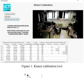
Kinect calibration Kinect has its own coordinate system. Its origin is located at the center of the IR sensor while X axis grows to the sensor’s left, Y axis grows upwards and Z axis to the direction the sensor is facing. Thus, the Kinect coordinate system depends on the custom device setup. In order to calibrate the device, a Calibration tool has been created (Figure 1). In this software, the user selects a set of points (usually 6-10) and sets their coordinates in the de-sired coordinate system. Thus, it is possible to set the Z axis of the new coordinate system to be perpendicular to the ground, and the XY plane to identify with the floor plane. The Calibration tool can retrieve the coordinates of the se-lected points on the Kinect coordinate system and then
cal-Figure 1. Kinect calibration tool
Figure 2. Pitch calculation
culate a transformation between these two coordinate sys-tems. In this tool, the coordinates in both systems are given in centimeters, thus the required transformation is a transla-tion and a rotatransla-tion (no scaling is required). For the rotatransla-tion and translation matrices calculation, the Singular Value De-composition (SVD) of the covariance matrix of the coordi-nates of the two systems is employed.
3.3. Feature calculation
In this section, the aforementioned features will be cal-culated from both Bracelet and Kinect devices. The fol-lowing notation will be used for the vectors: md a where
m G {p, v, a, g} denotes the measurement (^position, v: velocity, a: acceleration, g: angular acceleration), d G {b,k(j)} the device (6: Bracelet, k: Kinect, j : joints in-dex), a G {x, y, z} the axis and c denotes that the vector is on the calibrated space. Hence, the Bracelet provides the ac-celeration ab¡x, ab¡y, a6jZ and gyroscope gbx, gby, gbz
vec-tors from which the bracelet orientation is calculated (given in quaternions Qi: i = 1,2,3,4) that is used to extract the
linear acceleration a ^ a ^ y,arbz in the calibrated space.
JM-í) N Bracelets
5 ) Skeletons
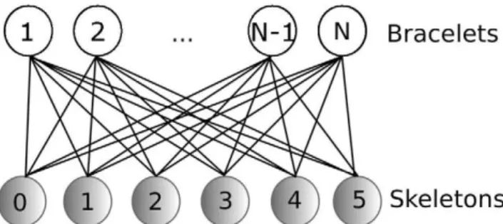
Figure 3. Bipartite graph representing the association links of the N Bracelets with the available skeletons
3.3.1 Wrist pitch
In Kinect case, the wrist pitch can be calculated from the wrist and elbow coordinates. Assuming (Figure 2) that the elbow is the point O and the wrist the point A, then the pitch is the angle 9 equals t a n- 1 (AB/OB). Since
OB = \/CB2 + BD2, 9 = t&n~ 1(AB/\/CB2 + BD2).
Taking into account that AS = p^6I10N Z—pk(5\9) z, BC =
and BD = pf — pi , then
k(6\W),z
pfc(6|10) y ~ pfc(5|9) y a n d Ü U = pfc(6|10) x ~ pfc(5|9) x
the wrist pitch 9¡ir for the left and right wrist is given by:
θl|r = t a n- i
-^l\r,z
l\r,y
(1)
where d is the distance between the wrist and elbow for each pck(5),a and dr,a = p fc(ll),a
axis, namely d¡^a = p^g-, a
pfc(io),¿, a e {xiViz}.
The Bracelet based wrist pitch estimation can be per-formed by employing the Bracelet orientation. By using the orientation quaternions and following the same proce-dure with the Kinect case, it is possible to apply a similar equation with (1) namely
θ = t a n- 1
(
<?3 \
Qi + QÍJ
(2)
where Qi are the quaternion elements of the Bracelet
orien-tation.
3.3.2 Orientation extraction and comparison
As previously mentioned, tools implemented in [6] allow to extract the Yaw, Pitch and Roll features from IMU sen-sors. According to Madgwick filter, the Yaw is calculated as follows:
Yaw = arctan 2(Q2 • Q3 + Q1 • QA),
QI+Q2-Q3- Qif
(3)
where Q denotes the quaternion parameters as previously described in section 3.2.1. The outcome of this filter is the
route in terms of orientation (Yaw), which indicates how much the person has turned around over the detected time.
However, Yaw values are relative to the initial orienta-tion of the device; in this case the Bracelets. Therefore, the result of this filter is the angle between the current and the initial position around the yaw (z) axis, and not between the current position and the magnetic north.
For the Kinect orientation calculation, a central skele-ton joint is selected (i.e. the 20-th that corresponds to the chest). The orientation of the line segment defined by the consecutive chest joint coordinates (-P^o) x-> -^£-(20) ) and (-^fc(20) x'^kfw) ) at times t and t + 1 respectively, cor-responds to the Yaw of the person (Figure 2) in the Kinect fixed coordinate system.
As a consequence, the association process consists in searching for similar orientation routes among the Bracelets and Kinect skeletons.
Let Yb(t) and Y]. (t) be the extracted Yaw sequences from Bracelet and Kinect device respectively. If both are extract from the same person, we expect Yb(t) ~ Yk (t) + s, where
s represents the angle difference between the two coordi-nate systems (Kinect coordicoordi-nate system and Bracelet initial Yaw). In order to eliminate s, instead of comparing the ex-tracted Yaw sequences, we compare their first order deriva-tives, namely the dyb(t)/dt and dyk{t)/dt. As a result, if
both Yaw sequences are extracted from the same person, dyb(t)/dt ~ dyk{t)/dt.
Data association Process The association process is per-formed using the Hungarian algorithm [9]. It computes a complete matching of the bipartite graph (Figure 3), such that the total error of the matched elements is minimized.
The link weights are a combination of the MSEs ob-tained for every feature. Therefore:
Cij = yepitch(ij) + eYaw(iJ) (4)
The cost for each link is given by the Mean Square Er-ror (MSE) for both pitch and orientation. As a result, the combination of Bracelets with the skeletons is obtained. A modification of the standard algorithm was performed, in order to avoid multiple choices for a particular skeleton.
The proposed modified Hungarian algorithm contains the following two additional rules:
Condition 1 If in any step a Bracelet has the minimum cost for more than one Kinect skeleton, the algorithm will asso-ciate the one with the lesser error and remove it. Similarly, in case of having a Kinect skeleton with a minimum cost for several bands, the algorithm will chose the one with the lesser error and will remove it from the list.
ÍO 1 5 2 0 2 5 3 0 3 5 4 0 4 5
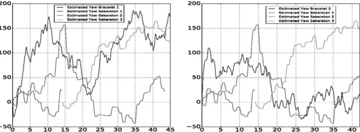
Figure 4. Example of Yaw variation over time for both sensors. This case corresponds to the episode 3 described in section 4. On the left, the MSBand (blue) matches with the cyan skeleton. On the right hand, the other MSBand in the experiment matches with the red Skeleton. Notice that the green and cyan lines correspond to the same person whose skeleton was lost and recovered again.
The former condition is put in place to avoid multiple se-lections of a single skeleton for a Bracelet candidate. The latter, aims to avoid associating a skeleton with a Bracelet, even if algorithm yields this result, because the error is large. The threshold is empirically obtained and depends on the time-window chosen. For the experiments consid-ered in this work, the time-window was 1 minute and the threshold was set to 2500.
The steps for the implementation of the proposed algo-rithm are described as follows:
Calibration process of sensors
1: Calibration of Bracelets as shown in 3.2.1 2: Calibration of Kinect Sensor as shown in 3.2.1
Feature Extraction
3: Orientation calculation from Kinect as presented in sec-tion 3.3.2
4: Orientation calculation from Bracelets as described in section 3.3.2
5: Association of Bracelet-skeleton as described in section 3.3.2
4. Experimental results
In this section, the results of the experiments with the proposed algorithms are detailed. A commercial band de-veloped by Microsoft was employed as wrist device. Ac-cording to the technical specifications, this band is able to provide 8 , 31 or 62 measurements per second. This device is denoted as MSband.
Furthermore, a Kinect sensor was deployed in the moni-tored room at a height of 250cm. The experiment was per-formed under two lighting conditions in order to force the
Kinect device into both available frame rates (15 and 30 fps).
Regarding device synchronization, differences between the unsynchronized sensor timestamps varied up to 500ms and the obtained MSE from the synchronized and unsyn-chronized data were up to a 10% higher. These observations demonstrate that device synchronization is essential for ac-curate results.
To test the feasibility of the proposed algorithms, the fol-lowing episodes were proposed:
• Epi1: A person is detected by the Kinect sensor (skele-ton), the person walks for a while and afterwards leaves the room.
• Epi2: A person is detected by the Kinect sensor (skele-ton), suddenly the tracker loses the person, and after a while it re-detects the person.
• Epi3: Two people are detected by the Kinect sensor (skeleton), and both wear Bracelets. They walk for a while fully detected by Kinect, and then they go out of the scene.
• Epi4: Two individuals are detected by the Kinect sen-sor (skeleton), but only one of them is wearing a Bracelet.
• Epi5: Two people are detected by the Kinect sensor (skeleton), both wearing Bracelets. Suddenly, one of them is lost by Kinect and after a while the person is re-detected.
Table 1. Information about the recorded sessions (in parenthesis the number of people wearing Bracelet)
id 1 2 3 4 5 6
Duration 60 60 45 35 90 35
# of people / skeletons 1 ( 1 ) / 1 2 (0) / 3 2 ( 2 ) / 4 2 ( 1 ) / 3 3 (2) / 7 3 (2) / 5
Pitch Yaw 1 1 3 3 3 4 2 3 6 6 1 3
The Kinect sensor was calibrated so that the XY plane matches the room floor. Sessions of various durations have been recorded in which (2-3) people were present on each one. In Table 1 information about the recorded sessions is presented. More specifically, the episode id, the duration in seconds and the number of people / unique skeleton tracks that Kinect was able to detect are shown. In some sessions, the number of skeleton tracks is higher than the number of people, since some people have been re-detected due to oc-clusions. Finally, the last two columns on the right 1 contain the successful detections for the two methods. It can be ob-served that both of these methods achieve a high matching accuracy.
An example matching using the (Yaw) orientation for two individuals is shown in Figure 4. The vertical axis rep-resents the Yaw and the horizontal axis the time. This par-ticular graphic represents the Epi3 recording. On the left side, after the green skeleton is lost and re-detected as cyan, it can be seen that the Bracelet time-series (blue) follows closely the cyan skeleton, which is the correct match. Sim-ilarly, on the right side, the time-series of the other Bracelet (blue) closely follows the red skeleton, which is again the correct match. The entire dataset with the information of the sensors, calibration and results shown in this paper is avail-able at http://www.gatv.ssr.upm.es/˜abh/
5. Conclusions
In this paper, two approaches that identify a person in an indoor environment using movement features from multiple sensors have been presented. The methods rely on the ex-traction and association of Pitch and Yaw orientation from Bracelets and Kinect. Experimental results have shown the validity of both approaches. As a future work, it will be in-teresting to evaluate the scalability of the system in crowded and large-scale scenarios, as well as to explore the inclusion of sensors such as WSN (Wireless Sensor Network) track-ing systems, which can significantly increase the accuracy and range of the presented algorithms.
Acknowledgement
This work was supported by the European Project: ICT4LIFE http://ict4life.eu/ Grant no. 690090 within the
H2020 Research and Innovation Programme.
References
[1] J. Garca, N. Martinel, G. L. Foresti, A. Gardel, and C. Mich-eloni. Person orientation and feature distances boost re-identification. In 2014 22nd International Conference on
Pattern Recognition, 2014.
[2] K. Koide and J. Miura. Person identification based on the matching of foot strike timings obtained by lrfs and a smart-phone. In 2016 IEEE/RSJ International Conference on
In-telligent Robots and Systems (IROS), 2016.
[3] K. Liu, Z. Zhao, and A. Cai. Parametric local multi-modal metric learning for person re-identification. In 2014 22nd
International Conference on Pattern Recognition, 2014.
[4] K. Loumponias, N. Vretos, P. Daras, and G. Tsaklidis. Us-ing tobit kalman filterUs-ing in order to improve the motion recorded by microsoft kinect. In Proceedings of the
Inter-national workshop on applied probability IWAP 2016, 2016.
[5] T. K. H. I. M Shiomi, M Kurumizawa and N. Hagita. Find-ing a person with a wi-fi device in a crowd of pedestrians.
Advanced Robotics, 2014.
[6] S. O. Madgwick, A. J. Harrison, and R. Vaidyanathan. Esti-mation of imu and marg orientation using a gradient descent algorithm. In Rehabilitation Robotics (ICORR), 2011 IEEE
International Conference on, 2011.
[7] A. Mignon and F. Jurie. Pcca: A new approach for distance learning from sparse pairwise constraints. In IEEE
Confer-ence on Computer Vision and Pattern Recognition, 2012.
[8] A. Mgelmose, C. Bahnsen, T. B. Moeslund, A. Clapes, and S. Escalera. Tri-modal person re-identification with rgb, depth and thermal features. In 2013 IEEE Conference on
Computer Vision and Pattern Recognition Workshops, 2013.
[9] K. Nedas. Implementation of munkres-kuhn (hungarian) al-gorithm. 2005.
[10] F. Pala, R. Satta, G. Fumera, and F. Roli. Multimodal person reidentification using rgb-d cameras. IEEE Transactions on
Circuits and Systems for Video Technology, 2016.
[11] G. Papadopoulos and P. Daras. Human action recognition using 3d reconstruction data. IEEE Transactions on Circuits
and Systems for Video Technology, 2017.
[12] M. Shiomi and N. Hagita. Finding a person with a wearable acceleration sensor using a 3d position tracking system in daily environments. Advanced Robotics, 2015.
[13] W. S. Zheng, S. Gong, and T. Xiang. Reidentification by relative distance comparison. IEEE Transactions on Pattern