DIPLOMADO DE PROFUNDIZACION CISCO PRUEBA DE HABILIDADES PRÁCTICAS CCNP
MAIRA YORELLY CARDOZO PENAGOS
UNIVERSIDAD NACIONAL ABIERTA Y A DISTANCIA - UNAD ESCUELA DE CIENCIAS BÁSICAS, TECNOLOGÍA E INGENIERÍA – ECBTI
INGENIERÍA ELECTRÓNICA MADRID
DIPLOMADO DE PROFUNDIZACION CISCO PRUEBA DE HABILIDADES PRÁCTICAS CCNP
MAIRA YORELLY CARDOZO PENAGOS
Diplomado de opción de grado presentado para optar el título de INGENIERA ELECTRÓNICA
DIRECTOR:
MSc. GERARDO GRANADOS ACUÑA
UNIVERSIDAD NACIONAL ABIERTA Y A DISTANCIA - UNAD ESCUELA DE CIENCIAS BÁSICAS, TECNOLOGÍA E INGENIERÍA – ECBTI
INGENIERÍA ELECTRÓNICA MADRID
NOTA DE ACEPTACIÓN
Firma del Presidente del Jurado
_______________________ Firma del Jurado
_______________________ Firma del Jurado
TABLA DE CONTENIDO
Contenido
LISTA DE TABLAS ... 5
LISTA DE ILUSTRACIONES ... 6
GLOSARIO ... 7
RESUMEN ... 8
ABSTRACT ... 9
INTRODUCCIÓN ... 10
ESCENARIO 1... 11
Parte 1: Configuración del escenario propuesto ... 12
Parte 2: Verificar conectividad de red y control de la trayectoria... 18
ESCENARIO 2... 19
Parte 1: Configurar la red de acuerdo con las especificaciones... 20
Part 2: conectividad de red de prueba y las opciones configuradas... 42
CONCLUSIONES ... 48
LISTA DE TABLAS
LISTA DE ILUSTRACIONES
Ilustración 1 Topología de red escenario 1 ... 11
Ilustración 2 Diseño escenario 1 en Packet Tracer ... 12
Ilustración 3 Configuración del escenario en Packet Tracer ... 15
Ilustración 4: Ping R2 A R3 Y R1 ... 18
Ilustración 5: Ping R1 a R2 y R3 ... 18
Ilustración 6 Topología de red escenario 2 ... 19
Ilustración 7 Diseño escenario 2 en Packet Tracer ... 19
Ilustración 8 Configuracion en Packet Tracer ... 26
Ilustración 9 Configuración Host A ... 40
Ilustración 10 Configuración Host B ... 41
Ilustración 11 Configuración Host C ... 41
Ilustración 12 Configuración Host D ... 41
Ilustración 13 Existencia de las VLAN en DLS1 ... 42
Ilustración 14 Existencia de las VLAN en DLS2 ... 42
Ilustración 15 Existencia de las VLAN en ALS1 ... 43
Ilustración 16 Existencia de las VLAN en ALS2 ... 43
Ilustración 17 Correcta donfiguracion del EtherChannel en DLS1 ... 44
Ilustración 18 Correcta donfiguracion del EtherChannel en ALS1 ... 44
Ilustración 19 Configuración de Spanning tree en DLS1 ... 45
Ilustración 20 Configuración de Spanning tree en DLS2 ... 45
Ilustración 21 Configuraciones HSRP ... 46
Ilustración 22 Configuracion DSL1 VLAN Principal ... 46
GLOSARIO
CCNP: (Cisco Certified Network Professional) Nivel intermedio de certificación de la compañía CISCO, con los temas de enrutamiento, conmutación y resolución de problemas.
CONMUTACIÓN: Establecer una via o un camino entre dos puntos.
ENRUTAMIENTO: Es la función de un camino entre todos los posibles en una red de paquetes cuyas topologías poseen una gran conectividad.
GNS3: Simulador grafico que permite diseñar topologías de red con sus respectivas simulaciones.
PACKET TRACER: Herramienta interactiva de aprendizaje tanto para instructores como para alumnos que permite la simulación de redes.
PROTOCOLOS DE RED: Donde se designan un conjunto de reglas que rigen el intercambio de información por medio de una red.
REDES: Conjunto de equipos entre computadoras y dispositivos conectados por medio de cables, señales, ondas y cualquier otro medio de transporte para compartir información condicionada.
RESUMEN
La Universidad Nacional Abierta y a Distancia UNAD brinda la oportunidad a los estudiantes por medio de CISCO de realizar el diplomado de profundización CCNP como opción de grado y a la vez enriquecer el conocimiento en el área de las telecomunicaciones. En la actualidad las redes y la comunicación juegan un papel muy importante en el mundo, abarcando diversos entornos; aprender y conocer el funcionamiento de esta área permite desenvolvernos en un campo más amplio de la ingeniería.
El aprendizaje y los logros del diplomado CISCO: diseño e implementación de redes LAN-WAN se evidencia en el trabajo a realizar, donde se muestran las competencias adquiridas durante el proceso de aprendizaje, mediante dos escenarios a desarrollar.
ABSTRACT
The National Open and Distance University (UNAD acronym in Spanish) provides the opportunity for students through CISCO to complete the CCNP deepening diplomat as a degree option and at the same time enrich knowledge in the area of telecommunications. Currently, networks and communication will have a very important role in the world, covering different environments; Learning and knowing how these area works allow us to develop in a broader field of engineering.
The learning and achievements of the CISCO diplomat: The design and implementation of LAN-WAN networks are evident in the work to be performed, where the skills acquired during the learning process are developed, through two scenarios to be developed.
INTRODUCCIÓN
La prueba de habilidades practicas CCNP pretende evaluar el nivel de desarrollo de competencias y habilidades que fueron obtenidas durante la realización del diplomado por medio de la solución de dos escenarios propuestos que se deben trabajar en todos los aspectos ya vistos anteriormente.
ESCENARIO 1
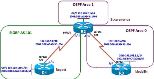
Una empresa de confecciones posee tres sucursales distribuidas en las ciudades de Bogotá, Medellín y Bucaramanga, en donde el estudiante será el administrador de la red, el cual deberá configurar e interconectar entre sí cada uno de los dispositivos que forman parte del escenario, acorde con los lineamientos establecidos para el direccionamiento IP, protocolos de enrutamiento y demás aspectos que forman parte de la topología de red.
Topología de red:
Desarrollo:
Ilustración 2 Diseño escenario 1 en Packet Tracer
Configurar la topología de red, de acuerdo con las siguientes especificaciones.
Parte 1: Configuración del escenario propuesto
1. Configurar las interfaces con las direcciones IPv4 e IPv6 que se muestran en la topología de red.
Configuración de las interfaces: Configuración R1
Router>ena Router#confi term
Enter configuration commands, one per line. End with CNTL/Z. Router(config)#hostname R1
R1(config)#interface gigabitEthernet 0/0
R1(config-if)#ip address 192.168.110.1 255.255.255.0 R1(config-if)#ipv6 address 2001:DB8:ACAD:110::1/64 R1(config-if)#NO SHUTdown
R1(config-if)#
%LINK-5-CHANGED: Interface GigabitEthernet0/0, changed state to up %LINEPROTO-5-UPDOWN: Line protocol on Interface GigabitEthernet0/0, changed state to up
R1(config-if)#EXIT
R1(config)#INterface Serial 0/0/0
R1(config-if)#IP ADdress 192.168.9.1 255.255.255.252 R1(config-if)#IPV6 ADdress 2001:DB8:ACAD:90::1/64 R1(config-if)#NO SHUtdown
R1(config)#%LINEPROTO-5-UPDOWN: Line protocol on Interface Serial0/0/0, changed state to up
R1(config)#EXIT
R1#%SYS-5-CONFIG_I: Configured from console by console R1#W Building configuration... [OK] R1# Configuración R2 R2>ENA R2#CONFI TERMI
Enter configuration commands, one per line. End with CNTL/Z. R2(config)#HOStname R2
R2(config)#interface gigabitEthernet 0/0
R2(config-if)#ip address 192.168.2.1 255.255.255.0 R2(config-if)#ipv6 address 2001:DB8:ACAD:B::1/64
%GigabitEthernet0/0: Error: 2001:DB8:ACAD:B::/64 is overlapping with 2001:DB8:ACAD:B::/64 on Serial0/0/0
R2(config-if)#NO SHUTdown R2(config-if)#EXIT
R2(config)#INTerface Serial 0/0/0
R2(config-if)#IP ADdress 192.168.9.2 255.255.255.252 R2(config-if)#IPV6 ADdress 2001:DB8:ACAD:90.2/64 % Incomplete command.
R2(config-if)#IPV6 ADdress 2001:DB8:ACAD:90::2/64 R2(config-if)#NO SHUTdown
R2(config-if)#EXIT R2(config)#EXIT
R2#%SYS-5-CONFIG_I: Configured from console by console R2#W
Building configuration... [OK]
R2#
R2(config)#INTerface S
R2(config)#INTerface Serial 0/0/1
R2(config-if)#IP ADdress 192.168.9.5 255.255.255.252 R2(config-if)#IPV6 ADdress 2001:DB8:ACAD:91::1/64 R2(config-if)#NO SHUtdown
%LINK-5-CHANGED: Interface Serial0/0/1, changed state to down R2(config-if)#
R2(config-if)#EXIT R2(config)#END
Configuracion R3 R3>ena
R3#confi term
Enter configuration commands, one per line. End with CNTL/Z. R3(config)#HOStname R3
R3(config)#interface gigabitEthernet 0/0 R3(config-if)#ip ad
R3(config-if)#ip address 192.168.3.1 255.255.255.0 R3(config-if)#ipv6 address 2001:DB8:ACAD:C::1/64 R3(config-if)#NO SHUtdown
R3(config-if)#
%LINK-5-CHANGED: Interface GigabitEthernet0/0, changed state to up %LINEPROTO-5-UPDOWN: Line protocol on Interface GigabitEthernet0/0, changed state to up
R3(config-if)#EXIT
R3(config)#INTerface Serial 0/0/1
R3(config-if)#IPV 192.168.9.6 255.255.255.252 R3(config-if)#IPV A 192.168.9.6 255.255.255.252 R3(config-if)#IPV A 192.168.9.6 255.255.255.252D R3(config-if)#IP AD 192.168.9.6 255.255.255.252 R3(config-if)#IP ADD 192.168.9.6 255.255.255.252 R3(config-if)#IP address 192.168.9.6 255.255.255.252 R3(config-if)#ipv6 address 2001:DB8:ACAD:91::2/64 R3(config-if)#NO SHUtdown
R3(config-if)#%LINK-5-CHANGED: Interface Serial0/0/1, changed state to up R3(config-if)#%LINEPROTO-5-UPDOWN: Line protocol on Interface Serial0/0/1, changed state to up
R3(config-if)#EXIT R3(config)#EXIT
R3#%SYS-5-CONFIG_I: Configured from console by console R3#W
Ilustración 3 Configuración del escenario en Packet Tracer
2. Ajustar el ancho de banda a 128 kbps sobre cada uno de los enlaces seriales ubicados en R1, R2, y R3 y ajustar la velocidad de reloj de las conexiones de DCE según sea apropiado.
Para R1
R1(config)#INTerface Serial 0/0/0 R1(config-if)#clock rate 128000 R1(config-if)#bandwidth 128 R1(config-if)#no sh
R1(config-if)#no shutdown R1(config-if)#exit
R1(config)#
Para R2
R2(config)#INTerface Serial 0/0/0 R2(config-if)#BAndwidth 128
R2(config-if)#EXIT R2(config)#EXIT
R2(config)#INTerface Serial 0/0/1 R2(config-if)#CLOC R
R2(config-if)#CLOC Rate 128000 R2(config-if)#BA
R2(config-if)#BAndwidth 128 R2(config-if)#EXIT
R2(config)#
Para R3
R3(config-if)#b
R3(config-if)#bandwidth 128 R3(config-if)#exit
R3(config)#
3. En R2 y R3 configurar las familias de direcciones OSPFv3 para IPv4 e IPv6.
Utilice el identificador de enrutamiento 2.2.2.2 en R2 y 3.3.3.3 en R3 para ambas familias de direcciones.
Para R2
R2(config)#router ospf 1 R2(config-router)#router
R2(config-router)#router-id 2.2.2.2 Para R3
R3(config)#router ospf 1 R3(config-router)#router
R3(config-router)#router-id 3.3.3.3
4. En R2, configurar la interfaz F0/0 en el área 1 de OSPF y la conexión serial entre R2 y R3 en OSPF área 0.
En R2
R2(config)#router ospf 1 R2(config-router)#router
R2(config-router)#router-id 2.2.2.2
R2(config-router)#network 192.168.9.0 0.0.0.3 area 1 R2(config-router)#network 192.168.2.0 0.0.0.255 area 1
R2(config-router)#exit
5. En R3, configurar la interfaz F0/0 y la conexión serial entre R2 y R3 en OSPF área 0.
En R3
R3#confi term
Enter configuration commands, one per line. End with CNTL/Z. R3(config)#router ospf 1
R3(config-router)#router
R3(config-router)#network 192.168.9.4 0.0.0.3 area 1 R3(config-router)#net
R3(config-router)#network 192.168.3.0 0.0.0.255 area 1 R3(config-router)#exit
6. Configurar el área 1 como un área totalmente Stubby. R2>ena
R2# confi term
Enter configuration commands, one per line. End with CNTL/Z. R2(config)#router ospf 1
R2(config-router)#area 1 stub R2(config-router)#exit
R2(config)#
7. Propagar rutas por defecto de IPv4 y IPv6 en R3 al interior del dominio OSPFv3. Nota: Es importante tener en cuenta que una ruta por defecto es diferente a la definición de rutas estáticas. 8. Realizar la configuración del protocolo EIGRP para IPv4 como IPv6.
Configurar la interfaz F0/0 de R1 y la conexión entre R1 y R2 para EIGRP con el sistema autónomo 101. Asegúrese de que el resumen automático está desactivado.
R1(config)#router eig
R1(config)#router eigrp 101
R1(config-router)#no auto-summary
R1(config-router)#network 192.168.9.0 0.0.0.3 R1(config-router)#network 192.168.110.0 0.0.0.255 R1(config-router)#network 192.168.2.0 0.0.0.255 R1(config-router)#exit
R1(config)#exit
9. Configurar las interfaces pasivas para EIGRP según sea apropiado. 10. En R2, configurar la redistribución mutua entre OSPF y EIGRP para
IPv4 e IPv6. Asignar métricas apropiadas cuando sea necesario.
11. En R2, de hacer publicidad de la ruta 192.168.3.0/24 a R1 mediante una lista de distribución y ACL.
R2(config)#access-list 1 perm 192.168.3.0 R2(config)#access-list 1 perm any
R2(config)#router eigrp 101
Parte 2: Verificar conectividad de red y control de la trayectoria.
a. Registrar las tablas de enrutamiento en cada uno de los routers, acorde con los parámetros de configuración establecidos en el escenario propuesto.
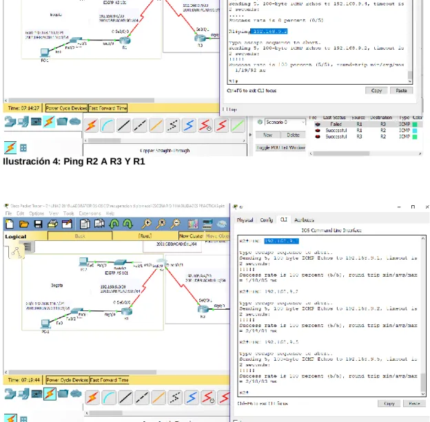
b. Verificar comunicación entre routers mediante el comando ping y traceroute
c. Verificar que las rutas filtradas no están presentes en las tablas de enrutamiento de los routers correctas.
Ilustración 4: Ping R2 A R3 Y R1
ESCENARIO 2
Una empresa de comunicaciones presenta una estructura Core acorde a la topología de red, en donde el estudiante será el administrador de la red, el cual deberá configurar e interconectar entre sí cada uno de los dispositivos que forman parte del escenario, acorde con los lineamientos establecidos para el direccionamiento IP, etherchannels, VLANs y demás aspectos que forman parte del escenario propuesto.
Topología de red:
Diseño en Packet tracer:
Ilustración 7 Diseño escenario 2 en Packet Tracer
Desarrollo:
Parte 1: Configurar la red de acuerdo con las especificaciones. a. Apagar todas las interfaces en cada switch.
DLS1
Switch#configure terminal
Enter configuration commands, one per line. End with CNTL/Z. Switch(config)#hostname DSL1
DSL1(config)#interface range f0/1-24 DSL1(config-if-range)#shutdown
%LINK-5-CHANGED: Interface FastEthernet0/1, changed state to administratively down
DSLI(config-if-range)#exit
DLS2
Switch>enable
Switch#configure terminal
Enter configuration commands, one per line. End with CNTL/Z. Switch(config)#interface range fastEthernet 0/1-24
Switch(config-if-range)#shutdown
%LINK-5-CHANGED: Interface FastEthernet0/1, changed state to administratively down Switch(config)#hostname DLS2 DLS2(config)# ALS1 Switch>enable Switch#configure terminal
Enter configuration commands, one per line. End with CNTL/Z. Switch(config)#hostname ALS1
ALS1(config)#INTerface Range FastEthernet 0/1-24 ALS1(config-if-range)#shutdown
%LINK-5-CHANGED: Interface FastEthernet0/1, changed state to administratively down
ALS1(config-if-range)#exit
ALS2 Switch>ena
Switch#configure terminal
Enter configuration commands, one per line. End with CNTL/Z. Switch(config)#hostname ALS2
ALS2(config)#interface range fastEthernet 0/1-24 ALS2(config-if-range)#shutdown
%LINK-5-CHANGED: Interface FastEthernet0/1, changed state to administratively down
b. Asignar un nombre a cada switch acorde al escenario establecido. DSL1
Switch>enable
Switch#configure terminal
Enter configuration commands, one per line. End with CNTL/Z. Switch(config)#hostname DLS1
DSL2
Switch>enable
Switch#configure terminal
Enter configuration commands, one per line. End with CNTL/Z. Switch(config)#hostname DLS2
ALS1
Switch#configure terminal
Enter configuration commands, one per line. End with CNTL/Z. Switch(config)#hostname ALS1
ALS2
Switch>enable
Switch#configure terminal
Enter configuration commands, one per line. End with CNTL/Z. Switch(config)#hostname ALS2
c. Configurar los puertos troncales y Port-channels tal como se muestra en el diagrama.
1) La conexión entre DLS1 y DLS2 será un EtherChannel capa-3
utilizando LACP. Para DLS1 se utilizará la dirección IP 10.12.12.1/30 y para DLS2 utilizará 10.12.12.2/30.
2) Los Port-channels en las interfaces Fa0/7 y Fa0/8 utilizarán LACP. 3) Los Port-channels en las interfaces F0/9 y fa0/10 utilizará PAgP. 4) Todos los puertos troncales serán asignados a la VLAN 800 como la
VLAN nativa. DLS1
DSL1(config)#interface range f0/11-12 DSL1(config-if-range)#no switchport
DSL1(config-if-range)#channel-group 12 mode active DSL1(config-if-range)#
Creating a port-channel interface Port-channel 12 DSL1(config-if-range)#no shutdown
DSL1(config-if-range)#
DSL1(config)#interface port-channel c DSL1(config)#interface port-channel 12
DSL1(config-if)#ip address 10.12.12.1 255.255.255.252 DSL1(config-if)#exit
DSL1(config)#interface range fastEthernet 0/7-10
DSL1(config-if-range)#switchport trunk encapsulation dot1q DSL1(config-if-range)#switchport trunk native vlan 800 DSL1(config-if-range)#switchport mode trunk
DSL1(config-if-range)#switchport nonegotiate DSL1(config-if-range)#no shutdown
%LINK-5-CHANGED: Interface FastEthernet0/7, changed state to down %LINK-5-CHANGED: Interface FastEthernet0/8, changed state to down %LINK-5-CHANGED: Interface FastEthernet0/9, changed state to down %LINK-5-CHANGED: Interface FastEthernet0/10, changed state to down DSL1(config-if-range)#exit
DSL1(config)#interface range fastEthernet 0/7-8 DSL1(config-if-range)#desc member of po 1 to ALS1 DSL1(config-if-range)#channel-group 1 mode active Creating a port-channel interface Port-channel 1
%EC-5-CANNOT_BUNDLE2: Fa0/7 is not compatible with Po1 and will be suspended (native vlan of Fa0/7 is 800, Po1 id 1)
%EC-5-CANNOT_BUNDLE2: Fa0/8 is not compatible with Po1 and will be suspended (native vlan of Fa0/8 is 800, Po1 id 1)
DSL1(config-if-range)#exit
DSL1(config)#interface range fastEthernet 0/9-10 DSL1(config-if-range)#desc member of po4 to ALS2 DSL1(config-if-range)#channel-group 4 mode desirable Creating a port-channel interface Port-channel 4
DSL1(config-if-range)#exit
DLS2
DLS2>enable
DLS2#configure terminal
Enter configuration commands, one per line. End with CNTL/Z. DLS2(config)#interface range fastEthernet 0/11-12
DLS2(config-if-range)#no switchport
DLS2(config-if-range)#channel-group 12 mode active Creating a port-channel interface Port-channel 12 no sh
DLS2(config-if-range)#no shutdown DLS2(config-if-range)#
%LINK-5-CHANGED: Interface FastEthernet0/11, changed state to up
%LINK-5-CHANGED: Interface FastEthernet0/12, changed state to up
%LINEPROTO-5-UPDOWN: Line protocol on Interface FastEthernet0/12, changed state to up
%LINK-5-CHANGED: Interface Port-channel12, changed state to up
%LINEPROTO-5-UPDOWN: Line protocol on Interface Port-channel12, changed state to up
DLS2(config-if-range)#exit DLS2(config)#in
DLS2(config)#interface port-channel 12
DLS2(config-if)#ip address 10.12.12.2 255.255.255.252 DLS2(config-if)#exit
DLS2(config)#interface range fastEthernet 0/7-10
DLS2(config-if-range)#switchport trunk encapsulation dot1q DLS2(config-if-range)#switchport trunk native vlan 800 DLS2(config-if-range)#switchport mode trunk
DLS2(config-if-range)#switchport nonegotiate DLS2(config-if-range)#no shutdown
%LINK-5-CHANGED: Interface FastEthernet0/7, changed state to down %LINK-5-CHANGED: Interface FastEthernet0/8, changed state to down %LINK-5-CHANGED: Interface FastEthernet0/9, changed state to down %LINK-5-CHANGED: Interface FastEthernet0/10, changed state to down DLS2(config-if-range)#exit
DLS2(config)#interface range fastEthernet 0/7-8 DLS2(config-if-range)#desc member of po1 to ALS2 DLS2(config-if-range)#channel-group 2 mode active Creating a port-channel interface Port-channel 2 DLS2(config-if-range)#exit
DLS2(config)#interface range fastEthernet 0/9-10 DLS2(config-if-range)#desc member of po3 to ALS1 DLS2(config-if-range)#channel-group 3 mode desirable Creating a port-channel interface Port-channel 3
DLS2(config)#
ALS1
ALS1>enable
ALS1#configure terminal
Enter configuration commands, one per line. End with CNTL/Z. ALS1(config)#interface range fastEthernet 0/7-10
ALS1(config-if-range)#switchport trunk native vlan 800 ALS1(config-if-range)#switchport mode trunk
ALS1(config-if-range)#switchport nonegotiate ALS1(config-if-range)#no shutdown
%LINK-5-CHANGED: Interface FastEthernet0/7, changed state to up
%LINK-5-CHANGED: Interface FastEthernet0/8, changed state to up
%LINEPROTO-5-UPDOWN: Line protocol on Interface FastEthernet0/8, changed state to up
%LINK-5-CHANGED: Interface FastEthernet0/9, changed state to up
%LINEPROTO-5-UPDOWN: Line protocol on Interface FastEthernet0/9, changed state to up
%LINK-5-CHANGED: Interface FastEthernet0/10, changed state to up
%LINEPROTO-5-UPDOWN: Line protocol on Interface FastEthernet0/10, changed state to up
ALS1(config-if-range)#exit
ALS1(config)#interface range fastEthernet 0/7-8 ALS1(config-if-range)#desc member of po1 to DLS1 ALS1(config-if-range)#channel-group 1 mode active Creating a port-channel interface Port-channel 1 ALS1(config-if-range)#switchport trunk allowed vlan 12,123,234,800,1010,1111,3456
Command rejected: Bad VLAN list Command rejected: Bad VLAN list ALS1(config-if-range)#no shutdown ALS1(config-if-range)#exit
ALS1(config)#interface range fastEthernet 0/9-10 ALS1(config-if-range)#desc member of po 3 to DLS2 ALS1(config-if-range)#Channel-group 3 mode desirable ALS1(config-if-range)#
Creating a port-channel interface Port-channel 3 ALS1(config-if-range)#switchport trunk allowed vlan 12,123,234,800,1010,1111,3456
Command rejected: Bad VLAN list Command rejected: Bad VLAN list ALS1(config-if-range)#no shutdown ALS1(config-if-range)#exit
ALS1(config)#interface vlan 3456
ALS1(config-if)#ip address 10.34.56.101 255.255.255.0 ALS1(config-if)#no shutdown
ALS1(config-if)#exit
ALS1(config)#ip default-gateway 10.34.56.254 ALS1(config)#exit
ALS1#
%SYS-5-CONFIG_I: Configured from console by console ALS1#wr
Building configuration... [OK]
ALS2#configure terminal
Enter configuration commands, one per line. End with CNTL/Z. ALS2(config)#interface range fastEthernet 0/7-10
ALS2(config-if-range)#switchport trunk native vlan 800 ALS2(config-if-range)#switchport mode trunk
ALS2(config-if-range)#switchport nonegotiate ALS2(config-if-range)#exit
ALS2(config)#interface range fastEthernet 0/7-8 ALS2(config-if-range)#desc member of po2 to DLS2 ALS2(config-if-range)#channel-group 2 mode active Creating a port-channel interface Port-channel 2 ALS2(config-if-range)#switchport trunk allowed vlan 12,123,234,800,1010,1111,3456
Command rejected: Bad VLAN list Command rejected: Bad VLAN list ALS2(config-if-range)#no shutdown ALS2(config-if-range)#
%LINK-5-CHANGED: Interface FastEthernet0/7, changed state to up
%LINEPROTO-5-UPDOWN: Line protocol on Interface FastEthernet0/7, changed state to up
%LINK-5-CHANGED: Interface FastEthernet0/8, changed state to up
%LINEPROTO-5-UPDOWN: Line protocol on Interface FastEthernet0/8, changed state to up
ALS2(config-if-range)#exit
ALS2(config)#interface range fastEthernet 0/9-10 ALS2(config-if-range)#desc member of po 4 to DLS1 ALS2(config-if-range)#channel-group 4 mode desirable Creating a port-channel interface Port-channel 4
ALS2(config-if-range)#switchport trunk allowed vlan 12,123,234,800,1010,1111,3456
Command rejected: Bad VLAN list Command rejected: Bad VLAN list ALS2(config-if-range)#no shutdown ALS2(config-if-range)#exit
ALS2(config)#interface vlan 3456
ALS2(config-if)#ip add 10.34.56.102 255.255.255.0 ALS2(config-if)#no shutdown
ALS2(config-if)#exit
ALS2(config)#ip default-gateway 10.34.56.254 ALS2(config)#exit
%SYS-5-CONFIG_I: Configured from console by console ALS2#wr
Ilustración 8 Configuracion en Packet Tracer
d. Configurar DLS1, ALS1, y ALS2 para utilizar VTP versión 3
1) Utilizar el nombre de dominio UNAD con la contraseña cisco123 2) Configurar DLS1 como servidor principal para las VLAN.
3) Configurar ALS1 y ALS2 como clientes VTP.
VTP en packet tracer DSL1(config)#vtp ver ?
<1-2> Set the adminstrative domain VTP version number DLS1
DSL1>enable
DSL1#configure terminal
Enter configuration commands, one per line. End with CNTL/Z. DSL1(config)#vtp domain UNAD
Changing VTP domain name from SWLAB to UNAD DSL1(config)#vtp ver 3.
DSL1(config)#vtp ver ?
<1-2> Set the adminstrative domain VTP version number DSL1(config)#vtp password cisco123
Setting device VLAN database password to cisco123 DSL1(config)#vtp primary vlan
DSL1(config)#vtp ?
domain Set the name of the VTP administrative domain. mode Configure VTP device mode
password Set the password for the VTP administrative domain version Set the adminstrative domain to VTP version
ALS1
ALS1>enable
ALS1#configure terminal
Enter configuration commands, one per line. End with CNTL/Z. ALS1(config)#vtp domain UNAD
Changing VTP domain name from SWLAB to UNAD ALS1(config)#vtp ver 3
ALS1(config)#vtp ver ?
<1-2> Set the adminstrative domain VTP version number <1-2> Set the adminstrative domain VTP version number ALS1(config)#vtp mode client
Setting device to VTP CLIENT mode. ALS1(config)#vtp password cisco123
Setting device VLAN database password to cisco123 ALS1(config)#exit
ALS1#
%SYS-5-CONFIG_I: Configured from console by console ALS1#
ALS2 ALS2>
ALS2>enable
ALS2#configure terminal
Enter configuration commands, one per line. End with CNTL/Z. ALS2(config)#vtp domain UNAD
Changing VTP domain name from SWLAB to UNAD ALS2(config)#vtp ver 3
ALS2(config)#vtp ver ?
<1-2> Set the adminstrative domain VTP version number ALS2(config)#vtp ver 2
VTP mode already in V2. ALS2(config)#vtp mode client
Setting device to VTP CLIENT mode. ALS2(config)#vtp password cisco123
Setting device VLAN database password to cisco123 ALS2(config)#exit
ALS2#
%SYS-5-CONFIG_I: Configured from console by console ALS2#
e. Configurar en el servidor principal las siguientes VLAN:
Número de VLAN Nombre de VLAN
Número de VLAN
Nombre de VLAN
800 NATIVA 434 ESTACIONAMIENTO
12 EJECUTIVOS 123 MANTENIMIENTO
234 HUESPEDES 1010 VOZ
1111 VIDEONET 3456 ADMINISTRACIÓN
Algunos extenciones de las vlans han sido disminuidas por incapaisdad del
hardware VLAN_CREATE_FAIL: Failed to create VLANs 3456: extended VLAN(s) not allowed in current VTP mode
DLS1
DSL1>enable DSL1#conf term
Enter configuration commands, one per line. End with CNTL/Z. DSL1(config)#host DSL1(config)#hostname DLS1 DLS1(config)#vlan 800 DLS1(config-vlan)#name NATIVA DLS1(config-vlan)#vlan 434 DLS1(config-vlan)#name ESTACIONAMIENTO DLS1(config-vlan)#vlan 12 DLS1(config-vlan)#name EJECUTIVOS DLS1(config-vlan)#vlan 123 DLS1(config-vlan)#name MANTENIMIENTO DLS1(config-vlan)#vlan 234 DLS1(config-vlan)#name HUESPEDES DLS1(config-vlan)#vlan 1010
VLAN_CREATE_FAIL: Failed to create VLANs 1010: extended VLAN(s) not allowed in current VTP mode
f. En DLS1, suspender la VLAN 434. DLS1(config)#vlan 434
DLS1(config-vlan)#state suspend
g. Configurar DLS2 en modo VTP transparente VTP utilizando VTP versión 2, y configurar en DLS2 las mismas VLAN que en DLS1.
DLS2>ena DLS2#confi term
Enter configuration commands, one per line. End with CNTL/Z. DLS2(config)#vtp ver 2
VTP mode already in V2.
DLS2(config)#vtp mode transparent
Setting device to VTP TRANSPARENT mode. DLS2(config)#vlan 800 DLS2(config-vlan)#name NATIVA DLS2(config-vlan)#exit DLS2(config)#vlan 434 DLS2(config-vlan)#name ESTACIONAMIENTO DLS2(config-vlan)#exit DLS2(config)#vlan 12 DLS2(config-vlan)#name EJECUTIVOS DLS2(config-vlan)#exit DLS2(config)#vlan 123 DLS2(config-vlan)#name MANTENIMIENTO DLS2(config-vlan)#exit DLS2(config)#vlan 234 DLS2(config-vlan)#name HUESPEDES DLS2(config-vlan)#exit DLS2(config)#vlan 101 DLS2(config-vlan)#name VOZ DLS2(config-vlan)#exit DLS2(config)#vlan 111 DLS2(config-vlan)#name VIDEONET DLS2(config-vlan)#exit DLS2(config)#vlan 345 DLS2(config-vlan)#name ADMINISTRACION DLS2(config-vlan)#exit DLS2(config)#exit
%SYS-5-CONFIG_I: Configured from console by console DLS2#wr
h. Suspender VLAN 434 en DLS2. DLS2(config)#vlan 434
DLS2(config-vlan)#state suspend
i. En DLS2, crear VLAN 567 con el nombre de CONTABILIDAD. La VLAN
de CONTABILIDAD no podrá estar disponible en cualquier otro Switch de la red.
DLS2(config)#vlan 567
DLS2(config-vlan)#name CONTABILIDAD (config-vlan)#EXIT
DLS2(config)#
j. Configurar DLS1 como Spanning tree root para las VLAN 1, 12, 434, 800, 1010, 1111 y 3456 y como raíz secundaria para las VLAN 123 y 234. DLS1(config)#spanning-tree vlan 1,12,434,800,101,111,345 root primary DLS1(config)#spanning-tree vlan 123,234 root secondary
DLS1(config)#
k. Configurar DLS2 como Spanning tree root para las VLAN 123 y 234 y como una raíz secundaria para las VLAN 12, 434, 800, 1010, 1111 y 3456.
DLS1#configure terminal
Enter configuration commands, one per line. End with CNTL/Z.
DLS1(config)#spanning-tree vlan 1,12,434,800,101,111,345 root primary DLS1(config)#spanning-tree vlan 123,234 root secondary
DLS1(config)#
l. Configurar todos los puertos como troncales de tal forma que solamente las VLAN que se han creado se les permitirá circular a través de éstos puertos.
DLS1
DLS1(config)#interface port-channel 1 DLS1(config-if)#switchport trunk a
DLS1(config-if)#switchport trunk allowed vlan 12,123,234,800,101,111,345 DLS1(config-if)#exit
DLS1(config)#in
DLS1(config)#interface port-channel 4
DLS1(config-if)#switchport trunk allowed vlan 12,123,234,800,101,111,345 DLS1(config-if)#exit
DLS2
DLS2(config-if)#switchport trunk allowed vlan 12,123,234,800,101,111,345 DLS2(config-if)#exit
DLS2(config)#interface port-channel 3
DLS2(config-if)#switchport trunk allowed vlan 12,123,234,800,101,111,345 DLS2(config-if)#exit
DLS2(config)#
m. Configurar las siguientes interfaces como puertos de acceso, asignados a las VLAN de la siguiente manera:
Tabla 2 Interfaces
Interfaz DLS1 DLS2 ALS1 ALS2
Interfaz Fa0/6 3456 12 ,
1010
123, 1010
234
Interfaz Fa0/15 1111 1111 1111 1111
Interfaces F0 /16-18 567
DLS1
DLS1(config)#interface fastEthernet 0/6 DLS1(config-if)#switchport access vlan 345 DLS1(config-if)#no shutdown
%LINK-5-CHANGED: Interface FastEthernet0/6, changed state to up
%LINEPROTO-5-UPDOWN: Line protocol on Interface FastEthernet0/6, changed state to up
DLS1(config-if)#exit
DLS1(config)#interface fastEthernet 0/15 DLS1(config-if)#switchport access vlan 111 DLS1(config-if)#no shutdown
%LINK-5-CHANGED: Interface FastEthernet0/15, changed state to down DLS1(config-if)#
DLS1(config-if)#exit DLS1(config)#
DLS2
DLS2(config)#interface fastEthernet 0/6 DLS2(config-if)#switchport access vlan 12 DLS2(config-if)#switchport voice vlan 101 DLS2(config-if)#no shutdown
%LINEPROTO-5-UPDOWN: Line protocol on Interface FastEthernet0/6, changed state to up
DLS2(config-if)#exit
DLS2(config)#interface fastEthernet 0/15 DLS2(config-if)#switchport access vlan 111 DLS2(config-if)#no shutdown
%LINK-5-CHANGED: Interface FastEthernet0/15, changed state to down DLS2(config-if)#exit
DLS2(config)#interface range fastEthernet 0/16-18 DLS2(config-if-range)#switchport access vlan 567 DLS2(config-if-range)#no shutdown
DLS2(config-if-range)#exit DLS2(config)#exit
%SYS-5-CONFIG_I: Configured from console by console wr
Building configuration... [OK]
ALS1
ALS1(config)#interface fastEthernet 0/6 ALS1(config-if)#switchport access vlan 123 ALS1(config-if)#switchport voice vlan 101 ALS1(config-if)#no shutdown
%LINK-5-CHANGED: Interface FastEthernet0/6, changed state to up
%LINEPROTO-5-UPDOWN: Line protocol on Interface FastEthernet0/6, changed state to up
ALS1(config-if)#exit
ALS1(config)#interface fastEthernet 0/15 ALS1(config-if)#switchport access vlan 111 ALS1(config-if)#no shutdown
%LINK-5-CHANGED: Interface FastEthernet0/15, changed state to down ALS1(config-if)#exit
ALS1(config)#exit ALS1#
%SYS-5-CONFIG_I: Configured from console by console ALS1#wr
Building configuration... [OK]
ALS2
ALS2(config)#interface fastEthernet 0/6 ALS2(config-if)#switchport access vlan 234 ALS2(config-if)#no shutdown
ALS2(config)#interface fastEthernet 0/15 ALS2(config-if)#switchport access vlan 111 ALS2(config-if)#no shu
ALS2(config-if)#no shutdown
%LINK-5-CHANGED: Interface FastEthernet0/15, changed state to down ALS2(config-if)#exit
n. Todas las interfaces que no sean utilizadas o asignadas a alguna VLAN deberán ser apagadas.
DLS1
DLS1(config)#interface range fastEthernet 0/1-5,f0/13-14,f0/16-24,g0/1-2 DLS1(config-if-range)#shutdown
DLS1(config-if-range)#exit
DLS2
DLS2(config)#interface range fastEthernet 0/1-5,f0/13-14,f0/19-24,g0/1-2 DLS2(config-if-range)#shutdown
DLS2(config-if-range)#exit
ALS1
ALS1(config)#interface range fastEthernet 0/1-5,f0/13-14,f0/16-24,g0/1-2 ALS1(config-if-range)#shutdown
ALS1(config-if-range)#exit
ALS2
ALS2(config)#interface range fastEthernet 0/1-5,f0/13-14,f0/16-24,g0/1-2 ALS2(config-if-range)#shutdown
ALS2(config-if-range)#exit
o. Configurar SVI en DLS1 y DLS2 como soporte de todas las VLAN y de enrutamiento entre las VLAN. Utilice la siguiente tabla para las
asignaciones de subred: Tabla 3 Asignaciones De Subred
VLAN Nombre de
VLAN
subred VLA
N
Nombre de VLAN
subred
12 EJECUTIVO
S
10.0.12.0/24 123 MANTENIMIENT
O
10.0.123.0/24
234 HUESPEDE
S
10.0.234.0/24 1010 VOZ 10.10.10.0/24
1111 VIDEONET 10.11.11.0/24 3456 ADMINISTRACIÓ
N
DLS1 siempre utilizará la dirección .252 y DLS2 siempre utilizará la dirección .253 para las direcciones IPv4.
La VLAN 567 en DLS2 no podrá ser soportada para enrutamiento.
DSL1
DLS1(config)#interface vlan 12 DLS1(config-if)#
%LINK-5-CHANGED: Interface Vlan12, changed state to up
%LINEPROTO-5-UPDOWN: Line protocol on Interface Vlan12, changed state to up
DLS1(config-if)#ip address 10.0.12.252 255.255.255.0 DLS1(config-if)#no shutdown
DLS1(config-if)#exit
DLS1(config)#interface vlan 123 DLS1(config-if)#
%LINK-5-CHANGED: Interface Vlan123, changed state to up
%LINEPROTO-5-UPDOWN: Line protocol on Interface Vlan123, changed state to up
DLS1(config-if)#ip a
DLS1(config-if)#ip address 10.0.123.252 255.255.255.0 DLS1(config-if)#no shutdown
DLS1(config-if)#exit
DLS1(config)#interface vlan 234 DLS1(config-if)#
%LINK-5-CHANGED: Interface Vlan234, changed state to up
%LINEPROTO-5-UPDOWN: Line protocol on Interface Vlan234, changed state to up
DLS1(config-if)#ip address 10.0.234.252 255.255.255.0 DLS1(config-if)#no shutdown
DLS1(config-if)#exit DLS1(config)#
DLS1(config)#interface vlan 101 DLS1(config-if)#
%LINK-5-CHANGED: Interface Vlan101, changed state to up
%LINEPROTO-5-UPDOWN: Line protocol on Interface Vlan101, changed state to up
DLS1(config-if)#ip address 10.10.10.252 255.255.255.0 DLS1(config-if)#no shutdown
DLS1(config-if)#exit
DLS1(config)#interface vlan 111 DLS1(config-if)#
%LINK-5-CHANGED: Interface Vlan111, changed state to up
DLS1(config-if)#ip address 10.11.11.252 255.255.255.0 DLS1(config-if)#no shutdown
DLS1(config-if)#exit
DLS1(config)#interface vlan 345 DLS1(config-if)#
%LINK-5-CHANGED: Interface Vlan345, changed state to up
%LINEPROTO-5-UPDOWN: Line protocol on Interface Vlan345, changed state to up
DLS1(config-if)#ip address 10.34.56.252 255.255.255.0 DLS1(config-if)#no shutdown
DLS1(config-if)#exit DLS1(config)#exit DLS1#
%SYS-5-CONFIG_I: Configured from console by console
DLS2
DLS2(config)#ip routing
DLS2(config)#interface vlan 12 DLS2(config-if)#
%LINK-5-CHANGED: Interface Vlan12, changed state to up
%LINEPROTO-5-UPDOWN: Line protocol on Interface Vlan12, changed state to up
DLS2(config-if)#ip address 10.0.12.253 255.255.255.0 DLS2(config-if)#no shutdown
DLS2(config-if)#exit
DLS2(config)#interface vlan 123 DLS2(config-if)#
%LINK-5-CHANGED: Interface Vlan123, changed state to up
%LINEPROTO-5-UPDOWN: Line protocol on Interface Vlan123, changed state to up
ip ad
DLS2(config-if)#ip address 10.0.123.253 255.255.255.0 DLS2(config-if)#no shutdown
DLS2(config-if)#exit
DLS2(config)#interface vlan 234 DLS2(config-if)#
%LINK-5-CHANGED: Interface Vlan234, changed state to up
%LINEPROTO-5-UPDOWN: Line protocol on Interface Vlan234, changed state to up
ip a
DLS2(config-if)#ip address 10.0.234.253 255.255.255.0 DLS2(config-if)#no shutdown
DLS2(config-if)#exit
DLS2(config)#interface vlan 101
%LINEPROTO-5-UPDOWN: Line protocol on Interface Vlan101, changed state to up
DLS2(config-if)#ip address 10.10.10.253 255.255.255.0 DLS2(config-if)#no shutdown
DLS2(config-if)#exit
DLS2(config)#interface vlan 111
%LINK-5-CHANGED: Interface Vlan111, changed state to up
%LINEPROTO-5-UPDOWN: Line protocol on Interface Vlan111, changed state to up
ip ad
DLS2(config-if)#ip address 10.11.11.253 255.255.255.0 DLS2(config-if)#no shutdown
DLS2(config-if)#exit
DLS2(config)#interface vlan 345 DLS2(config-if)#
%LINK-5-CHANGED: Interface Vlan345, changed state to up
%LINEPROTO-5-UPDOWN: Line protocol on Interface Vlan345, changed state to up
DLS2(config-if)#ip address 10.34.56.253 255.255.255.0 DLS2(config-if)#no shutdown
DLS2(config-if)#exit DLS2(config)#exit DLS2#
%SYS-5-CONFIG_I: Configured from console by console DLS2#wr
Building configuration... [OK]
p. Configurar una interfaz Loopback 0 en DLS1 y DLS2. Esta interfaz será configurada con la dirección IP 1.1.1.1/32 en ambos Switch.
DLS1
DLS1(config)#interface loopback 0
%LINK-5-CHANGED: Interface Loopback0, changed state to up
%LINEPROTO-5-UPDOWN: Line protocol on Interface Loopback0, changed state to up
DLS1(config-if)#ip address 1.1.1.255 255.255.255.255 DLS1(config-if)#no shutdown
DLS1(config-if)#exit
DLS2
DLS2(config)#interface loopback 0
%LINK-5-CHANGED: Interface Loopback0, changed state to up
DLS2(config-if)#ip address 1.1.1.255 255.255.255.255 DLS2(config-if)#no shutdown
DLS2(config-if)#exit DLS2(config)#
q. Configurar HSRP con interfaz tracking para las VLAN 12, 123, 234, 1010, y 1111
1) Utilizar HSRP versión 2
2) Crear dos grupos HSRP, alineando VLAN 12, 1010, 1111, y 3456 para el primer grupo y las VLAN 123 y 234 para el segundo grupo.
3) DLS1 será el Switch principal de las VLAN 12, 1010, 1111, y 3456 y DLS2 será el Switch principal para las VLAN 123 y 234.
4) Utilizar la dirección virtual .254 como la dirección de Standby de todas las VLAN
DLS1
DLS1(config)#interface vlan 12 DLS1(config-if)#standby version 2
DLS1(config-if)#standby 1 ip 10.0.12.254 DLS1(config-if)#
%HSRP-6-STATECHANGE: Vlan12 Grp 1 state Init -> Init DLS1(config-if)#standby preempt
%HSRP-6-STATECHANGE: Vlan12 Grp 1 state Speak -> Standby %HSRP-6-STATECHANGE: Vlan12 Grp 1 state Standby -> Active pri DLS1(config-if)#standby priority 110
DLS1(config)#interface vlan 123 DLS1(config-if)#stand ver 2
DLS1(config-if)#stand 2 ip 10.0.123.254 DLS1(config-if)#
%HSRP-6-STATECHANGE: Vlan123 Grp 2 state Init -> Init DLS1(config-if)#standby 2 preempt
DLS1(config-if)#exit
%HSRP-6-STATECHANGE: Vlan123 Grp 2 state Speak -> Standby l %HSRP-6-STATECHANGE: Vlan123 Grp 2 state Standby -> Active % Incomplete command.
DLS1(config)#interface vlan 234 DLS1(config-if)#stand ver 2
DLS1(config-if)#stand 2 ip 10.0.234.254 DLS1(config-if)#
%HSRP-6-STATECHANGE: Vlan234 Grp 2 state Init -> Init DLS1(config-if)#stand 2 preempt
DLS1(config-if)#exit
%HSRP-6-STATECHANGE: Vlan234 Grp 2 state Standby -> Active DLS1(config)#interface vlan 101
DLS1(config-if)#stand ver 2
DLS1(config-if)#stand 1 ip 10.10.10.254
%HSRP-6-STATECHANGE: Vlan101 Grp 1 state Init -> Init DLS1(config-if)#stand 1 preempt
%HSRP-6-STATECHANGE: Vlan101 Grp 1 state Speak -> Standby %HSRP-6-STATECHANGE: Vlan101 Grp 1 state Standby -> Ac DLS1(config-if)#stand 1 pri 110
DLS1(config-if)#exit
DLS1(config)#interface vlan 111 DLS1(config-if)#stand ver 2
DLS1(config-if)#stand 1 ip 10.11.11.254 DLS1(config-if)#
%HSRP-6-STATECHANGE: Vlan111 Grp 1 state Init -> Init DLS1(config-if)#stand 1 preempt
%HSRP-6-STATECHANGE: Vlan111 Grp 1 state Speak -> Standby %HSRP-6-STATECHANGE: Vlan111 Grp 1 state Standby -> Active % Incomplete command.
DLS1(config-if)#stand pri 110 DLS1(config-if)#exit
DLS1(config)#interface vlan 345 DLS1(config-if)#stand ver 2
DLS1(config-if)#stand 1 ip 10.34.56.254
%HSRP-6-STATECHANGE: Vlan345 Grp 1 state Init -> Init DLS1(config-if)#stand 1 preempt
%HSRP-6-STATECHANGE: Vlan345 Grp 1 state Speak -> Standby %HSRP-6-STATECHANGE: Vlan345 Grp 1 state Standby -> Active DLS1(config-if)#stand pri 110
DLS1(config-if)#exit
DLS2
DLS2(config)#interface vlan 12 DLS2(config-if)#standby ver 2
DLS2(config-if)#stand 1 ip 10.0.12.254
%HSRP-6-STATECHANGE: Vlan12 Grp 1 state Init -> Init DLS2(config-if)#stand 1 preempt
DLS2(config-if)#exit
DLS2(config)#interface vlan 12
%HSRP-6-STATECHANGE: Vlan12 Grp 1 state Speak -> Standby DLS2(config-if)#exit
DLS2(config)#interface vlan 123 DLS2(config-if)#stand ver 2
%HSRP-6-STATECHANGE: Vlan123 Grp 2 state Init -> Init DLS2(config-if)#stand
%HSRP-6-STATECHANGE: Vlan123 Grp 2 state Speak -> Sta DLS2(config-if)#stand 2 preempt
DLS2(config-if)#stand 2 priority 110
%HSRP-6-STATECHANGE: Vlan123 Grp 2 state Standby -> Active DLS2(config-if)#exit
DLS2(config)#interface vlan 234 DLS2(config-if)#stand ver 2
DLS2(config-if)#stand 2 ip 10.0.234.254
%HSRP-6-STATECHANGE: Vlan234 Grp 2 state Init -> Init DLS2(config-if)#stand 2 preempt
%HSRP-6-STATECHANGE: Vlan234 Grp 2 state Speak DLS2(config-if)#standby 2 priority 110
%HSRP-6-STATECHANGE: Vlan234 Grp 2 state Standby -> Active DLS2(config-if)#exit
DLS2(config)#interface vlan 101 DLS2(config-if)#stand ver 2
DLS2(config-if)#stand 1 ip 10.10.10.254
%HSRP-6-STATECHANGE: Vlan101 Grp 1 state Init -> Init DLS2(config-if)#stand 1 pre
DLS2(config-if)#stand 1 preempt DLS2(config-if)#exit
%HSRP-6-STATECHANGE: Vlan101 Grp 1 state Speak -> Standby DLS2(config)#interface vlan 111
DLS2(config-if)#stand ver 2
DLS2(config-if)#stand 1 ip 10.11.11.254
%HSRP-6-STATECHANGE: Vlan111 Grp 1 state Init -> Init DLS2(config-if)#stand 1 preempt
%HSRP-6-STATECHANGE: Vlan111 Grp 1 state Speak -> Standby DLS2(config)#interface vlan 345
DLS2(config-if)#stand ver 2
DLS2(config-if)#stand 1 ip 10.34.56.254 DLS2(config-if)#
%HSRP-6-STATECHANGE: Vlan345 Grp 1 state Init -> Init DLS2(config-if)#stand 1 preempt
DLS2(config-if)#exit DLS2(config)#exit DLS2#
%SYS-5-CONFIG_I: Configured from console by console DLS2#
%HSRP-6-STATECHANGE: Vlan345 Grp 1 state Speak -> Standby wr
r. Configurar DLS1 como un servidor DHCP para las VLAN 12, 123 y 234 1) Excluir las direcciones desde .251 hasta .254 en cada subred
2) Establecer el servidor DNS a 1.1.1.1 para los tres Pool.
3) Establecer como default-router las direcciones virtuales HSRP para cada VLAN
DLS1
DLS1(config)#ip dhcp pool EJECUTIVOS-POOL DLS1(dhcp-config)#network 10.0.12.0 255.255.255.0 DLS1(dhcp-config)#default-router 10.0.12.254
DLS1(dhcp-config)#dns-server 1.1.1.1 DLS1(dhcp-config)#exit
DLS1(config)#ip dhcp pool MANTENIMIENTO-POOL DLS1(dhcp-config)#network 10.0.123.0 255.255.255.0 DLS1(dhcp-config)#default-router 10.0.123.254
DLS1(dhcp-config)#dns-server 1.1.1.1 DLS1(dhcp-config)#exit
DLS1(config)#ip dhcp pool INVITADO-POOL
DLS1(dhcp-config)#network 10.0.234.0 255.255.255.0 DLS1(dhcp-config)#default-router 10.0.234.254
DLS1(dhcp-config)#dns-server 1.1.1.1 DLS1(dhcp-config)#exit
DLS1(config)#exit
DLS1(config)#ip dhcp excluded-address 10.0.12.251 10.0.12.254 DLS1(config)#ip dhcp excluded-address 10.0.123.251 10.0.123.254 DLS1(config)#ip dhcp excluded-address 10.0.234.251 10.0.234.254 DLS1(config)#exit
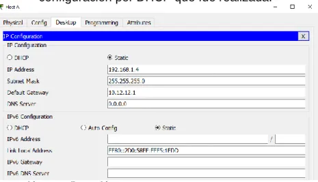
s. Obtener direcciones IPv4 en los host A, B, y D a través de la configuración por DHCP que fue realizada.
Ilustración 10 Configuración Host B
Ilustración 11 Configuración Host C
Part 2: conectividad de red de prueba y las opciones configuradas.
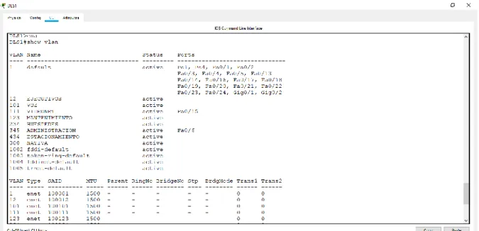
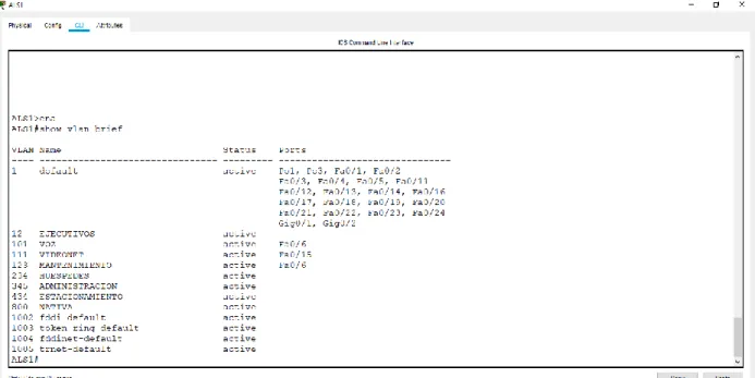
a. Verificar la existencia de las VLAN correctas en todos los switches y la asignación de puertos troncales y de acceso
Ilustración 13 Existencia de las VLAN en DLS1
Ilustración 15 Existencia de las VLAN en ALS1
Ilustración 16 Existencia de las VLAN en ALS2
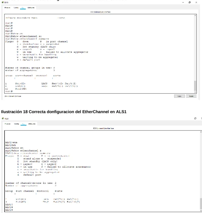
b. Verificar que el EtherChannel entre DLS1 y ALS1 está configurado correctamente
Comando
Ilustración 17 Correcta donfiguracion del EtherChannel en DLS1
c. Verificar la configuración de Spanning tree entre DLS1 o DLS2 para cada VLAN.
Ilustración 19 Configuración de Spanning tree en DLS1
d. Verificar la configuración de Spanning tree entre DLS1 o DLS2 para cada VLAN.
e. Verificar configuraciones HSRP mediante comandos Show Ilustración 21 Configuraciones HSRP
CONCLUSIONES
Con el desarrollo de la prueba de habilidades CCNP, se logra poner en práctica de un amanera amplia todos los temas vistos durante el desarrollo del diplomado de una manera dinámica por medio del desarrollo de dos escenarios basados en casos reales de diferentes empresas. En cada uno de los escenarios se desarrolló la configuración de acuerdo a las especificaciones dadas y finalmente se verifica la conectividad de red y control de la trayectoria.
En los dos escenarios se ejecutan funciones como el protocolo OSPF, EIGRP para IPv4 e IPv6, funciones LACP, PAgP, VTP versiones 2 y 3, Spanning tree root y ACL abarcando de esta manera todos los temas importantes y condicionando las configuraciones según las indicaciones dadas.
Los escenarios 1 y 2 de la prueba de habilidades CCNP se desarrolló usando el simulador Packet Tracer, en donde se aplicaron los conocimientos de
BIBLIOGRAFÍA
Froom, R., Frahim, E. (2015). CISCO Press (Ed). Spanning Tree Implementation. Implementing Cisco IP Switched Networks (SWITCH) Foundation
Learning Guide CCNP SWITCH 300-115. Recuperado de
https://1drv.ms/b/s!AmIJYei- NT1IlnWR0hoMxgBNv1CJ
Froom, R., Frahim, E. (2015). CISCO Press (Ed). InterVLAN Routing. Implementing Cisco IP Switched Networks (SWITCH) Foundation Learning
Guide CCNP SWITCH 300-115. Recuperado de
https://1drv.ms/b/s!AmIJYei-NT1IlnWR0hoMxgBNv1CJ
Froom, R., Frahim, E. (2015). CISCO Press (Ed). Fundamentals Review. Implementing Cisco IP Switched Networks (SWITCH) Foundation
Learning Guide CCNP SWITCH 300-115. Recuperado de
https://1drv.ms/b/s!AmIJYei- NT1IlnWR0hoMxgBNv1CJ
Gonzales, L. Protocolos de enrutamiento. Recuperado de:
http://www.ieslosviveros.es/alumnos/asig8/carpeta812/PROTOCOLOS_DE _ENRUTAMIENTO.pdf
Macfarlane, J. (2014). Network Routing Basics: Understanding IP Routing in Cisco Systems. Recuperado de:
https://web-a-ebscohost- com.bibliotecavirtual.unad.edu.co/ehost/detail/detail?vid=0&sid=65194da1-
a76e-44ed-9cd5-910fbcd0f4ab%40sessionmgr4006&bdata=Jmxhbmc9ZXMmc2l0ZT1laG9z dC1saXZl#AN=158227&db=e000xww
Macfarlane, J. (2014). Network Routing Basics: Understanding IP Routing in Cisco Systems. Recuperado de:
http://bibliotecavirtual.unad.edu.co:2048/login?url=http://search.ebscohost.c om/login.aspx?direct=true&db=e000xww&AN=158227&lang=es&site=ehost -live
Teare, D., Vachon B., Graziani, R. (2015). CISCO Press (Ed). Basic Network and Routing Concepts. Implementing Cisco IP Routing (ROUTE) Foundation
Learning Guide CCNP ROUTE 300-101. Recuperado de
https://1drv.ms/b/s!AmIJYei- NT1IlnMfy2rhPZHwEoWx
Teare, D., Vachon B., Graziani, R. (2015). CISCO Press (Ed). EIGRP Implementation. Implementing Cisco IP Routing (ROUTE) Foundation
Learning Guide CCNP ROUTE 300-101. Recuperado de
Teare, D., Vachon B., Graziani, R. (2015). CISCO Press (Ed). OSPF Implementation. Implementing Cisco IP Routing (ROUTE) Foundation
Learning Guide CCNP ROUTE 300-101. Recuperado de
https://1drv.ms/b/s!AmIJYei- NT1IlnMfy2rhPZHwEoWx
Teare, D., Vachon B., Graziani, R. (2015). CISCO Press (Ed). Manipulating Routing Updates. Implementing Cisco IP Routing (ROUTE) Foundation
Learning Guide CCNP ROUTE 300-101. Recuperado de