1
PRUEBA DE HABILIDADES PRACTICAS CCNA DIPLOMADO DE PROFUNDIZACION CISCO - DISEÑO E
IMPLEMENTACION DE SOLUCIONES INTEGRADAS LAN/WAN
PRESENTADO POR: DAVID BURBANO MARTÍNEZ
UNIVERSIDAD NACIONAL ABIERTA Y A DISTANCIA
ESCUELA DE CIENCIAS BÁSICAS, TECNOLOGÍA E INGENIERÍA PROGRAMA DE INGENIERÍA ELECTRÓNICA
2
PRUEBA DE HABILIDADES PRACTICAS CCNA DIPLOMADO DE PROFUNDIZACION CISCO - DISEÑO E
IMPLEMENTACION DE SOLUCIONES INTEGRADAS LAN/WAN
PRESENTADO POR: DAVID BURBANO MARTÍNEZ
TRABAJO DE GRADO PRESENTADO PARA OBTENER EL TÍTULO DE INGENIERO ELECTRÓNICO
Director
JUAN CARLOS VESGA
Tutor
DIEGO EDINSON RAMIREZ
UNIVERSIDAD NACIONAL ABIERTA Y A DISTANCIA
ESCUELA DE CIENCIAS BÁSICAS, TECNOLOGÍA E INGENIERÍA PROGRAMA DE INGENIERÍA ELECTRÓNICA
3
Nota de aceptación:
Firma del presidente del jurado
Firma del jurado
Firma del jurado
4 DEDICATORIA
5
AGRADECIMIENTOS
6 Tabla de contenido
Pag.
INTRODUCCIÓN ... 10
1 OBJETIVOS ... 11
1.1 Objetivo General ... 11
1.2 Objetivos Específicos... 11
2 SOLUCIÓN AL ESCENARIO 1 ... 12
2.1 Procedimientos de análisis y configuración en cada Router ... 13
2.1.1 Configuración direccionamiento IP ... 16
2.1.2 Configuración del enrutamiento establecido ... 19
2.1.3 Valores de Enrutamiento... 22
2.1.4 Suspender la expansion del protocolo RIP... 30
2.1.5 Observacion del protocolo RIP... 31
2.1.6 Analisi de cada router ... 35
2.1.7 Configuración de PPP y autenticación PAP y CHAP ... 39
2.1.8 Configuración de PAT ... 40
2.1.9 Configuración del servicio DHCP. ... 41
2.2 SOLUCIÓN AL ESCENARIO 2 ... 44
2.3 Configurar el direccionamiento IP ... 45
2. 3.1 Configuración PC de internet y Web server ... 46
2. 3.2 Configuración de router R1, R2 Y R3 ... 47
2. 3.3 Configuracion de switch 1, 2 Y 3 ... 49
2. 3.4 Tabla protocolo de enrutamiento ... 50
2. 3.5 Verificación de OSPF ... 52
2. 3.6 Configuración de seguridad ... 53
2. 3.7 Configuración vlan ... 56
2.3.8 direcciones IP a los switch ... 57
2.3.9 Desactivación de las interfaces ... 58
2.3.10 Implemente DHCP ... 59
2.3.11 COMANDO PING: ... 61
2.3.12 PING A LA VLAN ... 63
2.3.13 Verificación comando Tracert:... 66
3 CONCLUSIONES ... 68
7
LISTA DE TABLAS
pág.
Tabla 1. Router – interfaz……….…... 23
8
LISTA DE FIGURAS
pág.
Figura 1. Topología escenario 1 ... 12
Figura 2. Topología y conectividad ... 13
Figura 3. Enrutamiento ISP ... 22
Figura 4. Enrutamiento Medellin1 ... 22
Figura 5. Enrutamiento Medellin2 ... 23
Figura 6. Enrutamiento Medellin3 ... 23
Figura 7. Enrutamiento Bogota1 ... 24
Figura 8. Enrutamiento Bogota2 ... 24
Figura 9. Enrutamiento BOGOTA3 ... 25
Figura 10. Similtud de routers ... 25
Figura 11.Comparacion protocolos ... 25
Figura 12. Comparaciòn protocolos ... 26
Figura 13. Balanceo router ISP ... 27
Figura 14. Balanceo router MEDELLIN1 ... 27
Figura 15. Balanceo router MEDELLIN2 ... 27
Figura 16. Balanceo router MEDELLIN3 ... 28
Figura 17. Balanceo router BOGOTA1 ... 28
Figura 18. Balanceo router BOGOTA2... 28
Figura 19. Balanceo router BOGOTA3 ... 29
Figura 20. Rutas ISP... 29
Figura 21. Marcha de NAT en MEDELLN1 ... 40
Figura 22 . Marcha de NAT en BOGOTA1 ... 41
Figura 23. Configuración del servicio ... 41
Figura 24. Comprobación DHCP en PC-B ... 42
Figura 25. Topología escenario 2 ... 45
Figura 26. Topología packet Tracer ... 45
Figura 27. Configuración PC de internet ... 46
Figura 28. Configuración web server ... 46
Figura 29. Ping PC internet ... 62
Figura 30. Ping PC server ... 62
Figura 31. IP dinámica PC-A ... 64
9
Figura 33. Ping PC-A - PC-C ... 65
Figura 34. Acceso Web Server ... 65
Figura 35. PC-A al PC Internet ... 66
Figura 36. PC-A al Web Server ... 67
10
INTRODUCCIÓN
11
1 OBJETIVOS
1.1 Objetivo General
Comprender y aplicar los conocimientos prácticos o teóricos adquiridos en el curso de CCNA, con el desarrollo aplicativo para cada actividad practica propuesta en el entorno estableciendo una solución a cada escenario.
1.2 Objetivos Específicos
Configurar ACLs ROUTERS para establecer el protocolo OSPF y
dinámica de host. Verificar la funcionalidad de ACL.
Configurar la topología, direccionamiento IP, protocolos de
enrutamiento especificada en el escenario objeto de la prueba.
Realizar el direccionamiento IP de cada uno de los equipos que
conforman la red.
Establecer el diseño del esquema para cada componente práctico
12 2 Solución al escenario 1
Una empresa posee sucursales distribuidas en las ciudades de Bogotá y Medellín, en donde el estudiante será el administrador de la red, el cual deberá configurar e interconectar entre sí cada uno de los dispositivos que forman parte del escenario, acorde con los lineamientos establecidos para el direccionamiento IP, protocolos de enrutamiento y demás aspectos que forman parte de la topología de red.
Figura 1. Topologia escenario 1
13 Figura 2. Topología y conectividad
Solución escenario 1
2.1 Procedimientos de análisis y configuración en cada Router
Router ISP
Router>enable Router#config t
Enter configuration commands, one per line. End with CNTL/Z. Router(config)#hostname ISP
ISP(config)#no ip domain-lookup ISP(config)#line console 0
ISP(config-line)#password red ISP(config-line)#login
ISP(config-line)#line vty 0 15 ISP(config-line)#password red ISP(config-line)#login
14 Router MEDELLIN1
Router>enable Router#config t
Router(config)#hostname MEDELLIN1 MEDELLIN1(config)#no ip domain-lookup MEDELLIN1(config)#line console 0
MEDELLIN1(config-line)#password red MEDELLIN1(config-line)#login
MEDELLIN1(config-line)#line vty 0 15 MEDELLIN1(config-line)#password red MEDELLIN1(config-line)#login MEDELLIN1(config-line)#exit Router MEDELLIN2 Router>enable Router#config t Router(config)#hostname MEDELLIN2 MEDELLIN2(config)#no ip domain-lookup MEDELLIN2(config)#line console 0
MEDELLIN2(config-line)#password red MEDELLIN2(config-line)#login
MEDELLIN2(config-line)#line vty 0 15 MEDELLIN2(config-line)#password red MEDELLIN2(config-line)#login MEDELLIN2(config-line)#exit Router MEDELLIN3 Router>enable Router#config t Router(config)#hostname MEDELLIN3 MEDELLIN3(config)#no ip domain-lookup MEDELLIN3(config)#line console 0
MEDELLIN3(config-line)#password red MEDELLIN3(config-line)#login
MEDELLIN3(config-line)#line vty 0 15 MEDELLIN3(config-line)#password red MEDELLIN3(config-line)#login
MEDELLIN3(config-line)#exit
15 Router BOGOTA1
Router>enable Router#config t
Router(config)#hostname BOGOTA1 BOGOTA1(config)#no ip domain-lookup BOGOTA1(config)#line console 0
BOGOTA1(config-line)#password red BOGOTA1(config-line)#login
BOGOTA1(config-line)#line vty 0 15 BOGOTA1(config-line)#password red BOGOTA1(config-line)#login
BOGOTA1(config-line)#enable secret class Router BOGOTA2
Router>enable Router#config t
Router(config)#hostname BOGOTA2 BOGOTA2(config)#no ip domain-lookup BOGOTA2(config)#line console 0
BOGOTA2(config-line)#password red BOGOTA2(config-line)#login
BOGOTA2(config-line)#line vty 0 15 BOGOTA2(config-line)#password red BOGOTA2(config-line)#login
BOGOTA2(config-line)#enable secret class
Router BOGOTA3
Router>enable Router#config t
Router(config)#hostname BOGOTA3 BOGOTA3(config)#no ip domain-lookup BOGOTA3(config)#line console 0
BOGOTA3(config-line)#password red BOGOTA3(config-line)#login
BOGOTA3(config-line)#line vty 0 15 BOGOTA3(config-line)#password red BOGOTA3(config-line)#login
16 2.1.1 Configuración direccionamiento IP Configuración IP IPS
ISP(config)#int s0/0/0
ISP(config-if)#description conexion con MEDELLIN1 ISP(config-if)#ip address 209.17.220.1255.255.255.252
ISP(config-if)#clock rate 128000 ISP(config-if)#no shutdown ISP(config-if)#int s0/0/1
ISP(config-if)#description conexion con BOGOTA1 ISP(config-if)#ip address 209.17.220.5 255.255.255.252 ISP(config-if)#clock rate 128000
ISP(config-if)#no shutdown
Configuración IP MEDELLIN 1
MEDELLIN1(config)#int s0/0/0
MEDELLIN1(config-if)#description Conexion hacia MEDELLIN2 MEDELLIN1(config-if)#ip address 172.29.6.1 255.255.255.252 MEDELLIN1(config-if)#clock rate 128000
MEDELLIN1(config-if)#no shutdown MEDELLIN1(config-if)#int s0/0/1
MEDELLIN1(config-if)#description Conexion1 hacia MEDELLIN3 MEDELLIN1(config-if)#ip address 172.29.6.9 255.255.255.252 MEDELLIN1(config-if)#clock rate 128000
MEDELLIN1(config-if)#no shutdown MEDELLIN1(config-if)#int s0/1/0
MEDELLIN1(config-if)#description Conexion2 hacia MEDELLIN3 MEDELLIN1(config-if)#ip address 172.29.6.13 255.255.255.252 MEDELLIN1(config-if)#clock rate 128000
MEDELLIN1(config-if)#no shutdown MEDELLIN1(config-if)#int s0/1/1
MEDELLIN1(config-if)#description Conexion hacia ISP MEDELLIN1(config-if)#ip address 209.17.220.2 255.255.255.252
MEDELLIN1(config-if)#clock rate 128000 MEDELLIN1(config-if)#no shutdown
Configuración IP MEDELLIN 2
MEDELLIN2(config)#int s0/0/0
17 MEDELLIN2(config-if)#no shutdown
MEDELLIN2(config-if)#int s0/0/1
MEDELLIN2(config-if)#description Conexion con MEDELLIN3 MEDELLIN2(config-if)#ip address 172.29.6.5 255.255.255.252 MEDELLIN2(config-if)#clock rate 128000
MEDELLIN2(config-if)#no shutdown MEDELLIN2(config-if)#int f0/0
MEDELLIN2(config-if)#description Conexion con hosts
MEDELLIN2(config-if)#ip address 172.29.4.1 255.255.255.128 MEDELLIN2(config-if)#no shutdown
Configuración IP MEDELLIN3
MEDELLIN3(config)#int s0/0/0
MEDELLIN3(config-if)#description Conexion2 hacia MEDELLIN1 MEDELLIN3(config-if)#ip address 172.29.6.14 255.255.255.252 MEDELLIN3(config-if)#clock rate 128000
MEDELLIN3(config-if)#no shutdown MEDELLIN3(config-if)#int s0/0/1
MEDELLIN3(config-if)#description Conexion1 hacia MEDELLIN1 MEDELLIN3(config-if)#ip address 172.29.6.10 255.255.255.252 MEDELLIN3(config-if)#clock rate 128000
MEDELLIN3(config-if)#no shutdown MEDELLIN3(config-if)#int s0/1/0
MEDELLIN3(config-if)#description Conexion hacia MEDELLIN2 MEDELLIN3(config-if)#ip address 172.29.6.6 255.255.255.252 MEDELLIN3(config-if)#clock rate 128000
MEDELLIN3(config-if)#no shutdown MEDELLIN3(config-if)#int f0/0
MEDELLIN3(config-if)#description Conexion hacia hosts
MEDELLIN3(config-if)#ip address 172.29.4.129 255.255.255.128 MEDELLIN3(config-if)#no shutdown
Configuración IP BOGOTA1
BOGOTA1(config)#int s0/0/0
BOGOTA1(config-if)#description Conexion con ISP
BOGOTA1(config-if)#ip address 209.17.220.6 255.255.255.252 BOGOTA1(config-if)#clock rate 128000
BOGOTA1(config-if)#no shutdown BOGOTA1(config-if)#int s0/0/1
BOGOTA1(config-if)#description Conexion con BOGOTA2 BOGOTA1(config-if)#ip address 172.29.3.9 255.255.255.252 BOGOTA1(config-if)#clock rate 128000
18 BOGOTA1(config-if)#int s0/1/0
BOGOTA1(config-if)#description Conexion1 con BOGOTA2 BOGOTA1(config-if)#ip address 172.29.3.5 255.255.255.252 BOGOTA1(config-if)#clock rate 128000
BOGOTA1(config-if)#no shutdown BOGOTA1(config-if)#int s0/1/1
BOGOTA1(config-if)#description Conexion2 con BOGOTA2 BOGOTA1(config-if)#ip address 172.29.3.1 255.255.255.252 BOGOTA1(config-if)#clock rate 128000
BOGOTA1(config-if)#no shutdown
Configuración IP BOGOTA2
BOGOTA2(config)#int s0/0/0
BOGOTA2(config-if)#description Conexion con BOGOTA1 BOGOTA2(config-if)#ip address 172.29.3.10 255.255.255.252
BOGOTA2(config-if)#clock rate 128000 BOGOTA2(config-if)#no shutdown BOGOTA2(config-if)#int s0/0/1
BOGOTA2(config-if)#description Conexion con BOGOTA3 BOGOTA2(config-if)#ip address 172.29.3.13 255.255.255.252 BOGOTA2(config-if)#clock rate 128000
BOGOTA2(config-if)#no shutdown BOGOTA2(config-if)#int f0/0
BOGOTA2(config-if)#description Conexion con host
BOGOTA2(config-if)#ip address 172.29.1.1 255.255.255.0 BOGOTA2(config-if)#exit
BOGOTA2(config)#exit
Configuración IP BOGOTA3
BOGOTA3(config)#int s0/0/0
BOGOTA3(config-if)#description Conexion2 hacia BOGOTA1 BOGOTA3(config-if)#ip address 172.29.3.2 255.255.255.252 BOGOTA3(config-if)#clock rate 128000
BOGOTA3(config-if)#no shutdown BOGOTA3(config-if)#int s0/0/1
BOGOTA3(config-if)#description Conexion1 hacia BOGOTA1 BOGOTA3(config-if)#ip address 172.29.3.6 255.255.255.252 BOGOTA3(config-if)#clock rate 128000
19
BOGOTA3(config-if)#description Conexion hacia BOGOTA2 BOGOTA3(config-if)#ip address 172.29.3.14 255.255.255.252 BOGOTA3(config-if)#clock rate 128000
BOGOTA3(config-if)#no shutdown BOGOTA3(config-if)#int f0/0
BOGOTA3(config-if)#description Conexion hacia hosts BOGOTA3(config-if)#ip address 172.29.0.1 255.255.255.0 BOGOTA3(config-if)#no shutdown
2.1.2 Configuración del enrutamiento establecido
Enrutamiento en router ISP
Còdigo de configuraciòn de route rip ISP(config)#route rip
ISP(config-router)#version 2
ISP(config-router)#network 209.17.220.0 ISP(config-router)#network 209.17.220.4 ISP(config-router)#no auto-summary
Enrutamiento en router MEDELLIN1
Còdigo de configuraciòn de route rip
MEDELLIN1(config)#route rip
MEDELLIN1(config-router)#version 2
MEDELLIN1(config-router)#network 172.29.6.0 MEDELLIN1(config-router)#network 172.29.6.8 MEDELLIN1(config-router)#network 172.29.6.12 MEDELLIN1(config-router)#network 209.17.220.0 MEDELLIN1(config-router)#no auto-summary
Enrutamiento en router MEDELLIN2
Còdigo de configuraciòn de route rip
MEDELLIN2(config)#route rip
MEDELLIN2(config-router)#version 2
20
Enrutamiento en router MEDELLIN3 Còdigo de configuraciòn de route rip
MEDELLIN3(config)#route rip
MEDELLIN3(config-router)#version 2
MEDELLIN3(config-router)#network 172.29.6.4 MEDELLIN3(config-router)#network 172.29.6.8 MEDELLIN3(config-router)#network 172.29.6.12 MEDELLIN3(config-router)#no auto-summary
Enrutamiento en router BOGOTA1 Còdigo de configuraciòn de route rip
BOGOTA1(config)#route rip
BOGOTA1(config-router)#version 2
BOGOTA1(config-router)#network 209.17.220.6 BOGOTA1(config-router)#network 172.29.3.9 BOGOTA1(config-router)#network 172.29.3.5 BOGOTA1(config-router)#network 172.29.3.1 BOGOTA1(config-router)#no auto-summary
Enrutamiento en router BOGOTA2 Còdigo de configuraciòn de route rip
BOGOTA2(config)#route rip
BOGOTA2(config-router)#version 2
BOGOTA2(config-router)#network 172.29.3.8 BOGOTA2(config-router)#network 172.29.3.12 BOGOTA2(config-router)#no auto-summary
Enrutamiento en router BOGOTA3 Còdigo de configuraciòn de route rip
BOGOTA3(config)#route rip
BOGOTA3(config-router)#version 2
21
Los routers Bogota1 y Medellín deberán añadir a su configuración de
enrutamiento una ruta por defecto hacia el ISP y, a su vez, redistribuirla dentro de las publicaciones de RIP.
MEDELLIN1(config)#ip route 0.0.0.0 0.0.0.0 s0/1/1 Redistribuciòn dentro de las publicaciones de RIP MEDELLIN1(config)#route rip
MEDELLIN1(config-router)#version 2
MEDELLIN1(config-router)#default-information originate
BOGOTA1(config)#ip route 0.0.0.0 0.0.0.0 s0/0/0 Redistribuciòn dentro de las publicaciones de RIP
BOGOTA1(config)#route rip
BOGOTA1(config-router)#version 2
BOGOTA1(config-router)# default-information originate
El router ISP deberá tener una ruta estática dirigida hacia cada red interna de
Bogotá y Medellín para el caso se sumarizan las subredes de cada uno a /22.
Se calcula la sumarización de cada red: La red Medellìn con dirección ip 172.29.4.0 La red Bogotà con dirección ip 172.29.0.0
Ruta estàtica dirigida hacia la red inrterna de MEDELLIN
ISP(config)#ip route 172.29.4.0 255.255.252.0 s0/0/0
Ruta estàtica dirigida hacia la red inrterna de BOGOTA
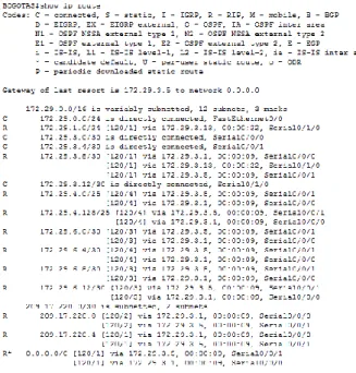
22 2.1.3 Valores de Enrutamiento
Verificar la tabla de enrutamiento en cada uno de los routers para
comprobar las redes y sus rutas.
Figura 3. Enrutamiento ISP
Figura 4. Enrutamiento MEDELLIN1
23
Figura 5. Enrutamiento MEDELLIN2
24
Figura 7. Enrutamiento BOGOTA1
25
Figura 9. Enrutamiento BOGOTA3
Obsérvese en los routers Bogotá1 y Medellín1 cierta similitud por su ubicación,
por tener dos enlaces de conexión hacia otro router y por la ruta por defecto que manejan.
Figura 10. Similtud de routers
26
Los routers Medellín2 y Bogotá2 también presentan redes conectadas
directamente y recibidas mediante RIP
Figura 12. Comparaciòn protocolos
Las tablas de los routers restantes deben permitir visualizar rutas redundantes para el caso de la ruta por defecto.
Verificar el balanceo de carga que muestran los routers.
Este balanceo de carga se observa encada dato establecidos datos
señalados proporcionado balance en cada router.
Las rutas redundantes indican màs de un camino para acceder a la ip
27
Figura 13. Balanceo router ISP
Figura 14. Balanceo router MEDELLIN1
28
Figura 16. Balanceo router MEDELLIN3
Figura 17. Balanceo router BOGOTA1
29
Figura 19. Balanceo router BOGOTA3
El router ISP solo debe indicar sus rutas estáticas adicionales a las
directamente conectadas.
30 2.1.4 Suspender la expansión del protocolo RIP
Para no propagar las publicaciones por interfaces que no lo requieran se debe deshabilitar la propagación del protocolo RIP, en la siguiente tabla se indican las interfaces de cada router que no necesitan desactivación.
ROUTER INTERFAZ
Bogota1 SERIAL0/0/1; SERIAL0/1/0; SERIAL0/1/1
Bogota2 SERIAL0/0/0;
SERIAL0/0/1 Bogota3 SERIAL0/0/0; SERIAL0/0/1;
SERIAL0/1/0
Medellín1 SERIAL0/0/0; SERIAL0/0/1; SERIAL0/1/1
Medellín2 SERIAL0/0/0; SERIAL0/0/1 Medellín3 SERIAL0/0/0; SERIAL0/0/1; SERIAL0/1/0
ISP No requiere
Tabla 1. Router - Interfaz ISP(config)#route rip
ISP(config-router)#passive-interface f0/0 ISP(config-router)#passive-interface f0/1 MEDELLIN1(config)#route rip
MEDELLIN1(config-router)#passive-interface f0/0 MEDELLIN1(config-router)#passive-interface f0/1 MEDELLIN1(config-router)#passive-interface s0/1/1 MEDELLIN2(config)#route rip
31 MEDELLIN3(config-router)#passive-interface f0/0 MEDELLIN3(config-router)#passive-interface f0/1 BOGOTA1(config)#route rip
BOGOTA1(config-router)#passive-interface f0/0 BOGOTA1(config-router)#passive-interface f0/1 BOGOTA1 (config-router)#passive-interface s0/0/0 BOGOTA2(config)#route rip
BOGOTA2(config-router)#passive-interface f0/0 BOGOTA2(config-router)#passive-interface f0/1 BOGOTA3(config)#route rip
BOGOTA3(config-router)#passive-interface f0/0 BOGOTA3(config-router)#passive-interface f0/1
2.1.5 Observación del protocolo RIP
Verificar y documentar las opciones de enrutamiento configuradas en los routers,
como el passive interface para la conexión hacia el ISP, la versión de RIP y las interfaces que participan de la publicación entre otros datos.
Verificación de cada protocolo RIP
MEDELLIN2#sh ip protocol Routing Protocol is "rip"
Sending updates every 30 seconds, next due in 15 seconds Invalid after 180 seconds, hold down 180, flushed after 240 Outgoing update filter list for all interfaces is not set Incoming update filter list for all interfaces is not set Redistributing: rip
Default version control: send version 2, receive 2 Interface Send Recv Triggered RIP Key-chain Serial0/0/1 2 2
Serial0/0/0 2 2
Automatic network summarization is not in effect Maximum path: 4
Routing for Networks: 172.29.0.0
192.29.6.0
32
Routing Information Sources:
Gateway Distance Last Update 172.29.6.2 120 00:00:11
172.29.6.6 120 00:00:07 Distance: (default is 120)
MEDELLIN3#sh ip protocol Routing Protocol is "rip"
Sending updates every 30 seconds, next due in 21 seconds Invalid after 180 seconds, hold down 180, flushed after 240 Outgoing update filter list for all interfaces is not set Incoming update filter list for all interfaces is not set Redistributing: rip
Default version control: send version 2, receive 2 Interface Send Recv Triggered RIP Key-chain GigabitEthernet0/1 2 2 Serial0/0/1 2 2
Serial0/0/0 2 2
Automatic network summarization is not in effect Maximum path: 4
Routing for Networks:
172.29.0.0 192.29.3.0 192.29.6.0 192.168.6.0 Passive Interface(s): GigabitEthernet0/0
Routing Information Sources:
Gateway Distance Last Update
172.29.6.14 120 00:00:09 172.29.6.5 120 00:00:08 Distance: (default is 120)
MEDELLIN1#sh ip protocol Routing Protocol is "rip"
Sending updates every 30 seconds, next due in 25 seconds Invalid after 180 seconds, hold down 180, flushed after 240 Outgoing update filter list for all interfaces is not set Incoming update filter list for all interfaces is not set Redistributing: rip
Default version control: send version 2, receive 2 Interface Send Recv Triggered RIP Key-chain Serial0/1/0 2 2
Serial0/0/0 2 2 Serial0/0/1 2 2
33
path: 4
Routing for Networks: 172.29.0.0
192.168.6.0 209.17.220.0
Passive Interface(s): GigabitEthernet0/1
Routing Information Sources:
Gateway Distance Last Update
209.17.220.2 120 00:00:00 172.29.6.1 120 00:00:25 172.29.6.9 120 00:00:21 172.29.6.13 120 00:00:21
Distance: (default is 120) ISP#sho ip route protocol
Translating "protocol"...domain server (255.255.255.255) % Invalid input detected ISP#sho ip
protocol Routing Protocol is "rip"
Sending updates every 30 seconds, next due in 25 seconds Invalid after 180 seconds, hold down 180, flushed after 240 Outgoing update filter list for all interfaces is not set
Incoming update filter list for all interfaces is not set Redistributing: rip
Default version control: send version 2, receive 2 Interface Send Recv Triggered RIP Key-chain Serial0/0/1 2 2
Serial0/0/0 2 2
Automatic network summarization is not in effect Maximum path: 4
Routing for Networks: 209.17.220.0
Passive Interface(s):
Routing Information Sources:
Gateway Distance Last Update 209.17.220.6 120 00:00:13
209.17.220.1 120 00:00:01 Distance: (default is 120)
BOGOTA1#sh ip protocol Routing Protocol is "rip"
34
list for all interfaces is not set Incoming update filter list for all interfaces is not set Redistributing: rip
Default version control: send version 2, receive 2 Interface Send Recv Triggered RIP Key-chain Serial0/0/1 2 2
Serial0/1/0 2 2 Serial0/0/0 2 2
Automatic network summarization is not in effect Maximum path: 4
Routing for Networks: 172.29.0.0 192.29.3.0
209.17.220.0 209.168.220.0
Passive Interface(s):
GigabitEthernet0/0
Routing Information Sources: Gateway Distance Last Update 172.29.3.2 120 00:00:12
172.29.3.6 120 00:00:12 172.29.3.10 120 00:00:20 209.17.220.5 120 00:00:20 Distance: (default is 120)
BOGOTA2#sh ip protocol Routing Protocol is "rip"
Sending updates every 30 seconds, next due in 19 seconds Invalid after 180 seconds, hold down 180, flushed after 240 Outgoing update filter list for all interfaces is not set Incoming update filter list for all interfaces is not set Redistributing: rip
Default version control: send version 2, receive 2 Interface Send Recv Triggered RIP Key-chain Serial0/0/1 2 2
Serial0/0/0 2 2
Automatic network summarization is not in effect Maximum path: 4
Routing for Networks: 172.29.0.0
192.29.3.0
Passive Interface(s): GigabitEthernet0/0
Routing Information Sources:
Gateway Distance Last Update
35
BOGOTA3#sh ip protocol Routing Protocol is "rip"
Sending updates every 30 seconds, next due in 10 seconds Invalid after 180 seconds, hold down 180, flushed after 240 Outgoing update filter list for all interfaces is not set Incoming update filter list for all interfaces is not set Redistributing: rip
Default version control: send version 2, receive 2 Interface Send Recv Triggered RIP Key-chain GigabitEthernet0/1 2 2 Serial0/0/1 2 2
Serial0/0/0 2 2
Automatic network summarization is not in effect Maximum path: 4
Routing for Networks: 172.29.0.0 Passive Interface(s):
GigabitEthernet0/0
Routing Information Sources: Gateway Distance Last Update 172.29.3.13 120 00:00:00
172.29.3.5 120 00:00:14 Distance: (default is 120)
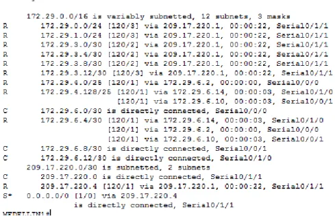
Verificar y documentar la base de datos de RIP de cada router, donde se informa de manera
detallada de todas las rutas hacia cada red.
2.1.6 Analisis de cada router
ISP
172.29.0.0/16 is variably subnetted, 12 subnets, 3 masks
R 172.29.0.0/24 [120/2] via 209.17.220.6, 00:00:10, Serial0/0/1 R
172.29.1.0/24 [120/2] via 209.17.220.6, 00:00:10, Serial0/0/1 R
172.29.3.0/30 [120/1] via 209.17.220.6, 00:00:10, Serial0/0/1 R
172.29.3.4/30 [120/1] via 209.17.220.6, 00:00:10, Serial0/0/1 R
172.29.3.8/30 [120/1] via 209.17.220.6, 00:00:10, Serial0/0/1 R
172.29.3.12/30 [120/2] via 209.17.220.6, 00:00:10, Serial0/0/1 R
172.29.4.0/25 [120/2] via 209.17.220.1, 00:00:16, Serial0/0/0
R 172.29.4.128/25 [120/2] via 209.17.220.1, 00:00:16, Serial0/0/0 R 172.29.6.0/30 [120/1] via 209.17.220.1, 00:00:16, Serial0/0/0
R 172.29.6.4/30 [120/2] via 209.17.220.1, 00:00:16, Serial0/0/0 R
172.29.6.8/30 [120/1] via 209.17.220.1, 00:00:16, Serial0/0/0 R
172.29.6.12/30 [120/1] via 209.17.220.1, 00:00:16, Serial0/0/0
36
L 209.17.220.2/32 is directly connected, Serial0/0/0 C
209.17.220.4/30 is directly connected, Serial0/0/1 L
209.17.220.5/32 is directly connected, Serial0/0/1
Medellin1
172.29.0.0/16 is variably subnetted, 13 subnets, 4 masks
R 172.29.0.0/24 [120/3] via 209.17.220.2, 00:00:10, Serial0/1/0 R
172.29.1.0/24 [120/3] via 209.17.220.2, 00:00:10, Serial0/1/0 R
172.29.3.0/30 [120/2] via 209.17.220.2, 00:00:10, Serial0/1/0 R
172.29.3.4/30 [120/2] via 209.17.220.2, 00:00:10, Serial0/1/0 R
172.29.3.8/30 [120/2] via 209.17.220.2, 00:00:10, Serial0/1/0 R
172.29.3.12/30 [120/3] via 209.17.220.2, 00:00:10, Serial0/1/0 R
172.29.4.0/25 [120/1] via 172.29.6.1, 00:00:07, Serial0/0/1 R 172.29.4.128/25 [120/1] via 172.29.6.13, 00:00:15, Serial0/0/0 C 172.29.6.0/30 is directly connected, Serial0/0/1 L 172.29.6.2/32 is directly connected, Serial0/0/1
R 172.29.6.4/30 [120/1] via 172.29.6.1, 00:00:07, Serial0/0/1 [120/1] via 172.29.6.13, 00:00:15, Serial0/0/0
C 172.29.6.12/30 is directly connected, Serial0/0/0 L 172.29.6.14/32 is directly connected, Serial0/0/0
209.17.220.0/24 is variably subnetted, 3 subnets, 2 masks C 209.17.220.0/30 is directly connected, Serial0/1/0
L 209.17.220.1/32 is directly connected, Serial0/1/0
R 209.17.220.4/30 [120/1] via 209.17.220.2, 00:00:10, Serial0/1/0
Medellin2
172.29.0.0/16 is variably subnetted, 15 subnets, 4 masks
R 172.29.0.0/24 [120/4] via 172.29.6.2, 00:00:21, Serial0/0/1 R
172.29.1.0/24 [120/4] via 172.29.6.2, 00:00:21, Serial0/0/1 R
172.29.3.0/30 [120/3] via 172.29.6.2, 00:00:21, Serial0/0/1 R
172.29.3.4/30 [120/3] via 172.29.6.2, 00:00:21, Serial0/0/1 R
172.29.3.8/30 [120/3] via 172.29.6.2, 00:00:21, Serial0/0/1 R
172.29.3.12/30 [120/4] via 172.29.6.2, 00:00:21, Serial0/0/1
C 172.29.4.0/25 is directly connected, GigabitEthernet0/0 L 172.29.4.1/32 is directly connected, GigabitEthernet0/0
R 172.29.4.128/25 [120/1] via 172.29.6.6, 00:00:12, Serial0/0/0 C 172.29.6.0/30 is directly connected, Serial0/0/1 L
172.29.6.1/32 is directly connected, Serial0/0/1 C
172.29.6.4/30 is directly connected, Serial0/0/0 L
172.29.6.5/32 is directly connected, Serial0/0/0
R 172.29.6.8/30 [120/1] via 172.29.6.6, 00:00:12, Serial0/0/0 [120/1] via 172.29.6.2, 00:00:21, Serial0/0/1
37 172.29.6.2, 00:00:21, Serial0/0/1
209.17.220.0/30 is subnetted, 2 subnets
R 209.17.220.0/30 [120/1] via 172.29.6.2, 00:00:21, Serial0/0/1 R 209.17.220.4/30 [120/2] via 172.29.6.2, 00:00:21, Serial0/0/1
Medellin3
172.29.0.0/16 is variably subnetted, 14 subnets, 4 masks
R 172.29.0.0/24 [120/4] via 172.29.6.14, 00:00:15, Serial0/0/1 R 172.29.1.0/24 [120/4] via 172.29.6.14, 00:00:15, Serial0/0/1 R 172.29.3.0/30 [120/3] via 172.29.6.14, 00:00:15, Serial0/0/1 R 172.29.3.4/30 [120/3] via 172.29.6.14, 00:00:15, Serial0/0/1 R 172.29.3.8/30 [120/3] via 172.29.6.14, 00:00:15, Serial0/0/1 R 172.29.3.12/30 [120/4] via 172.29.6.14, 00:00:15, Serial0/0/1 R 172.29.4.0/25 [120/1] via 172.29.6.5, 00:00:23, Serial0/0/0 C 172.29.4.128/25 is directly connected, GigabitEthernet0/0 L 172.29.4.129/32 is directly connected, GigabitEthernet0/0 R
172.29.6.0/30 [120/1] via 172.29.6.5, 00:00:23, Serial0/0/0 [120/1] via 172.29.6.14, 00:00:15, Serial0/0/1
C 172.29.6.4/30 is directly connected, Serial0/0/0 L 172.29.6.6/32 is directly connected, Serial0/0/0 C 172.29.6.12/30 is directly connected, Serial0/0/1 L 172.29.6.13/32 is directly connected, Serial0/0/1 209.17.220.0/30 is subnetted, 2 subnets
R 209.17.220.0/30 [120/1] via 172.29.6.14, 00:00:15, Serial0/0/1 R 209.17.220.4/30 [120/2] via 172.29.6.14, 00:00:15, Serial0/0/1
Bogota1
172.29.0.0/16 is variably subnetted, 13 subnets, 4 masks
R 172.29.0.0/24 [120/1] via 172.29.3.6, 00:00:16, Serial0/1/0 C 172.29.3.4/30 is directly connected, Serial0/1/0 L
172.29.3.5/32 is directly connected, Serial0/1/0 C
172.29.3.8/30 is directly connected, Serial0/0/1 L
172.29.3.9/32 is directly connected, Serial0/0/1
R 172.29.3.12/30 [120/1] via 172.29.3.6, 00:00:16, Serial0/1/0 [120/1] via 172.29.3.10, 00:00:07, Serial0/0/1
R 172.29.4.0/25 [120/3] via 209.17.220.5, 00:00:14, Serial0/0/0
R 172.29.4.128/25 [120/3] via 209.17.220.5, 00:00:14, Serial0/0/0 R 172.29.6.0/30 [120/2] via 209.17.220.5, 00:00:14, Serial0/0/0
R 172.29.6.4/30 [120/3] via 209.17.220.5, 00:00:14, Serial0/0/0 R
38
172.29.6.12/30 [120/2] via 209.17.220.5, 00:00:14, Serial0/0/0 209.17.220.0/24 is variably subnetted, 3 subnets, 2 masks
R 209.17.220.0/30 [120/1] via 209.17.220.5, 00:00:14, Serial0/0/0 C 209.17.220.4/30 is directly connected, Serial0/0/0 L 209.17.220.6/32 is directly connected, Serial0/0/0
Bogota2
172.29.0.0/16 is variably subnetted, 15 subnets, 4 masks R 172.29.0.0/24 [120/1] via 172.29.3.14, 00:00:01, Serial0/0/1
C 172.29.1.0/24 is directly connected, GigabitEthernet0/0 L 172.29.1.1/32 is directly connected, GigabitEthernet0/0
R 172.29.3.0/30 [120/1] via 172.29.3.9, 00:00:11, Serial0/0/0 [120/1] via 172.29.3.14, 00:00:01, Serial0/0/1
R 172.29.3.4/30 [120/1] via 172.29.3.9, 00:00:11, Serial0/0/0 [120/1] via 172.29.3.14, 00:00:01, Serial0/0/1
C 172.29.3.8/30 is directly connected, Serial0/0/0 L
172.29.3.10/32 is directly connected, Serial0/0/0 C
172.29.3.12/30 is directly connected, Serial0/0/1 L
172.29.3.13/32 is directly connected, Serial0/0/1
R 172.29.4.0/25 [120/4] via 172.29.3.9, 00:00:11, Serial0/0/0
R 172.29.4.128/25 [120/4] via 172.29.3.9, 00:00:11, Serial0/0/0 R 172.29.6.0/30 [120/3] via 172.29.3.9, 00:00:11, Serial0/0/0
R 172.29.6.4/30 [120/4] via 172.29.3.9, 00:00:11, Serial0/0/0 R
172.29.6.8/30 [120/3] via 172.29.3.9, 00:00:11, Serial0/0/0 R
172.29.6.12/30 [120/3] via 172.29.3.9, 00:00:11, Serial0/0/0 209.17.220.0/30 is subnetted, 2 subnets
R 209.17.220.0/30 [120/2] via 172.29.3.9, 00:00:11, Serial0/0/0 R 209.17.220.4/30 [120/1] via 172.29.3.9, 00:00:11, Serial0/0/0
Bogota3
172.29.0.0/16 is variably subnetted, 14 subnets, 4 masks C
172.29.0.0/24 is directly connected, GigabitEthernet0/0 L
172.29.0.1/32 is directly connected, GigabitEthernet0/0
R 172.29.1.0/24 [120/1] via 172.29.3.13, 00:00:10, Serial0/0/1 C 172.29.3.4/30 is directly connected, Serial0/0/0 L 172.29.3.6/32 is directly connected, Serial0/0/0
R 172.29.3.8/30 [120/1] via 172.29.3.5, 00:00:27, Serial0/0/0 [120/1] via 172.29.3.13, 00:00:10, Serial0/0/1
39 172.29.3.14/32 is directly connected, Serial0/0/1
R 172.29.4.0/25 [120/4] via 172.29.3.5, 00:00:27, Serial0/0/0
R 172.29.4.128/25 [120/4] via 172.29.3.5, 00:00:27, Serial0/0/0 R 172.29.6.0/30 [120/3] via 172.29.3.5, 00:00:27, Serial0/0/0
R 172.29.6.4/30 [120/4] via 172.29.3.5, 00:00:27, Serial0/0/0 R
172.29.6.8/30 [120/3] via 172.29.3.5, 00:00:27, Serial0/0/0 R
172.29.6.12/30 [120/3] via 172.29.3.5, 00:00:27, Serial0/0/0
209.17.220.0 /30 is subnetted, 2 subnets
R 209.17.220.0/30 [120/2] via 172.29.3.5, 00:00:27, Serial0/0/0 R 209.17.220.4/30 [120/1] via 172.29.3.5, 00:00:27, Serial0/0/0
2.1.7 Configuración de PPP y autenticación PAP y CHAP
Medellín1 con ISP se configura con autenticación PAP.
MEDELLIN1(config)#username USER password unadavid MEDELLIN1(config)#int s0/1/1
MEDELLIN1(config-if)#encapsulation ppp MEDELLIN1(config-if)#ppp authentication pap
MEDELLIN1(config-if)#ppp pap sent-username USER password unadavid ISP(config)#username USER password unadavid
ISP(config)#int s0/0/0
ISP(config-if)#encapsulation ppp ISP(config-if)#ppp authentication pap
ISP(config-if)#ppp pap sent-username USER password unadavid
Bogotá1 con ISP se configura con autenticación CHAP.
BOGOTA1(config)#username ISP password unadavid BOGOTA1(config)#int s0/0/0
BOGOTA1(config-if)#encapsulation ppp BOGOTA1(config-if)#ppp authentication chap
40 ISP(config)#int s0/0/1
ISP(config-if)#encapsulation ppp ISP(config-if)#ppp authentication chap
2.1.8 Configuración de PAT
se activa NAT en cada salida como es Bogotá1 y Medellín1, los routers
internos de un lugar no llegan hasta los routers internos en el otro lado, la comunicación se daria hasta los routers Bogotá1, ISP y Medellín1.
Configuración de NAT en el router Medellín1.
MEDELLIN1(config)#access-list 1 permit 172.29.4.0 0.0.3.255
MEDELLIN1(config)#ip nat inside source list 1 interface Serial0/1/1 overload MEDELLIN1(config)#interface S0/1/1
MEDELLIN1(config-if)#ip nat outside MEDELLIN1(config-if)#interface S0/0/0 MEDELLIN1(config-if)#ip nat inside MEDELLIN1(config-if)#interface S0/0/1 MEDELLIN1(config-if)#ip nat inside MEDELLIN1(config-if)#interface S0/1/0 MEDELLIN1(config-if)#ip nat inside
Compruebe que la traducción de direcciones indique las interfaces de entrada
y de salida. Al realizar una prueba de ping, la dirección debe ser traducida automáticamente a la dirección de la interfaz serial 0/1/0 del router Medellín1, cómo diferente puerto.
PAT usa un puerto cada vez que hace una conexión y este va cambiando
41
Proceda a configurar el NAT en el router Bogotá1.
BOGOTA1 (config)#access-list 1 permit 172.29.0.0 0.0.3.255
BOGOTA1(config)#ip nat inside source list 1 interface s0/0/0 overload BOGOTA1(config)#int s0/0/0
BOGOTA1(config-if)#ip nat outside BOGOTA1(config-if)#int s0/0/1 BOGOTA1(config-if)#ip nat inside BOGOTA1(config-if)#int s0/1/0 BOGOTA1(config-if)#ip nat inside BOGOTA1(config-if)#int s0/1/1 BOGOTA1(config-if)#ip nat inside
Compruebe que la traducción de direcciones indique las interfaces de entrada
y de salida. Al realizar una prueba de ping, la dirección debe ser traducida automáticamente a la dirección de la interfaz serial 0/1/0 del router Bogotá1, cómo diferente puerto.
Figura 22 . Marcha de NAT en BOGOTA1
2.1.9 Configuración del servicio DHCP.
Figura 23. Configuración del servicio
Configurar la red Medellín2 y Medellín3 donde el router Medellín 2 debe ser el
42
MEDELLIN2 (config)#ip dhcp excluded-address 172.29.4.0 172.29.4.6 MEDELLIN2 (config)#ip dhcp excluded-address 172.29.4.128 172.29.4.133 MEDELLIN2(config)# ip dhcp pool MEDELLIN3
MEDELLIN2(dhcp-config)#network 172.29.4.128 255.255.255.128 MEDELLIN2(dhcp-config)#default-router 172.29.4.129
MEDELLIN2(dhcp-config)#dns-server 1.1.1.1 MEDELLIN2(config)# ip dhcp pool MEDELLIN2
MEDELLIN2(dhcp-config)#network 172.29.4.0 255.255.255.128 MEDELLIN2(dhcp-config)#default-router 172.29.4.1
MEDELLIN2(dhcp-config)#dns-server 1.1.1.1
El router Medellín3 deberá habilitar el paso de los mensajes broadcast
hacia la IP del router Medellín2.
43
Configurar la red Bogotá2 y Bogotá3 donde el router Medellín2 debe ser el
servidor DHCP para ambas redes Lan.
BOGOTA2(config)#ip dhcp excluded-address 172.29.1.1 172.29.1.6
BOGOTA2(config)#ip dhcp excluded-address 172.29.0.1 172.29.0.6 BOGOTA2(config)# ip dhcp pool BOGOTA3
BOGOTA2(dhcp-config)#network 172.29.0.0 255.255.255.0
BOGOTA2(dhcp-config)#default-router 172.29.0.1
BOGOTA2(dhcp-config)#dns-server 1.1.1.1
BOGOTA2(config)# ip dhcp pool BOGOTA2
BOGOTA2(dhcp-config)#network 172.29.1.0
255.255.255.0
BOGOTA2(dhcp-config)#default-router 172.29.1.1
BOGOTA2(dhcp-config)#dns-server 1.1.1.1
Configure el router Bogotá1 para que habilite el paso de los mensajes
Broadcast hacia la IP del router Bogotá2.
BOGOTA3(config)#int f0/0
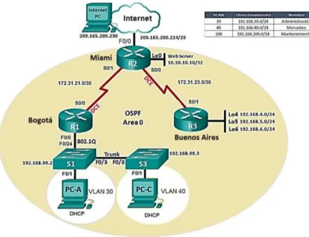
44 2.2 Solución al escenario 2
Una empresa de Tecnología posee tres sucursales distribuidas en las ciudades de Miami, Bogotá y Buenos Aires, en donde el estudiante será el administrador de la red, el cual deberá configurar e interconectar entre sí cada uno de los dispositivos que forman parte del escenario, acorde con los lineamientos establecidos para el direccionamiento IP, protocolos de enrutamiento y demás aspectos que forman parte de la topología de red.
Topología de red
45 2.3 Configurar el direccionamiento IP
Acorde con la topología de red para cada uno de los dispositivos que forman parte del escenario:
En este escenario se realiza la siguiente conexión utilizando cada router y dando solución al problema planteado.
Se identifica los siguientes puertos de conexión R1-S1-S3-PC-A-PC-C y la
configuración puertos de enlace serial routers.
46
2. 3.1 Configuración PC de internet y Web server
Figura 27. Configuración PC de internet
47
Conexión de puertos fast Ethernet PC internet y Web server
Puertos conexión R1-S1-S3-PC-A-PC-
Configuración puertos enlace serial routers
2. 3.2 Configuración de router R1, R2 Y R3
Configuración Router R1:
Router>en Router#conf t
Enter configuration commands, one per line. End with CNTL/Z. Router(config)#host R1
R1(config)#int s2/0
R1(config-if)#description connection to R2
R1(config-if)#ip add 172.31.21.1 255.255.255.252 R1(config-if)#clock rate 256000
R1(config-if)#no shut
%LINK-5-CHANGED: Interface Serial2/0, changed state to down R1(config-if)#exit
R1(config)#ip route 0.0.0.0 0.0.0.0 s2/0
Configuración Router R2
Router>en Router#conf t
Enter configuration commands, one per line. End with CNTL/Z. Router(config)#host R2
R2(config)#int s3/0
R2(config-if)#descrip connection to R1
R2(config-if)#ip add 172.31.21.2 255.255.255.252 R2(config-if)#no shut
R2(config-if)#
%LINK-5-CHANGED: Interface Serial3/0, changed state to up
%LINEPROTO-5-UPDOWN: Line protocol on Interface Serial3/0, changed state to up
R2(config-if)#int s2/0
48
R2(config-if)#ip add 172.31.23.1 255.255.255.252 R2(config-if)#clock rate 256000
R2(config-if)#no shut
%LINK-5-CHANGED: Interface Serial2/0, changed state to down R2(config-if)#
R2(config-if)#int f0/0
R2(config-if)#descrip internet
R2(config-if)#ip add 209.165.200.225 255.255.255.248 R2(config-if)#no shut
R2(config-if)#
%LINK-5-CHANGED: Interface FastEthernet0/0, changed state to up R2(config-if)#int f1/0
R2(config-if)#ip add 10.10.10.1 255.255.255.0 R2(config-if)#no shut
R2(config-if)#
%LINK-5-CHANGED: Interface FastEthernet1/0, changed state to up R2(config-if)#description connection to web server
R2(config-if)#exit
R2(config)#ip route 0.0.0.0 0.0.0.0 f0/0 R2(config)#
Configuración Router R3
Router>en Router#conf t
Enter configuration commands, one per line. End with CNTL/Z. Router(config)#host R3
R3(config)#int s3/0
R3(config-if)#description connection to R2
R3(config-if)#ip add 172.31.23.2 255.255.252.252 Bad mask 0xFFFFFCFC for address 172.31.23.2 R3(config-if)#ip add 172.31.23.2 255.255.255.252 R3(config-if)#no shut
R3(config-if)#int lo4 R3(config-if)#
%LINK-5-CHANGED: Interface Loopback4, changed state to up
%LINEPROTO-5-UPDOWN: Line protocol on Interface Loopback4, changed state to up
R3(config-if)#ip add 192.168.4.1 255.255.255.0 R3(config-if)#no shut
R3(config-if)#int lo5 R3(config-if)#
49
%LINEPROTO-5-UPDOWN: Line protocol on Interface Loopback5, changed state to up
R3(config-if)#ip add 192.168.5.1 255.255.255.0 R3(config-if)#no shut
R3(config-if)#int lo6 R3(config-if)#
%LINK-5-CHANGED: Interface Loopback6, changed state to up
%LINEPROTO-5-UPDOWN: Line protocol on Interface Loopback6, changed state to up
R3(config-if)#ip add 192.168.6.1 255.255.255.0 R3(config-if)#exit
R3(config)#ip route 0.0.0.0 0.0.0.0 s3/0 R3(config)#
R3#
%SYS-5-CONFIG_I: Configured from console by console
2. 3.3 Configuracion de switch 1, 2 Y 3 Configuración Switch 1
Switch>en Switch#conf t
Enter configuration commands, one per line. End with CNTL/Z. Switch(config)#no ip domain-loo
Switch(config)#no ip domain-lookup Switch(config)#host S1
S1(config)# S1#
%SYS-5-CONFIG_I: Configured from console by console
Configuración Switch 3
Switch>en Switch#conf t
Enter configuration commands, one per line. End with CNTL/Z. Switch(config)#no ip domain-loo
Switch(config)#no ip domain-lookup Switch(config)#host S3
S3(config)# S1#
50 2. 3.4 Tabla protocolo de enrutamiento
Configurar el protocolo de enrutamiento OSPFv2 bajo los siguientes criterios:
Tabla 2.configuracion protocolo de enrutamiento
Configuración en R1:
R1>en Password: R1#conf t
Enter configuration commands, one per line. End with CNTL/Z. R1(config)#router ospf 1
R1(config-router)#router-id 1.1.1.1
R1(config-router)#network 172.31.21.0 0.0.0.3 area 0 R1(config-router)#network 192.168.30.0 0.0.0.255 area 0 R1(config-router)#network 192.168.40.0 0.0.0.255 area 0 R1(config-router)#network 192.168.200.0 0.0.0.255 area 0 R1(config-router)#passive-interface f0/0.30
R1(config-router)#passive-interface f0/0.40 R1(config-router)#passive-interface f0/0.200 R1(config-router)#exit
R1(config)#
%LINK-5-CHANGED: Interface Serial2/0, changed state to down
%LINEPROTO-5-UPDOWN: Line protocol on Interface Serial2/0, changed state to down
%LINK-5-CHANGED: Interface Serial2/0, changed state to up
51 R1(config)#int s2/0
R1(config-if)#bandwidth 256 R1(config-if)#ip ospf cost 9500 R1(config-if)#
Configuración en R2:
R2>en Password: R2#conf t
Enter configuration commands, one per line. End with CNTL/Z. R2(config)#router ospf 1
R2(config-router)#router-id 5.5.5.5
R2(config-router)#network 172.31.21.0 0.0.0.3 area 0 R2(config-router)#
03:50:39: %OSPF-5-ADJCHG: Process 1, Nbr 1.1.1.1 on Serial3/0 from LOADING to FULL, Loading Done
R2(config-router)#network 172.31.23.0 0.0.0.3 area 0 R2(config-router)#network 172.31.23.0 0.0.0.3 area 0 R2(config-router)#
R2(config-router)#network 172.31.21.0 0.0.0.3 area 0 R2(config-router)#network 10.10.10.0 0.0.0.255 area 0 R2(config-router)#passive-interface f0/0 R2(config-router)#int s2/0 R2(config-if)#bandwidth 256 R2(config-if)#int s3/0 R2(config-if)#bandwidth 256 R2(config-if)#int s2/0
R2(config-if)#ip ospf cost 9500
Configuración R3:
R3>en Password: R3#conf t
Enter configuration commands, one per line. End with CNTL/Z. R3(config)#router ospf 1
R3(config-router)#router-id 8.8.8.8
R3(config-router)#network 172.31.23.0 0.0.0.3 area 0 R3(config-router)#
52
R3(config-router)#network 192.168.4.0 0.0.0.255 area 0 R3(config-router)#passive-interface lo4 R3(config-router)#passive-interface lo5 R3(config-router)#passive-interface lo6 R3(config-router)#exit R3(config)#interface s3/0 R3(config-if)#bandwidth 256
2. 3.5 Verificación de OSPF
Visualizar tablas de enrutamiento y routers conectados por OSPFv2:
R2#show ip ospf neighbor
Neighbor ID Pri State Dead Time Address Interface 8.8.8.8 0 FULL/ - 00:00:37 172.31.23.2 Serial2/0 1.1.1.1 0 FULL/ - 00:00:35 172.31.21.1 Serial3/0
Visualizar lista resumida de interfaces por OSPF en donde se ilustre el costo de cada interface:
Serial3/0 is up, line protocol is up
Internet address is 172.31.21.2/30, Area 0
Process ID 1, Router ID 5.5.5.5, Network Type POINT-TO-POINT, Cost: 64 Transmit Delay is 1 sec, State POINT-TO-POINT, Priority 0
No designated router on this network
No backup designated router on this network
Timer intervals configured, Hello 10, Dead 40, Wait 40, Retransmit 5 Hello due in 00:00:07
Index 1/1, flood queue length 0 Next 0x0(0)/0x0(0)
Last flood scan length is 1, maximum is 1
Last flood scan time is 0 msec, maximum is 0 msec Neighbor Count is 1 , Adjacent neighbor count is 1 Adjacent with neighbor 1.1.1.1
Suppress hello for 0 neighbor(s) Serial2/0 is up, line protocol is up
Internet address is 172.31.23.1/30, Area 0
Process ID 1, Router ID 5.5.5.5, Network Type POINT-TO-POINT, Cost: 7500 Transmit Delay is 1 sec, State POINT-TO-POINT, Priority 0
No designated router on this network
53
Visualizar el OSPF Process ID, Router ID, Address summarizations, Routing Networks, and passive interfaces configuradas en cada router.
R2#show ip protocols
Routing Protocol is "ospf 1"
Outgoing update filter list for all interfaces is not set Incoming update filter list for all interfaces is not set Router ID 5.5.5.5
Number of areas in this router is 1. 1 normal 0 stub 0 nssa Maximum path: 4
Routing for Networks: 172.31.21.0 0.0.0.3 area 0 172.31.23.0 0.0.0.3 area 0 10.10.10.0 0.0.0.255 area 0 Passive Interface(s):
FastEthernet0/0
Routing Information Sources: Gateway Distance Last Update 1.1.1.1 110 00:20:43
5.5.5.5 110 00:06:15 8.8.8.8 110 00:03:50 Distance: (default is 110)
2. 3.6 Configuración de seguridad
Configurar VLANs, Puertos troncales, puertos de acceso, encapsulamiento, Inter-VLAN Routing y Seguridad en los Switches acorde a la topología de red establecida.
Configuración seguridad en el router R1:
R1>en R1#conf t
Enter configuration commands, one per line. End with CNTL/Z. R1(config)#enable secret class
54 R1(config-line)#line vty 0 4
R1(config-line)#pass cisco R1(config-line)#login R1(config-line)#exit R1(config)#service pass
R1(config)#service password-encryption
R1(config)#banner motd $unauthorized access is prohibited!$
Configuración seguridad en el router R2:
R2>en R2#conf t
Enter configuration commands, one per line. End with CNTL/Z. R2(config)#enable secret class
R2(config)#line con 0 R2(config-line)#pass cisco R2(config-line)#login R2(config-line)#line vty 0 4 R2(config-line)#pass cisco R2(config-line)#login R2(config-line)#exit R2(config)#service % Incomplete command.
R2(config)#service password-encryption
R2(config)#banner motd #unauthorized access is prohibited!# R2(config)#exit
R2#
%SYS-5-CONFIG_I: Configured from console by console
R2#copy running-config startup-config Destination filename [startup-config]? Building configuration...
[OK]
Configuración seguridad en el router R3:
R3>en R3#conf t
Enter configuration commands, one per line. End with CNTL/Z. R3(config)#enable secret class
55 R3(config-line)#login
R3(config-line)#exit
R3(config)#service password-encryption
R3(config)#banner motd &unuthotized Acess is prohibited!& R3(config)#exit
Configuración seguridad S1:
S1>en S1#conf t
Enter configuration commands, one per line. End with CNTL/Z. S1(config)#enable secret class
S1(config)#line con 0 S1(config-line)#pass cisco S1(config-line)#login S1(config-line)#line vty 0 4 S1(config-line)#pass cisco S1(config-line)#login
S1(config-line)#service password-encryption
S1(config)#banner motd "unauthorized acess is prohibited!" S1(config)#no ip domain-lookup
Configuración seguridad S3:
S2(config)#host S3
S3(config)#no ip domain-lookup
S3(config)#enable secret class S3(config)#line con 0
S3(config-line)#pass cisco S3(config-line)#login S3(config-line)#line vty 0 4 S3(config-line)#pass cisco S3(config-line)#login S3(config-line)#exit
S3(config)#service password-encryption
S3(config)#banner motd %unauthorized acces is probited!% S3(config)#exit
56 2. 3.7 Configuración vlan
Configuración vlan S1:
en
conf term hostname S1
no ip domain-lookup vlan 30 name Administratcion vlan 40 name Mercadeo vlan 200 name Mantenimiento exit
int vlan 200
ip address 192.168.200.2 255.255.255.0 no shut
exit
ip default-gateway 192.168.200.1 interface f0/3
switchport mode trunk
switchport trunk native vlan 1 interface f0/24
switchport mode trunk
switchport trunk native vlan 1
interface range fa0/1-2, fa0/4-23, GigabitEthernet0/1-2 switchport mode access
interface fa0/1
switchport mode access switchport access vlan 30
interface range fa0/2, fa0/4-23, GigabitEthernet0/1-2 shutdown
Configuración vlan s3:
en
conf term hostname S3
no ip domain-lookup vlan 30
57 name Mercadeo
vlan 200
name Mantenimiento exit
int vlan 200
ip address 192.168.200.3 255.255.255.0 no shut
exit
ip default-gateway 192.168.200.1 interface f0/3
switchport mode trunk
switchport trunk native vlan 1
interface range fa0/1-2, fa0/4-24, GigabitEthernet0/1-2 switchport mode access
interface fa0/1
switchport mode access switchport access vlan 40
interface range fa0/2, fa0/4-24, GigabitEthernet0/1-2 shutdown
En el Switch 3 deshabilitar DNS lookup
Configuración S3:
S3>en S3#conf t
Enter configuration commands, one per line. End with CNTL/Z. S3(config)#no ip domain-lookup
S3(config-line)#exit
2.3.8 direcciones IP a los switch
Asignar direcciones IP a los Switches acorde a los lineamientos.
Configuración S1:
en
conf term int vlan 200
ip address 192.168.200.2 255.255.255.0 no shut
58 ip default-gateway 192.168.200.1
Configuración S3:
en
conf term int vlan 200
ip address 192.168.200.3 255.255.255.0 no shut
exit
ip default-gateway 192.168.200.1 2.3.9 Desactivación de las interfaces
Desactivar todas las interfaces que no sean utilizadas en el esquema
de red.
Configuración S1:
en
conf term
interface range fa0/1-2, fa0/4-23, GigabitEthernet0/1-2 switchport mode access
interface fa0/1
switchport mode access switchport access vlan 30
interface range fa0/2, fa0/4-23, GigabitEthernet0/1-2 shutdown
Configuración S3:
en
conf term
interface range fa0/1-2, fa0/4-24, GigabitEthernet0/1-2 switchport mode access
interface fa0/1
switchport mode access switchport access vlan 40
59 2.3.10 Implemente DHCP
Implemente DHCP and NAT for IPv4 y Configure R1 como servidor DHCP para las VLANs 30 y 40
Configuración R1:
R1#conf t
R1(config)#ip dhcp pool ADMINISTRACCION R1(dhcp-config)#dns-server 10.10.10.11
R1(dhcp-config)#domain-name ccna-unad.com R1(dhcp-config)#default-router 192.168.30.1
R1(dhcp-config)#network 192.168.30.0 255.255.255.0 R1(dhcp-config)#ip dhcp pool MERCADEO
R1(dhcp-config)#dns-server 10.10.10.11
R1(dhcp-config)#domain-name ccna-unad.com R1(dhcp-config)#default-router 192.168.40.1
R1(dhcp-config)#network 192.168.40.0 255.255.255.0 R1(dhcp-config)#
Reservar las primeras 30 direcciones IP de las VLAN 30 y 40 para
Configuraciones estáticas.
Configuración R1:
R1#conf t
Enter configuration commands, one per line. End with CNTL/Z. R1(config)#ip dhcp excluded-address 192.168.31.1 192.168.31.30 R1(config)#ip dhcp excluded-address 192.168.31.1 192.168.31.30 R1(config)#no ip dhcp excluded-address 192.168.31.1 192.168.31.30 R1(config)#ip dhcp excluded-address 192.168.30.1 192.168.30.30 R1(config)#ip dhcp excluded-address 192.168.40.1 192.168.40.30 R1(config)#ip dhcp pool ADMINISTRACCION
R1(dhcp-config)#dns-server 10.10.10.11
R1(dhcp-config)#domain-name ccna-unad.com ^
% Invalid input detected at '^' marker.
R1(dhcp-config)#default-router 192.168.30.1
60 R1(dhcp-config)#dns-server 10.10.10.11
R1(dhcp-config)#domain-name ccna-unad.com ^
% Invalid input detected at '^' marker.
R1(dhcp-config)#default-router 192.168.40.1
R1(dhcp-config)#network 192.168.40.0 255.255.255.0 R1(dhcp-config)#
Configurar NAT en R2 para permitir que los host puedan salir a
internet
Configuración R2:
R2>en Password: R2#conf t
Enter configuration commands, one per line. End with CNTL/Z. R2(config)#access-list 1 permit 192.168.30.1 0.0.0.255
R2(config)#access-list 1 permit 192.168.40.1 0.0.0.255 R2(config)#no access-list 1 permit 192.168.30.1 0.0.0.255 R2(config)#no access-list 1 permit 192.168.40.1 0.0.0.255 R2(config)#access-list 1 permit 192.168.30.0 0.0.0.255 R2(config)#access-list 1 permit 192.168.40.0 0.0.0.255 R2(config)#access-list 1 permit 192.168.4.0 0.0.3.255
R2(config)#ip nat pool INTERNET 209.165.200.225 209.165.200.228 netmask 255.255.255.248
R2(config)#ip nat inside source list 1 pool INTERNET
R2(config)#ip nat inside source static 10.10.10.10 209.165.200.229
Configurar al menos dos listas de acceso de tipo estándar y de tipo extendido a su criterio en para restringir o permitir tráfico desde R1 o
R3 hacia R2.
Configuración acces list tipo estándar y extendido R2:
R2#conf t
Enter configuration commands, one per line. End with CNTL/Z.
61 R2(config)#int fo/0
^
% Invalid input detected at '^' marker. R2(config)#int f0/0
R2(config-if)#ip ac
% Incomplete command.
R2(config-if)#ip access-group 101 in R2(config-if)#int s3/0
R2(config-if)#ip access-group 101 out R2(config-if)#int s2/0
R2(config-if)#ip access-group 101 out R2(config-if)#int f1/0
R2(config-if)#ip access-group 101 out Verificación de conectividad de la red:
2.3.11 COMANDO PING: R1>
R1>en Password:
R1#ping 172.31.21.2
Type escape sequence to abort.
Sending 5, 100-byte ICMP Echos to 172.31.21.2, timeout is 2 seconds: !!!!!
Success rate is 100 percent (5/5), round-trip min/avg/max = 1/17/79 ms R2>en
Password:
R2#ping 172.31.23.2
Type escape sequence to abort.
Sending 5, 100-byte ICMP Echos to 172.31.23.2, timeout is 2 seconds: !!!!!
62
PC Internet, Web Server:
Figura 29. Ping PC internet
63 2.3.12 PING A LA VLAN
Ping a las Vlan de S1 S1>en
Password:
S1#ping 192.168.200.1
Type escape sequence to abort.
Sending 5, 100-byte ICMP Echos to 192.168.200.1, timeout is 2 seconds: .!!!!
Success rate is 80 percent (4/5), round-trip min/avg/max = 0/0/1 ms
S1#ping 192.168.40.1
Type escape sequence to abort.
Sending 5, 100-byte ICMP Echos to 192.168.40.1, timeout is 2 seconds: !!!!!
Success rate is 100 percent (5/5), round-trip min/avg/max = 0/0/1 ms
S1#ping 192.168.30.1
Type escape sequence to abort.
Sending 5, 100-byte ICMP Echos to 192.168.30.1, timeout is 2 seconds: !!!!!
Success rate is 100 percent (5/5), round-trip min/avg/max = 0/0/1 ms Ping a las Vlan de S3:
S3>en Password:
S3#ping 192.168.200.1
Type escape sequence to abort.
Sending 5, 100-byte ICMP Echos to 192.168.200.1, timeout is 2 seconds: .!!!!
Success rate is 80 percent (4/5), round-trip min/avg/max = 0/2/4 ms
S3#ping 192.168.40.1
Type escape sequence to abort.
Sending 5, 100-byte ICMP Echos to 192.168.40.1, timeout is 2 seconds: !!!!!
Success rate is 100 percent (5/5), round-trip min/avg/max = 0/2/7 ms
64 Type escape sequence to abort.
Sending 5, 100-byte ICMP Echos to 192.168.30.1, timeout is 2 seconds: !!!!!
Success rate is 100 percent (5/5), round-trip min/avg/max = 0/0/3 ms
Imagen de la PC-A con la asignación ip Dinámica a partir del segmento de red disponible acuerdo la configuración de reserva de IP estática:
Figura 31. IP dinámica PC-A
Imagen de la PC-C con la asignación ip Dinámica a partir del segmento de red disponible acuerdo la configuración de reserva de IP estática:
65
Realización del Ping del PC-A al PC-C, descripción
Figura 33. Ping PC-A - PC-C
Acceso al Web server desde el pc de internet
66 2.3.13 Verificación comando Tracert: Tracert del PC-A al PC Internet:
67 Tracert del PC-A al Web Server:
Figura 36. PC-A al Web Server
Tracert del PC-C a la Lo4 en R3:
68
3 CONCLUSIONES
En conclusión se dio buen manejo en cuanto listas ACL IP donde pueden
filtrar el tráfico de la red, y los tipos de ACL, también la configuración en los dispositivos Cisco.
Teniendo en cuenta el protocolo OSPF es un protocolo que gestiona un
sistema autónomo (AS) en áreas. Dichas áreas son grupos lógicos de routers cuya información se puede resumir para el resto de la red.
Asimilamos de manera eficaz DHCP que aprueba realizar una administración
más simple de la red, evitando posibles conflictos y malas configuraciones en los Hosts de dicho proceso.
Mediante la configuración de las listas de acceso, permite o deniega el
acceso de hosts a algunos recursos ofrecidos en red. También se puede decir que configura exitosamente la topología de red sugerida en la prueba de habilidades, aplicando los conocimientos y habilidades adquiridas en el curso Cisco.
69
4 BIBLIOGRAFÍA
Lucas, M. (2009). Cisco Routers for the Desperate : Router and Switch Management, the Easy Way. San Francisco: No Starch Press. Recuperado de https://1drv.ms/b/s!AmIJYei-NT1Im3L74BZ3bpMiXRx0
CISCO. (2014). Enrutamiento Dinámico. Principios de Enrutamiento y
Conmutación. Recuperado de
https://static-course-assets.s3.amazonaws.com/RSE50ES/module7/index.html#7.0.1.1
CISCO. (2014). OSPF de una sola área. Principios de Enrutamiento y
Conmutación. Recuperado de
https://static-course-assets.s3.amazonaws.com/RSE50ES/module8/index.html#8.0.1.1
CISCO. (2014). Listas de control de acceso. Principios de Enrutamiento y
Conmutación. Recuperado de
https://static-course-assets.s3.amazonaws.com/RSE50ES/module9/index.html#9.0.1.1
CISCO. (2014). DHCP. Principios de Enrutamiento y Conmutación. Recuperado
de
https://static-course-assets.s3.amazonaws.com/RSE50ES/module10/index.html#10.0.1.1
CISCO. (2014). Traducción de direcciones IP para IPv4. Principios de
Enrutamiento y Conmutación. Recuperado de
https://static-course-assets.s3.amazonaws.com/RSE50ES/module11/index.html#11.0.1.1
UNAD (2014). Principios de Enrutamiento [OVA]. Recuperado