1
PRUEBA DE HABILIDADES PRÁCTICAS CCNA
HAROLD ENRIQUE DÍAZ CARVAJALINO
UNIVERSIDAD NACIONAL ABIERTA Y A DISTANCIA – UNAD ESCUELA DE CIENCIAS BÁSICAS, TECNOLOGÍA E INGENIERÍA
INGENIERÍA DE SISTEMAS OCAÑA, NORTE DE SANTANDER
2
PRUEBA DE HABILIDADES PRÁCTICAS CCNA
HAROLD ENRIQUE DÍAZ CARVAJALINO
Informe de habilidades prácticas de naturaleza evaluación final para obtener nota final en Diplomado de profundización habilitado como opción de grado.
Tutora:
Nancy Amparo Guaca
Ingeniera Electrónica y de Telecomunicaciones de la Universidad del Cauca, Especialista en Redes y Comunicaciones del ICESI, certificada en CCNA de
Cisco. Maestrante en Telecomunicaciones.
UNIVERSIDAD NACIONAL ABIERTA Y A DISTANCIA – UNAD ESCUELA DE CIENCIAS BÁSICAS, TECNOLOGÍA E INGENIERÍA
INGENIERÍA DE SISTEMAS OCAÑA, NORTE DE SANTANDER
3
Tabla de contenido
Introducción ...4
Desarrollo de los escenarios ...5
Escenario 1: ...5
Escenario 2: ... 17
Conclusiones ... 35
4 Introducción
Después de realizar un largo recorrido desde los conceptos básicos de una red, su topología, sus capas y modelos, terminamos por aprender las configuraciones específicas para una red y cómo hallar soluciones relacionadas con las
conexiones LAN y WAN.
En esta ocasión, asumiremos la práctica condensadora de todos los
5
Desarrollo de los escenarios
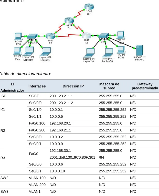
Escenario 1:
Tabla de direccionamiento:
El
Administrador
Interfaces Dirección IP Máscara de subred predeterminado Gateway
ISP S0/0/0 200.123.211.1 255.255.255.0 N/D
R1
Se0/0/0 200.123.211.2 255.255.255.0 N/D
Se0/1/0 10.0.0.1 255.255.255.252 N/D
Se0/1/1 10.0.0.5 255.255.255.252 N/D
R2
Fa0/0,100 192.168.20.1 255.255.255.0 N/D
Fa0/0,200 192.168.21.1 255.255.255.0 N/D
Se0/0/0 10.0.0.2 255.255.255.252 N/D
Se0/0/1 10.0.0.9 255.255.255.252 N/D
R3
Fa0/0 192.168.30.1 255.255.255.0 N/D
2001:db8:130::9C0:80F:301 /64 N/D
Se0/0/0 10.0.0.6 255.255.255.252 N/D
Se0/0/1 10.0.0.10 255.255.255.252 N/D
SW2 VLAN 100 N/D N/D N/D
VLAN 200 N/D N/D N/D
6
PC20 NIC DHCP DHCP DHCP
PC21 NIC DHCP DHCP DHCP
PC30 NIC DHCP DHCP DHCP
PC31 NIC DHCP DHCP DHCP
Laptop20 NIC DHCP DHCP DHCP
Laptop21 NIC DHCP DHCP DHCP
Laptop30 NIC DHCP DHCP DHCP
Laptop31 NIC DHCP DHCP DHCP
Tabla de asignación de VLAN y de puertos:
Dispositivo VLAN Nombre Interfaz
SW2 100 LAPTOPS Fa0/2-3
SW2 200 DESTOPS Fa0/4-5
SW3 1 - Todas las interfaces
Tabla de enlaces troncales:
Dispositivo local Interfaz local Dispositivo remoto
SW2 Fa0/2-3 100
Situación
En esta actividad, demostrará y reforzará su capacidad para implementar NAT, servidor de DHCP, RIPV2 y el routing entre VLAN, incluida la configuración de direcciones IP, las VLAN, los enlaces troncales y las subinterfaces. Todas las pruebas de alcance deben realizarse a través de ping únicamente.
Descripción de las actividades
• SW1 VLAN y las asignaciones de puertos de VLAN deben cumplir con la tabla 1.
• Los puertos de red que no se utilizan se deben deshabilitar.
• La información de dirección IP R1, R2 y R3 debe cumplir con la tabla 1.
7 Switch>enable
Switch#configure terminal
Enter configuration commands, one per line. End with CNTL/Z. Switch(config)#hostname SW2 SW2(config)#vlan 100 SW2(config-vlan)#name LAPTOPS SW2(config-vlan)#vlan 200 SW2(config-vlan)#name DESTOPS SW2(config-vlan)#exit
SW2(config)#int range fa0/2-3
SW2(config-if-range)#switchport mode access SW2(config-if-range)#switchport access vlan 100 SW2(config-if-range)#int range fa0/4-5
SW2(config-if-range)#switchport mode access SW2(config-if-range)#switchport access vlan 200 SW2(config-if-range)#int fa0/1
SW2(config-if)#switchport mode trunk SW2(config-if)#
%LINEPROTO-5-UPDOWN: Line protocol on Interface FastEthernet0/1, changed state to down
%LINEPROTO-5-UPDOWN: Line protocol on Interface FastEthernet0/1, changed state to up
SW2(config-if)#int range fa0/6-24 SW2(config-if-range)#shutdown
%LINK-5-CHANGED: Interface FastEthernet0/6, changed state to administratively down
%LINK-5-CHANGED: Interface FastEthernet0/7, changed state to administratively down
%LINK-5-CHANGED: Interface FastEthernet0/8, changed state to administratively down
%LINK-5-CHANGED: Interface FastEthernet0/9, changed state to administratively down
%LINK-5-CHANGED: Interface FastEthernet0/10, changed state to administratively down
%LINK-5-CHANGED: Interface FastEthernet0/11, changed state to administratively down
%LINK-5-CHANGED: Interface FastEthernet0/12, changed state to administratively down
%LINK-5-CHANGED: Interface FastEthernet0/13, changed state to administratively down
%LINK-5-CHANGED: Interface FastEthernet0/14, changed state to administratively down
8
%LINK-5-CHANGED: Interface FastEthernet0/16, changed state to administratively down
%LINK-5-CHANGED: Interface FastEthernet0/17, changed state to administratively down
%LINK-5-CHANGED: Interface FastEthernet0/18, changed state to administratively down
%LINK-5-CHANGED: Interface FastEthernet0/19, changed state to administratively down
%LINK-5-CHANGED: Interface FastEthernet0/20, changed state to administratively down
%LINK-5-CHANGED: Interface FastEthernet0/21, changed state to administratively down
%LINK-5-CHANGED: Interface FastEthernet0/22, changed state to administratively down
%LINK-5-CHANGED: Interface FastEthernet0/23, changed state to administratively down
%LINK-5-CHANGED: Interface FastEthernet0/24, changed state to administratively down
SW2(config-if-range)#exit Ahora, procedemos a configurar R2: Router>enable
Router#configure terminal
Enter configuration commands, one per line. End with CNTL/Z. Router(config)#hostname R2
R2(config)#int f0/0.100 R2(config-subif)#
%LINK-5-CHANGED: Interface FastEthernet0/0.100, changed state to up
%LINEPROTO-5-UPDOWN: Line protocol on Interface FastEthernet0/0.100, changed state to up
R2(config-subif)#encapsulation dot1Q 100
R2(config-subif)#ip address 192.168.20.1 255.255.255.0 R2(config-subif)#int f0/0.200
R2(config-subif)#
%LINK-5-CHANGED: Interface FastEthernet0/0.200, changed state to up
%LINEPROTO-5-UPDOWN: Line protocol on Interface FastEthernet0/0.200, changed state to up
R2(config-subif)#encapsulation dot1Q 200
R2(config-subif)#ip address 192.168.21.1 255.255.255.0 R2(config-subif)#int f0/0
R2(config-if)#no shutdown R2(config-if)#int s0/0/0
9 R2(config-if)#int s0/0/1
R2(config-if)#ip address 10.0.0.9 255.255.255.252 R2(config-if)#no shutdown
Ahora, procedemos a configurar R1: Router>enable
Router#configure terminal
Enter configuration commands, one per line. End with CNTL/Z. Router(config)#hostname R1
R1(config)#int s0/0/0
R1(config-if)#ip address 200.123.211.2 255.255.255.0 R1(config-if)#no shutdown
R1(config-if)#int s0/1/0
R1(config-if)#ip address 10.0.0.1 255.255.255.252 R1(config-if)#no shutdown
R1(config-if)#int s0/1/1
R1(config-if)#ip address 10.0.0.5 255.255.255.252 R1(config-if)#no shutdown
Ahora, procedemos a configurar R3: Router>enable
Router#configure terminal
Enter configuration commands, one per line. End with CNTL/Z. Router(config)#hostname R3
R3(config)#ipv6 unicast-routing R3(config)#int f0/0
R3(config-if)#ip address 192.168.30.1 255.255.255.0 R3(config-if)#ipv6 address 2001:db8:130::9C0:80F:301/64 R3(config-if)#ipv6 dhcp server vlan 1
R3(config-if)#ipv6 nd other-config-flag R3(config-if)#no shutdown
R3(config-if)#int s0/0/0
R3(config-if)#ip address 10.0.0.6 255.255.255.252 R3(config-if)#no shutdown
R3(config-if)#int s0/0/1
R3(config-if)#ip address 10.0.0.10 255.255.255.252 R3(config-if)#no shutdown
Hasta este punto se han hecho las configuraciones respectivas para los tres primeros puntos.
• Laptop20, Laptop21, PC20, PC21, Laptop30, Laptop31, PC30 y PC31 deben obtener información IPv4 del servidor DHCP.
Ahora, nos disponemos a configurar el servidor DHCP: En R2:
10 R2#configure terminal
Enter configuration commands, one per line. End with CNTL/Z. R2(config)#ip dhcp pool vlan 100
R2(dhcp-config)#network 192.168.20.1 255.255.255.0 R2(dhcp-config)#default-router 192.168.20.1
R2(dhcp-config)#ip dhcp pool vlan 200
R2(dhcp-config)#network 192.168.21.1 255.255.255.0 R2(dhcp-config)#default-router 192.168.21.1
R2(config)#int f0/0
R2(config-if)#no shutdown
En R3:
R3(config)#ip dhcp pool vlan_1
R3(dhcp-config)#network 192.168.30.1 255.255.255.0 R3(dhcp-config)#default-router 192.168.30.1
R3(dhcp-config)#ipv6 dhcp pool vlan_1
R3(config-dhcpv6)#dns-server 2001:db8:130:: R3(config-dhcpv6)#exit
• R1 debe realizar una NAT con sobrecarga sobre una dirección IPv4 pública. Asegúrese de que todos los terminales pueden comunicarse con Internet pública (haga ping a la dirección ISP) y la lista de acceso estándar se llama INSIDE-DEVS.
R1(config)#int s0/1/1
R1(config-if)#ip nat inside R1(config-if)#exit
R1(config)#int s0/1/0
R1(config-if)#ip nat inside R1(config-if)#exit
R1(config)#int s0/0/0
R1(config-if)#ip nat outside R1(config-if)#exit
R1(config)#ip nat pool INSIDE-DEVS 200.123.211.2 200.123.211.128 netmask 255.255.255.0
R1(config)#access-list 1 permit 192.168.0.0 0.0.255.255 R1(config)#access-list 1 permit 10.0.0.0 0.255.255.255 R1(config)#ip nat inside source list 1 interface s0/0/0 overload
R1(config)#ip nat inside source static tcp 192.168.30.6 80 200.123.211.1 80
R1(config)#exit
11
configuró y que incluye esa ruta en el dominio RIPv2. Configuraré, inicialmente, R1, luego R2 y por último R3:
R1(config)#router rip
R1(config-router)#version 2
R1(config-router)#ip route 0.0.0.0 0.0.0.0 s0/0/0 R1(config)#router rip
R1(config-router)#network 10.0.0.4 R1(config-router)#network 10.0.0.0
R1(config-router)#default-information originate
R2(config)#router rip
R2(config-router)#version 2
R2(config-router)#network 192.168.30.0 R2(config-router)#network 192.168.20.0 R2(config-router)#network 192.168.21.0 R2(config-router)#network 10.0.0.0 R2(config-router)#network 10.0.0.8
R3(config)#router rip
R3(config-router)#version 2
R3(config-router)#network 192.168.0.0 R3(config-router)#network 10.0.0.8 R3(config-router)#network 10.0.0.4 R3(config-router)#exit
• R2 es un servidor de DHCP para los dispositivos conectados al puerto FastEthernet0/0.
R2(config)#ip dhcp excluded-address 10.0.0.2 10.0.0.9 R2(config)#ip dhcp pool INSIDE-DEV
R2(dhcp-config)#network 192.168.20.1 255.255.255.0 R2(dhcp-config)#network 192.168.21.1 255.255.255.0 R2(dhcp-config)#default router 192.168.1.1
^
% Invalid input detected at '^' marker. R2(dhcp-config)#default-router 192.168.1.1 R2(dhcp-config)#dns-server 0.0.0.0
R2(dhcp-config)#exit
12 R2(config)#int vlan 100
R2(config-if)#ip address 192.168.20.1 255.255.255.0 R2(config)#int vlan 200
R2(config-if)#ip address 192.168.21.1 255.255.255.0 R2(config-if)#exit
• El Servidor0 es sólo un servidor IPv6 y solo debe ser accesibles para los dispositivos en R3 (ping).
• La NIC instalado en direcciones IPv4 e IPv6 de Laptop30, de Laptop31, de PC30 y obligación de configurados PC31 simultáneas (dual-stack). Las direcciones se deben configurar mediante DHCP y DHCPv6.
Ya están habilitadas.
• La interfaz FastEthernet 0/0 del R3 también deben tener direcciones IPv4 e IPv6 configuradas (dual- stack).
R3(config)#ipv6 unicast-routing R3(config)#int f0/0
R3(config-if)#ipv6 enable
R3(config-if)#ip address 192.168.30.1 % Incomplete command.
13 R3(config-if)#no shutdown
R1(config)#router rip
R1(config-router)#network 10.0.0.0 R1(config-router)#network 10.0.0.4 R1(config-router)#exit
R2(config)#router rip
R2(config-router)#version 2
R2(config-router)#network 10.0.0.0 R2(config-router)#network 10.0.0.8 R2(config-router)#exit
R2(config)#do show ip route connected
C 10.0.0.0/30 is directly connected, Serial0/0/0 C 10.0.0.8/30 is directly connected, Serial0/0/1
C 192.168.20.0/24 is directly connected, FastEthernet0/0.100 C 192.168.21.0/24 is directly connected, FastEthernet0/0.200
R3(config-if)#router rip R3(config-router)#version 2
R3(config-router)#network 10.0.0.0 R3(config-router)#network 10.0.0.8 R3(config-router)#end
R3#
%SYS-5-CONFIG_I: Configured from console by console R3#show ip route connected
C 10.0.0.4/30 is directly connected, Serial0/0/0 C 10.0.0.8/30 is directly connected, Serial0/0/1
C 192.168.30.0/24 is directly connected, FastEthernet0/0
• R1, R2 y R3 intercambian información de routing mediante RIP versión 2.
Este paso va incluido en el paso anterior (router rip, version 2).
• R1, R2 y R3 deben saber sobre las rutas de cada uno y la ruta predeterminada desde R1.
14
• Verifique la conectividad. Todos los terminales deben poder hacer ping entre sí y a la dirección IP del ISP. Los terminales bajo el R3 deberían poder hacer IPv6-ping entre ellos y el servidor.
15 Desde otros terminales también es exitoso:
17 Escenario 2:
Una empresa de Tecnología posee tres sucursales distribuidas en las ciudades de Miami, Bogotá y Buenos Aires, en donde el estudiante será el administrador de la red, el cual deberá configurar e interconectar entre sí cada uno de los dispositivos que forman parte del escenario, acorde con los lineamientos establecidos para el direccionamiento IP, protocolos de enrutamiento y demás aspectos que forman parte de la topología de red.
1. Configurar el direccionamiento IP acorde con la topología de red para cada uno de los dispositivos que forman parte del escenario.
Configuramos los equipos de la siguiente manera:
- Internet PC: Doble clic en el equipo, luego ir al apartado, Desktop, luego a IP Configuration y por último agregar la siguiente información: IP Address: 209.165.200.230; Subnet Mask: 255.255.255.248; y Default Gateway: 209.165.200.225.
- R1: Doble clic en el router, ir al apartado CLI y configurar de la siguiente manera:
Router>enable
Router#configure terminal
Enter configuration commands, one per line. End with CNTL/Z. Desactivar el Lookup
Router(config)#no ip domain-lookup Cambiar el nombre al router
Router(config)#hostname R1 Activar las contraseñas
18 R1(config)#line con 0
R1(config-line)#pass cisco R1(config-line)#login
R1(config-line)#line vty 0 4 R1(config-line)#pass cisco R1(config-line)#login
R1(config-line)#exit
Activar el service password-encryption, el mensaje del día y la s0/0/0 R1(config)#service password-encryption
R1(config)#banner motd #
Enter TEXT message. End with the character '#'. Unauthorized Access is Prohibited.#
R1(config)#int s0/0/0
R1(config-if)#ip address 172.31.21.1 255.255.255.252 R1(config-if)#clockrate 128000
- R2: Doble clic en el router, ir al apartado CLI y configurar de la siguiente manera:
Router>enable
Router#configure terminal
Enter configuration commands, one per line. End with CNTL/Z. Desactivar el Lookup
Router(config)#no ip domain-lookup Cambiar el nombre al router
Router(config)#hostname R2 Activar las contraseñas
R2(config)#enable secret class R2(config)#line con 0
R2(config-line)#pass cisco R2(config-line)#login
R2(config-line)#line vty 0 4 R2(config-line)#pass cisco R2(config-line)#login
R2(config-line)#exit
Activar el service password-encryption, el mensaje del día y las interfaces R2(config)#service password-encryption
R2(config)#banner motd #
Enter TEXT message. End with the character '#'. Unauthorized Access is Prohibited.#
R2(config)#int s0/0/0
R2(config-if)#description Connection to R1
R2(config-if)#ip address 172.31.21.2 255.255.255.252 R2(config-if)#no shutdown
R2(config-if)#
19
%LINEPROTO-5-UPDOWN: Line protocol on Interface Serial0/0/0, changed state to up
R2(config-if)#int s0/0/1
R2(config-if)#description Connection to R3
R2(config-if)#ip address 172.31.23.1 255.255.255.252 R2(config-if)#clock rate 128000
R2(config-if)#no shutdown
%LINK-5-CHANGED: Interface Serial0/0/1, changed state to down R2(config-if)# int g0/0
R2(config-if)#description Connection to ISP
R2(config-if)#ip address 209.165.200.225 255.255.255.248 R2(config-if)#no shutdown
R2(config-if)#
%LINK-5-CHANGED: Interface GigabitEthernet0/0, changed state to up
%LINEPROTO-5-UPDOWN: Line protocol on Interface GigabitEthernet0/0, changed state to up
R2(config)#int g0/1
R2(config-if)#ip address 10.10.10.1 255.255.255.0 R2(config-if)#no shutdown
R2(config-if)#
%LINK-5-CHANGED: Interface GigabitEthernet0/1, changed state to up
%LINEPROTO-5-UPDOWN: Line protocol on Interface GigabitEthernet0/1, changed state to up
R2(config-if)#description Connection to Web Server R2(config-if)#exit
R2(config)#ip route 0.0.0.0 0.0.0.0 g0/0
- Web Server: Doble clic en el servidor, luego ir al apartado, Desktop, luego a IP Configuration y por último agregar la siguiente información: IP Address: 10.10.10.10; Subnet Mask: 255.255.255.0; y Default Gateway: 10.10.10.1.
- R3: Doble clic en el router, ir al apartado CLI y configurar de la siguiente manera: Router>enable
Router#configure terminal
Enter configuration commands, one per line. End with CNTL/Z. Desactivar el Lookup
Router(config)#no ip domain-lookup Cambiar el nombre al router
Router(config)#hostname R3 Activar las contraseñas
R3(config)#enable secret class R3(config)#line con 0
R3(config-line)#pass cisco R3(config-line)#login
20 R3(config-line)#pass cisco
R3(config-line)#login R3(config-line)#exit
Activar el service password-encryption, el mensaje del día y las interfaces R3(config)#service password-encryption
R3(config)#banner motd #
Enter TEXT message. End with the character '#'. Unauthorized Access is Prohibited.#
R3(config)#int s0/0/1
R3(config-if)#description Connection to R2
R3(config-if)#ip address 172.31.23.2 255.255.255.252 R3(config-if)#no shutdown
R3(config-if)#
%LINK-5-CHANGED: Interface Serial0/0/1, changed state to up R3(config-if)#int lo4
R3(config-if)#
%LINK-5-CHANGED: Interface Loopback4, changed state to up %LINEPROTO-5-UPDOWN: Line protocol on Interface Loopback4, changed state to up
R3(config-if)#ip address 192.168.4.1 255.255.255.0 R3(config-if)#no shutdown
R3(config-if)#int lo5
%LINK-5-CHANGED: Interface Loopback5, changed state to up %LINEPROTO-5-UPDOWN: Line protocol on Interface Loopback5, changed state to up
R3(config-if)#ip address 192.168.5.1 255.255.255.0 R3(config-if)#no shutdown
R3(config-if)#int lo6
%LINK-5-CHANGED: Interface Loopback6, changed state to up %LINEPROTO-5-UPDOWN: Line protocol on Interface Loopback6, changed state to up
R3(config-if)#ip address 192.168.6.1 255.255.255.0 R3(config-if)#exit
R3(config)#ip route 0.0.0.0 0.0.0.0 s0/0/1
- S1: Doble clic en el switch, ir al apartado CLI y configurar de la siguiente manera: Switch>enable
Switch#configure terminal
Enter configuration commands, one per line. End with CNTL/Z. Desactivar el Lookup
Switch(config)#no ip domain-lookup Cambiar el nombre al router
Switch(config)#hostname S1 Activar las contraseñas
21 S1(config-line)#pass cisco
S1(config-line)#login
S1(config-line)#line vty 0 4 S1(config-line)#pass cisco S1(config-line)#login
Activar el service password-encryption, el mensaje del día S1(config-line)#service password-encryption S1(config)#banner motd #
Enter TEXT message. End with the character '#'. Unauthorized Access is Prohibited.#
- S3: Doble clic en el switch, ir al apartado CLI y configurar de la siguiente manera: Switch>enable
Switch#configure terminal
Enter configuration commands, one per line. End with CNTL/Z. Desactivar el Lookup
Switch(config)#no ip domain-lookup Cambiar el nombre al router
Switch(config)#hostname S3 Activar las contraseñas
S3(config)#enable secret class S3(config)#line con 0
S3(config-line)#pass cisco S3(config-line)#login
S3(config-line)#line vty 0 4 S3(config-line)#pass cisco S3(config-line)#login
Activar el service password-encryption, el mensaje del día S3(config-line)#service password-encryption S3(config)#banner motd #
Enter TEXT message. End with the character '#'. Unauthorized Access is Prohibited.#
Nota: Debemos recordar que como Packet Tracer no soporta el comando ip http server, ponemos un Web Server físico en la topología.
22
2. Configurar el protocolo de enrutamiento OSPFv2 bajo los siguientes criterios:
OSPFv2 area 0
Configuration Item or Task Specification
Router ID R1 1.1.1.1
Router ID R2
5.5.5.5 Router ID R3
8.8.8.8 Configurar todas las interfaces LAN como pasivas
Establecer el ancho de banda para enlaces seriales en 256 Kb/s Ajustar el costo en la métrica de S0/0 a 9500
Comenzamos la configuración en el siguiente orden:
- R1: Doble clic en el router, ir al apartado CLI y configurar de la siguiente manera: R1>enable
R1#configure terminal
Enter configuration commands, one per line. End with CNTL/Z. R1(config)#router ospf 1
R1(config-router)#router-id 1.1.1.1
R1(config-router)#network 172.31.21.0 0.0.0.3 area 0 R1(config-router)#network 192.168.30.0 0.0.0.255 area 0 R1(config-router)#network 192.168.40.0 0.0.0.255 area 0 R1(config-router)#network 192.168.200.0 0.0.0.255 area 0 R1(config-router)#passive-interface g0/1.30
23 R1(config-router)#exit
R1(config)#int s0/0/0
R1(config-if)#bandwidth 256 R1(config-if)#ip ospf cost 9500
- R2: Doble clic en el router, ir al apartado CLI y configurar de la siguiente manera: R2>enable
R2#configure terminal
Enter configuration commands, one per line. End with CNTL/Z. R2(config)#router ospf 1
R2(config-router)#router-id 5.5.5.5
R2(config-router)#network 172.31.21.0 0.0.0.3 area 0 R2(config-router)#
05:27:37: %OSPF-5-ADJCHG: Process 1, Nbr 1.1.1.1 on Serial0/0/0 from LOADING to FULL, Loading Done
R2(config-router)#network 172.31.23.0 0.0.0.3 area 0 R2(config-router)#network 10.10.10.0 0.0.0.255 area 0 R2(config-router)#passive-interface g0/1
R2(config-router)#int s0/0/0 R2(config-if)#bandwidth 256 R2(config-if)#int s0/0/1 R2(config-if)#bandwidth 256 R2(config-if)#int s0/0/0
R2(config-if)#ip ospf cost 9500
- R3: Doble clic en el router, ir al apartado CLI y configurar de la siguiente manera: R3>enable
R3#configure terminal
Enter configuration commands, one per line. End with CNTL/Z. R3(config)#router ospf 1
R3(config-router)#router-id 8.8.8.8
R3(config-router)#network 172.31.23.0 0.0.0.3 area 0 R3(config-router)#network 172.31.23.0 0.0.0.3 area 0 05:39:11: %OSPF-5-ADJCHG: Process 1, Nbr 5.5.5.5 on Serial0/0/1 from LOADING to FULL, Loading Done
R3(config-router)#network 192.168.4.0 0.0.3.255 area 0 R3(config-router)#passive-interface lo4
R3(config-router)#passive-interface lo5 R3(config-router)#passive-interface lo6 R3(config-router)#int s0/0/1
24 Verificar información de OSPF
25
• Visualizar lista resumida de interfaces por OSPF en donde se ilustre el costo de cada interface Utilicé el comando show run
• Visualizar el OSPF Process ID, Router ID, Address summarizations, Routing Networks, and passive interfaces configuradas en cada router.
26
Para hacer las configuraciones, iniciamos con cada uno de los switches:
- S1: Doble clic en el switch, ir al apartado CLI y configurar de la siguiente manera: S1>enable
S1#configure terminal
Enter configuration commands, one per line. End with CNTL/Z. S1(config)#vlan 30 S1(config-vlan)#name Administracion S1(config-vlan)#vlan 40 S1(config-vlan)#name Mercadeo S1(config-vlan)#vlan 200 S1(config-vlan)#name Mantenimiento S1(config-vlan)#exit
S1(config)#int vlan 30
%LINK-5-CHANGED: Interface Vlan30, changed state to up S1(config-if)#ip address 192.168.99.2 255.255.255.0 S1(config-if)#no shutdown
S1(config-if)#exit
S1(config)#ip default-gateway 192.168.99.1 S1(config)#int f0/3
S1(config-if)#switchport mode trunk S1(config-if)#
%LINEPROTO-5-UPDOWN: Line protocol on Interface FastEthernet0/3, changed state to down
%LINEPROTO-5-UPDOWN: Line protocol on Interface FastEthernet0/3, changed state to up
%LINEPROTO-5-UPDOWN: Line protocol on Interface Vlan30, changed state to up
S1(config-if)#switchport trunk native vlan 1 S1(config)#int f0/24
S1(config-if)#switchport mode trunk
S1(config-if)#switchport trunk native vlan 1
S1(config-if)#int range fa0/1-2, fa0/4-23, g0/1-2 S1(config)#switchport mode access
S1(config-if-range)#int fa0/1
S1(config-if)#switchport mode access S1(config-if)#switchport acces vlan 30
S1(config-if)#int range fa0/2, fa0/4-23, g0/1-2 S1(config-if-range)#shutdown
%LINK-5-CHANGED: Interface FastEthernet0/2, changed state to administratively down
%LINK-5-CHANGED: Interface FastEthernet0/4, changed state to administratively down
27
%LINK-5-CHANGED: Interface FastEthernet0/6, changed state to administratively down
%LINK-5-CHANGED: Interface FastEthernet0/7, changed state to administratively down
%LINK-5-CHANGED: Interface FastEthernet0/8, changed state to administratively down
%LINK-5-CHANGED: Interface FastEthernet0/9, changed state to administratively down
%LINK-5-CHANGED: Interface FastEthernet0/10, changed state to administratively down
%LINK-5-CHANGED: Interface FastEthernet0/11, changed state to administratively down
%LINK-5-CHANGED: Interface FastEthernet0/12, changed state to administratively down
%LINK-5-CHANGED: Interface FastEthernet0/13, changed state to administratively down
%LINK-5-CHANGED: Interface FastEthernet0/14, changed state to administratively down
%LINK-5-CHANGED: Interface FastEthernet0/15, changed state to administratively down
%LINK-5-CHANGED: Interface FastEthernet0/16, changed state to administratively down
%LINK-5-CHANGED: Interface FastEthernet0/17, changed state to administratively down
%LINK-5-CHANGED: Interface FastEthernet0/18, changed state to administratively down
%LINK-5-CHANGED: Interface FastEthernet0/19, changed state to administratively down
%LINK-5-CHANGED: Interface FastEthernet0/20, changed state to administratively down
%LINK-5-CHANGED: Interface FastEthernet0/21, changed state to administratively down
%LINK-5-CHANGED: Interface FastEthernet0/22, changed state to administratively down
%LINK-5-CHANGED: Interface FastEthernet0/23, changed state to administratively down
%LINK-5-CHANGED: Interface GigabitEthernet0/1, changed state to administratively down
%LINK-5-CHANGED: Interface GigabitEthernet0/2, changed state to administratively down
- S3: Doble clic en el switch, ir al apartado CLI y configurar de la siguiente manera: S3>enable
S3#configure terminal
28 S3(config-vlan)#name Administracion S3(config-vlan)#vlan 40 S3(config-vlan)#name Mercadeo S3(config-vlan)#vlan 200 S3(config-vlan)#name Mantenimiento S3(config-vlan)#exit
S3(config)#int vlan 30
%LINK-5-CHANGED: Interface Vlan30, changed state to up %LINEPROTO-5-UPDOWN: Line protocol on Interface Vlan30, changed state to up
S3(config-if)#ip address 192.168.99.3 255.255.255.0 S3(config-if)#no shutdown
S3(config-if)#exit
S3(config)#ip default-gateway 192.168.99.1 S3(config)#int fa0/3
S3(config-if)#switchport mode trunk
S3(config-if)#switchport trunk native vlan 1
S3(config-if)#int range fa0/1-2, fa0/4-24, g0/1-2 S3(config-if-range)#switchport mode access
S3(config-if-range)#int fa0/1
S3(config-if)#switchport mode access S3(config-if)#switchport access vlan 40
S3(config-if)#int range fa0/2, fa0/4-24, g0/1-2 S3(config-if-range)#shutdown
%LINK-5-CHANGED: Interface FastEthernet0/2, changed state to administratively down
%LINK-5-CHANGED: Interface FastEthernet0/4, changed state to administratively down
%LINK-5-CHANGED: Interface FastEthernet0/5, changed state to administratively down
%LINK-5-CHANGED: Interface FastEthernet0/6, changed state to administratively down
%LINK-5-CHANGED: Interface FastEthernet0/7, changed state to administratively down
%LINK-5-CHANGED: Interface FastEthernet0/8, changed state to administratively down
%LINK-5-CHANGED: Interface FastEthernet0/9, changed state to administratively down
%LINK-5-CHANGED: Interface FastEthernet0/10, changed state to administratively down
%LINK-5-CHANGED: Interface FastEthernet0/11, changed state to administratively down
29
%LINK-5-CHANGED: Interface FastEthernet0/13, changed state to administratively down
%LINK-5-CHANGED: Interface FastEthernet0/14, changed state to administratively down
%LINK-5-CHANGED: Interface FastEthernet0/15, changed state to administratively down
%LINK-5-CHANGED: Interface FastEthernet0/16, changed state to administratively down
%LINK-5-CHANGED: Interface FastEthernet0/17, changed state to administratively down
%LINK-5-CHANGED: Interface FastEthernet0/18, changed state to administratively down
%LINK-5-CHANGED: Interface FastEthernet0/19, changed state to administratively down
%LINK-5-CHANGED: Interface FastEthernet0/20, changed state to administratively down
%LINK-5-CHANGED: Interface FastEthernet0/21, changed state to administratively down
%LINK-5-CHANGED: Interface FastEthernet0/22, changed state to administratively down
%LINK-5-CHANGED: Interface FastEthernet0/23, changed state to administratively down
%LINK-5-CHANGED: Interface FastEthernet0/24, changed state to administratively down
%LINK-5-CHANGED: Interface GigabitEthernet0/1, changed state to administratively down
%LINK-5-CHANGED: Interface GigabitEthernet0/2, changed state to administratively down
S3(config-if-range)#end
- R1: Doble clic en el router, ir al apartado CLI y configurar de la siguiente manera:
R1>enable Password:
R1#configure terminal
Enter configuration commands, one per line. End with CNTL/Z. R1(config)#int g0/1.40
R1(config-subif)#description Mercadeo LAN R1(config-subif)#encapsulation dot1q 40
R1(config-subif)#ip address 192.168.40.1 255.255.255.0 R1(config-subif)#int g0/1.30
R1(config-subif)#description Administracion LAN R1(config-subif)#encapsulation dot1q 30
R1(config-subif)#ip address 192.168.30.1 255.255.255.0 R1(config-subif)#int g0/1.200
30
R1(config-subif)#ip address 192.168.200.1 255.255.255.0 R1(config-subif)#exit
R1(config)#int g0/1
R1(config-if)#no shutdown R1(config-if)#
%LINK-5-CHANGED: Interface GigabitEthernet0/1, changed state to up
%LINEPROTO-5-UPDOWN: Line protocol on Interface GigabitEthernet0/1, changed state to up
%LINK-5-CHANGED: Interface GigabitEthernet0/1.30, changed state to up
%LINEPROTO-5-UPDOWN: Line protocol on Interface GigabitEthernet0/1.30, changed state to up
%LINK-5-CHANGED: Interface GigabitEthernet0/1.40, changed state to up
%LINEPROTO-5-UPDOWN: Line protocol on Interface GigabitEthernet0/1.40, changed state to up
%LINK-5-CHANGED: Interface GigabitEthernet0/1.200, changed state to up
%LINEPROTO-5-UPDOWN: Line protocol on Interface GigabitEthernet0/1.200, changed state to up
3. En el Switch 3 deshabilitar DNS lookup
Ya este paso se realizó anteriormente. En las configuraciones iniciales se le dio al S3 el comando no ip domain-lookup.
4. Asignar direcciones IP a los Switches acorde a los lineamientos.
Ya este paso fue realizado previamente. Revisar código en el aparte de cada switch que contiene el comando ip address.
5. Desactivar todas las interfaces que no sean utilizadas en el esquema de red.
Ya este paso fue realizado previamente. Revisar código en el aparte que contiene los comandos int range y donde se indican las interfaces que se desactivan administrativamente (changed state to
administratively down) después de introducir el comando shutdown. 6. Desactivar todas las interfaces que no sean utilizadas en el esquema de
red.
Ya este paso fue realizado previamente. Revisar código en el aparte que contiene los comandos int range y donde se indican las interfaces que se desactivan administrativamente (changed state to
administratively down) después de introducir el comando shutdown. 7. Desactivar todas las interfaces que no sean utilizadas en el esquema de
31
Ya este paso fue realizado previamente. Revisar código en el aparte que contiene los comandos int range y donde se indican las interfaces que se desactivan administrativamente (changed state to
administratively down) después de introducir el comando shutdown. 8. Implementar DHCP y NAT para IPv4
9. Configurar R1 como servidor DHCP para las VLANs 30 y 40. 10. Reservar las primeras 30 direcciones IP de las VLAN 30 y 40 para
configuraciones estáticas.
Configurar DHCP pool para VLAN 30
Name: ADMINISTRACION DNS-Server: 10.10.10.11 Domain-Name: ccna-unad.com Establecer default gateway.
Configurar DHCP pool para VLAN 40
Name: MERCADEO DNS-Server: 10.10.10.11 Domain-Name: ccna-unad.com Establecer default gateway.
Las configuraciones de los puntos 8, 9 y 10 se hacen a continuación y en secuencia. Comenzamos inicialmente configurando R1:
- R1: Doble clic en el router, ir al apartado CLI y configurar de la siguiente manera: R1>enable
R1#configure terminal
Enter configuration commands, one per line. End with CNTL/Z. R1(config)#ip dhcp excluded-address 192.168.30.1
192.168.30.30
R1(config)#ip dhcp excluded-address 192.168.40.1 192.168.40.30
R1(config)#ip dhcp pool ADMINISTRACION R1(dhcp-config)#dns-server 10.10.10.11 R1(dhcp-config)#domain-name ccna-unad.com
^ Packet tracer no soporta este comando % Invalid input detected at '^' marker.
R1(dhcp-config)#default-router 192.168.30.1
R1(dhcp-config)#network 192.168.30.0 255.255.255.0 R1(dhcp-config)#ip dhcp pool MERCADEO
R1(dhcp-config)#dns-server 10.10.10.11 R1(dhcp-config)#domain-name ccna-unad.com
^ Packet tracer no soporta este comando % Invalid input detected at '^' marker.
R1(dhcp-config)#default-router 192.168.40.1
32
11. Configurar NAT en R2 para permitir que los hosts puedan salir a internet 12. Configurar al menos dos listas de acceso de tipo estándar a su criterio en
para restringir o permitir tráfico desde R1 o R3 hacia R2.
13. Configurar al menos dos listas de acceso de tipo extendido o nombradas a su criterio en para restringir o permitir tráfico desde R1 o R3 hacia R2. Las configuraciones de los puntos 11, 12 y 13 están determinadas a continuación: R2>enable
R2#configure terminal
Enter configuration commands, one per line. End with CNTL/Z. R2(config)#user webuser privilege 15 secret cisco12345
R2(config)#ip http server
^ Packet tracer no soporta este comando % Invalid input detected at '^' marker.
R2(config)#ip nat inside source static 10.10.10.10 209.165.200.229
R2(config)#int g0/0
R2(config-if)#ip nat outside R2(config-if)#int g0/1
R2(config-if)#ip nat inside R2(config-if)#exit
R2(config)#access-list 1 permit 192.168.30.0 0.0.0.255 R2(config)#access-list 1 permit 192.168.40.0 0.0.0.255 R2(config)#access-list 1 permit 192.168.4.0 0.0.3.255 R2(config)#ip nat pool INTERNET 209.165.200.225
209.165.200.228 netmask 255.255.255.248
R2(config)#ip nat inside source list 1 pool INTERNET Ahora, configuramos las listas de control de acceso estándar en R2: R2>enable
R2#configure terminal
Enter configuration commands, one per line. End with CNTL/Z. R2(config)#ip access-list standard ADMIN-MGT
R2(config-std-nacl)#permit 172.31.21.1 0.0.0.0 R2(config-std-nacl)#exit
R2(config)#line vty 0 4
R2(config-line)#access-class ADMIN-MGT in Ahora, verificamos en R1:
R1#telnet 172.31.21.1
Trying 172.31.21.1 ...Open
Unauthorized Access is Prohibited. User Access Verification
33
[Connection to 172.31.21.1 closed by foreign host] R1#telnet 172.31.21.2
Trying 172.31.21.2 ...Open
Unauthorized Access is Prohibited. User Access Verification
Password: R2>enable Password: R2#exit
[Connection to 172.31.21.2 closed by foreign host] R1#
Ahora, configuramos las listas de acceso extendidas:
R2(config)#access-list 101 permit tcp any host 209.165.200.229 eq www
R2(config)#access-list 101 permit icmp any any echo-reply R2(config)#int g0/0
R2(config-if)#ip access-group 101 in R2(config-if)#int s0/0/0
R2(config-if)#ip access-group 101 out R2(config-if)#int s0/0/1
R2(config-if)#ip access-group 101 out R2(config-if)#int g0/1
R2(config-if)#ip access-group 101 out Es hora de probar la accesibilidad hacienda ping:
34
14. Verificar procesos de comunicación y redireccionamiento de tráfico en los routers mediante el uso de Ping y Traceroute.
Como podemos ver, a ejecutar el comando ping y el traceroute a las rutas de los demás router, estos se hacen exitosamente.
Nota: Para encontrar los archivos en Packet Tracer trabajados en los presentes ejercicios, seguir el siguiente enlace:
35 Conclusiones
La presente práctica nos permitió desarrollar cada una de las competencias adquiridas durante el diplomado presente, aunque esa vez se nos puso un reto diferente: demostrar las habilidades en la implementación de los códigos
36 Referencias bibliográficas
CISCO. Exploración de la red. Fundamentos de Networking. 2014. Recuperado de:
https://static-course-assets.s3.amazonaws.com/ITN50ES/module1/index.html#1.0.1.1
CISCO. (2014). Configuración de un sistema operativo de red. Fundamentos de Networking. 2014. Recuperado de:
https://static-course-assets.s3.amazonaws.com/ITN50ES/module2/index.html#2.0.1.1
CISCO. (2014). Capa de Transporte. Fundamentos de Networking. Recuperado de:
https://static-course-assets.s3.amazonaws.com/ITN50ES/module7/index.html#7.0.1.1
CISCO. (2014). Asignación de direcciones IP. Fundamentos de Networking. Recuperado de:
https://static-course-assets.s3.amazonaws.com/ITN50ES/module8/index.html#8.0.1.1
CISCO. (2014). Configuración y conceptos básicos de Switching. Principios de Enrutamiento y Conmutación. Recuperado de: https://static-course-assets.s3.amazonaws.com/RSE50ES/module2/index.html#2.0.1.1
CISCO. (2014). VLANs. Principios de Enrutamiento y Conmutación. Recuperado de:
https://static-course-assets.s3.amazonaws.com/RSE50ES/module3/index.html#3.0.1.1
CISCO. (2014). Enrutamiento Dinámico. Principios de Enrutamiento y Conmutación. Recuperado de:
https://static-course-assets.s3.amazonaws.com/RSE50ES/module7/index.html#7.0.1.1
CISCO. (2014). OSPF de una sola área. Principios de Enrutamiento y Conmutación. Recuperado de: