DIPLOMADO DE PROFUNDIZACIÓN CISCO PRUEBA DE HABILIDADES PRÁCTICAS CCNP
VIVIANA CATHERIN CASTELLANOS CARDENAS
UNIVERSIDAD NACIONAL ABIERTA Y A DISTANCIA UNAD
ESCUELA DE CIENCIAS BÁSICAS, TECNOLOGÍA E INGENIERÍA - ECBTI
INGENIERIA DE TELECOMUNICACIONES
YOPAL
DIPLOMADO DE PROFUNDIZACIÓN CISCO PRUEBA DE HABILIDADES PRÁCTICAS CCNP
VIVIANA CATHERIN CASTELLANOS
Diplomado de opción de grado presentado para optar el título de INGENIERO DE
TELECOMUNICACIONES
DIRECTOR:
MAGISTER GIOVANNI ALBERTO BRACHO
UNIVERSIDAD NACIONAL ABIERTA Y A DISTANCIA UNAD
ESCUELA DE CIENCIAS BÁSICAS, TECNOLOGÍA E INGENIERÍA - ECBTI
INGENIERIA DE TELECOMUNICACIONES
YOPAL
3
NOTA DE ACEPTACIÓN
_________________________
_________________________
_________________________
_________________________
_________________________
_________________________
_________________________
_________________________ Presidente del Jurado
_________________________ Jurado
_________________________ Jurado
4
AGRADECIMIENTOS
5
CONTENIDO
Lista de Tablas ... 6
Lista de Figuras ... 7
Glosario ... 8
Resumen ... 9
Abstract ... 9
Introducción ... 10
1. Escenario 1 ... 11
2. Escenario 2 ... 30
3. Conclusiones ... 47
Bibliografía ... 48
6
LISTA DE TABLAS
7
LISTA DE FIGURAS
Ilustración 1. Escenario 1 ... 11
Ilustración 2. Topología de red... 12
Ilustración 3. R1 Tabla de enrutamiento Ipv4 ... 20
Ilustración 4. R1 Tabla de enrutamiento Ipv6 ... 20
Ilustración 5. R2 Tabla de enrutamiento Ipv4 ... 21
Ilustración 6. R2 Tabla de enrutamiento Ipv6 ... 21
Ilustración 7. R3 Tabla de enrutamiento Ipv4 ... 22
Ilustración 8. R3 Tabla de enrutamiento Ipv6 ... 22
Ilustración 9. Ping Ipv4 desde R1 a R2 y R3 ... 23
Ilustración 10. Ping Ipv4 desde R2 a R1 y R3 ... 24
Ilustración 11. Ping Ipv4 desde R3 a R1 y R2 ... 25
Ilustración 12. Traceroute desde R1 a LAN R2 y R3 ... 25
Ilustración 13. Traceroute desde R2 a LAN R1 y R3 ... 26
Ilustración 14. Traceroute desde R3 a LAN R1 y R2 ... 26
Ilustración 15. Configuración R1 ... 27
Ilustración 16. Configuración R1 ... 27
Ilustración 17. Configuración R2 ... 27
Ilustración 18. Configuración R2 ... 28
Ilustración 19. Configuración R3 ... 28
Ilustración 20. Configuración R3 ... 29
Ilustración 21. Escenario 2 Topología de red ... 30
Ilustración 22. Verificación de VLANs en DSL1 ... 45
Ilustración 23. Verificación de VLANs en DSL2 ... 45
Ilustración 24. Verificación de Etherchannel en DSL1 ... 46
8 GLOSARIO
Packet Tracer: Es un programa de simulación de red que permite a los estudiantes experimentar con el comportamiento de la red y hacer preguntas de "qué pasaría si". Packet Tracer proporciona capacidades de simulación, visualización, autoría, evaluación y colaboración, y facilita la enseñanza y el aprendizaje de conceptos tecnológicos complejos. (Ecured)
GNS3: Graphic Network Simulation o Simulación Gráfica de Redes es un simulador gráfico de red que permite diseñar topologías de red complejas y poner en marcha simulaciones sobre ellos. Con GNS3 los usuarios tendrán la posibilidad de poder escoger cada uno de los elementos que llegarán a formar parte de una red informática. (Universidad Complutense Madrid)
Protocolos de red: Conjunto de normas standard que especifican el método para enviar y recibir datos entre varios ordenadores. Es una convención que controla o permite la conexión, comunicación, y transferencia de datos entre dos puntos finales. (Ecured)
Router: Un Router, también llamado enrutador o encaminador de paquetes, es un dispositivo que proporciona conectividad e interconexión entre redes informáticas. Se ocupa de enviar datos de una red a otra, es decir, interconectar subredes. (Centro de innovacion y soluciones empresariales tecnologicas)
Switch: Un switch es un dispositivo de propósito especial diseñado para resolver problemas de rendimiento en la red, debido a anchos de banda pequeños y embotellamientos. Opera en la capa 2 del modelo OSI y reenvía los paquetes en base a la dirección MAC. (Untiveros)
VLAN: Las VLAN proporcionan una manera de agrupar dispositivos dentro de una LAN. Un grupo de dispositivos dentro de una VLAN se comunica como si estuvieran conectados al mismo cable. Las VLAN se basan en conexiones lógicas, en lugar de conexiones físicas. (Walton)
IPv4: El Internet de Protocolo versión 4 (Ipv4) (Protocolo de Internet versión 4) es la cuarta versión del protocolo Internet (IP), y la primera en ser implementada a
gran escala. Ipv4 usa direcciones de 32 bits, limitándola a 232 = 4.294.967.296
9 RESUMEN
En la prueba de habilidades del diplomado CCNP, el estudiante desarrollará cada uno de los escenarios propuestos, en la cual se buscara que el estudiante amplié los conocimientos adquiridos en los laboratorios desarrollados en cada una de las unidades del curso, con el fin de que el futuro ingeniero en campo de soluciones en la prestación de servicio de telecomunicaciones. Dentro de los laboratorios del diplomado y los escenarios propuestos, se profundizaron la capa de enlace de datos y la capa de red del modelo OSI, un modelo esencial para solucionar y descartar fallas en una red.
En los dos escenarios que se desarrollarán, se implementaran protocolos de red de acuerdo a cada capa del modelo OSI; para la capa de enlace de datos, se encuentran los protocolos para crear VLAN, Etherchannel, SNMP, NTP, GLBP, entre otros. Para la capa de red, los protocolos de enrutamiento, OSPF, EIGRP, RIP, BGP, etc.
Palabras claves: protocolos, modelo OSI, red, VLAN, enrutamiento, laboratorios, escenarios.
ABSTRACT
In the CCNP diploma skills test, the student will develop each of the proposed scenarios, in which it will be sought that the student expand the knowledge acquired in the laboratories developed in each of the units of the course, so that the student future engineer in the field of solutions in the provision of telecommunications service. Within the diploma laboratories and the proposed scenarios, the data link layer and the OSI network layer were deepened, an essential model for solving and ruling out network failures.
In the two scenarios that will be developed, network protocols will be implemented according to each layer of the OSI model; For the data link layer, there are protocols to create VLAN, Etherchannel, SNMP, NTP, GLBP, among others. For the network layer, routing protocols, OSPF, EIGRP, RIP, BGP, etc.
10
INTRODUCCIÓN
El diplomado de profundización CISCO CCNP, consta de dos partes, en el cual el estudiante se prepara para afrontar en campo la variedad de protocolos de red que en la actualidad son operados en cada una de las capas de los modelos OSI y TCP. Para el desarrollo de la prueba de habilidades nos enfocaremos en los protocolos de enrutamiento que son configurados en los routers y los protocolos para administrar redes VLANs en los switches.
En la primera parte, respecto a la unidad 1 y 2 del curso de cisco CCNP, se relaciona con la configuración de los diversos protocolos de enrutamiento en los routers, entre ellos RIP, EIGRP, OSPF, utilizados de acuerdo a la topología y tamaño de la red, implementación en la solución soportada en el protocolo de enrutamiento configurado dentro de una red, por lo cual es la función principal de un ingeniero de telecomunicaciones dar solución ante las caídas o intermitencia de un servicio.
En la segunda parte, se profundizo la capa 2 del modelo OSI, en el cual hemos tratado de las comunicaciones e interconexión entre los dispositivos de capa 2, que son los switches o hub, en las cuales se ha realizado prácticas para la configuración dentro de un sistema de red, VLANs, configuración de protocolos entre ellos HSRP, VRRP, GLBP, SNMP.
11
Descripción de escenarios propuestos para la prueba de habilidades
1. ESCENARIO 1
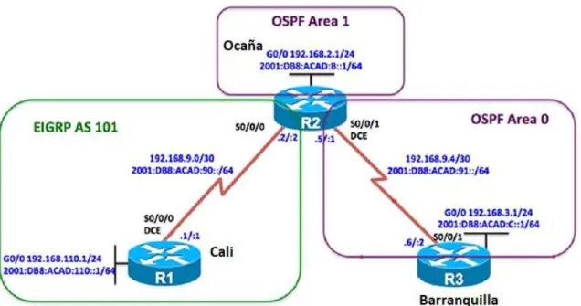
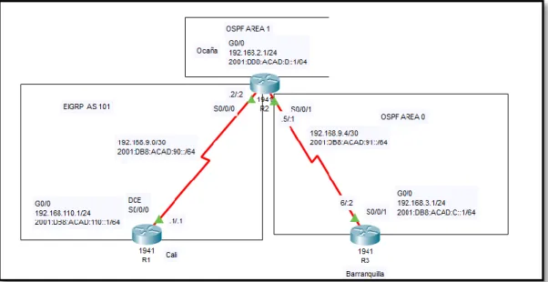
Una empresa de confecciones posee tres sucursales distribuidas en las ciudades de Cali, Barranquilla y Ocaña, en donde el estudiante será el administrador de la red, el cual deberá configurar e interconectar entre sí cada uno de los dispositivos que forman parte del escenario, acorde con los lineamientos establecidos para el direccionamiento IP, protocolos de enrutamiento y demás aspectos que forman parte de la topología de red.
Topología de red
12
Ilustración 2. Topología de red
Configurar la topología de red, de acuerdo con las siguientes especificaciones.
Parte 1: Configuración del escenario propuesto
1. Configurar las interfaces con las direcciones IPv4 e IPv6 que se muestran en la topología de red.
Solución
Configuración en R1
Router>en Router#config
Configuring from terminal, memory, or network [terminal]? Enter configuration commands, one per line. End with CNTL/Z. Router(config)#hostname R1
R1(config)#no ip domain-lookup R1(config)#line con 0
R1(config-line)#logging synchronous R1(config-line)#exec-timeout 0 0 R1(config)#interface g0/0
R1(config-if)#ip address 192.168.110.1 255.255.255.0 R1(config-if)#ipv6 address 2001:db8:acad:110::1/64 R1(config-if)#no shutdown
R1(config-if)#interface s0/0/0
R1(config-if)#ip address 192.168.9.1 255.255.255.252 R1(config-if)#ipv6 address 2001:db8:acad:90::1/64 R1(config-if)#clock rate 64000
13 Configuración en R2
Router>en Router#conf
Configuring from terminal, memory, or network [terminal]? Enter configuration commands, one per line. End with CNTL/Z. R2(config)#int g0/0
R2(config-if)#ip address 192.168.2.1 255.255.255.0 R2(config-if)#ipv6 address 2001:db8:acad:b::1/64 R2(config-if)#no shutdown
R2(config-if)#
%LINK-5-CHANGED: Interface GigabitEthernet0/0, changed state to up R2(config-if)#exit
R2(config)#int s0/0/0
R2(config-if)#ip address 192.168.9.2 255.255.255.252 R2(config-if)#ipv6 address 2001:db8:acad:90::2/64 R2(config-if)#no shutdown
R2(config-if)#
%LINK-5-CHANGED: Interface Serial0/0/0, changed state to up R2(config-if)#exit
R2(config)#
%LINEPROTO-5-UPDOWN: Line protocol on Interface Serial0/0/0, changed state to up
R2(config)#int s0/0/1
R2(config-if)#ip address 192.168.9.5 255.255.255.252 R2(config-if)#ipv6 address 2001:db8:acad:91::1/64 R2(config-if)#no shutdown
%LINK-5-CHANGED: Interface Serial0/0/1, changed state to down R2(config-if)#
Configuración en R3
Router>en Router#conf
Configuring from terminal, memory, or network [terminal]? Enter configuration commands, one per line. End with CNTL/Z. Router(config)#hostname R3
R3(config)#no ip domain-lookup R3(config)#line con 0
R3(config-line)#logging synchronous R3(config-line)#exit
R3(config)#int g0/0
14
R3(config-if)#ipv6 address 2001:db8:acad:c::1/64 R3(config-if)#no shutdown
R3(config-if)#
%LINK-5-CHANGED: Interface GigabitEthernet0/0, changed state to up R3(config-if)#exit
R3(config)#int s0/0/1
R3(config-if)#ip address 192.168.9.6 255.255.255.252 R3(config-if)#ipv6 address 2001:db8:acad:91::2/64 R3(config-if)#no shutdown
R3(config-if)#
%LINK-5-CHANGED: Interface Serial0/0/1, changed state to up R3(config-if)#
%LINEPROTO-5-UPDOWN: Line protocol on Interface Serial0/0/1, changed state to up
2. Ajustar el ancho de banda a 128 kbps sobre cada uno de los enlaces seriales ubicados en R1, R2, y R3 y ajustar la velocidad de reloj de las conexiones de DCE según sea apropiado.
Solución
Configuración en R1
R1(config)#int s0/0/0
R1(config-if)#bandwidth 128 R1(config-if)#clock rate 64000
Configuración en R2
R2(config)#int s0/0/0
R2(config-if)#bandwidth 128 R2(config-if)#ex
R2(config)#int s0/0/1
R2(config-if)#bandwidth 128 R2(config-if)#clock rate 64000
Configuración en R3
R3(config)#int s0/0/1
R3(config-if)#bandwidth 128
15 Solución
Configuración en R2
R2(config)#ipv6 unicast-routing R2(config)#router ospfv3 1 ^
% Invalid input detected at '^' marker. R2(config)#router ospf 1
R2(config-router)#address-family ipv4 unicast ^
% Invalid input detected at '^' marker.
R2(config-router)#router-id 2.2.2.2
R2(config-router)#address-family ipv6 unicast ^
% Invalid input detected at '^' marker.
Configuración en R3
R3(config)#ipv6 unicast-routing R3(config)#router ospfv3 1 ^
% Invalid input detected at '^' marker. R3(config)#router ospf 1
R3(config-router)#address-family ipv4 unicast ^
% Invalid input detected at '^' marker. R3(config-router)#router-id 3.3.3.3
R3(config-router)#address-family ipv6 unicast ^
% Invalid input detected at '^' marker.
4. En R2, configurar la interfaz F0/0 en el área 1 de OSPF y la conexión serial entre R2 y R3 en OSPF área 0.
Solución
Configuración en R2
R2(config-router)#int g0/0
R2(config-if)#ospfv3 1 ipv4 area 1 ^
16 % Invalid input detected at '^' marker.
R2(config-router)#int s0/0/1
R2(config-if)#ospfv3 1 ipv4 area 0 ^
% Invalid input detected at '^' marker. R2(config-if)#ospfv3 1 ipv6 area 0 ^
% Invalid input detected at '^' marker. R2(config)#router ospf 1
R2(config-router)#router-id 2.2.2.2 R2(config-router)#ex
R2(config)#int g0/0
R2(config-if)#ip ospf 1 area 1 R2(config-if)#ex
R2(config)#int s0/0/1
R2(config-if)#ip ospf 1 area 0
5. En R3, configurar la interfaz F0/0 y la conexión serial entre R2 y R3 en OSPF área 0.
Solución
Configuración en R3
R3(config-router)#int g0/0
R3(config-if)#ospfv3 1 ipv4 area 0 ^
% Invalid input detected at '^' marker. R3(config-if)#ospfv3 1 ipv6 area 0 ^
% Invalid input detected at '^' marker. R3(config-if)#ex
R3(config)#int s0/0/1
R3(config-if)#ospfv3 1 ipv4 area 0 ^
% Invalid input detected at '^' marker. R3(config-if)#ospfv3 1 ipv6 area 0 ^
% Invalid input detected at '^' marker.
R3(config)#router ospf 1
R3(config-router)#router-id 3.3.3.3 R3(config-router)#ex
R3(config)#int g0/0
17 R3(config-if)#ex
R3(config)#int s0/0/1
R3(config-if)#ip ospf 1 area 0
6. Configurar el área 1 como un área totalmente Stubby. Solución
Configuración en R2
R2(config)#router ospfv3 1 ^
% Invalid input detected at '^' marker. R2(config)#router ospf 1
R2(config-router)#address-family ipv4 unicast ^
% Invalid input detected at '^' marker. R2(config-router)#area 1 stub
R2(config-router)#address-family ipv6 unicast ^
% Invalid input detected at '^' marker. R2(config-router)#area 1 stub
7. Propagar rutas por defecto de IPv4 e IPv6 en R3 al interior del dominio OSPFv3. Nota: Es importante tener en cuenta que una ruta por defecto es diferente a la definición de rutas estáticas.
Solución
Configuración en R3
R3(config)#router ospfv3 1 ^
% Invalid input detected at '^' marker. R3(config)#router ospf 1
R3(config-router)#address-family ipv4 unicast ^
% Invalid input detected at '^' marker.
R3(config-router)#default-information originate R3(config-router)#address-family ipv6 unicast ^
% Invalid input detected at '^' marker.
R3(config-router)#default-information originate
R3(config)# router ospf 1
18
R3(config-router)# network 192.168.9.4 0.0.0.3 area 0
8. Realizar la configuración del protocolo EIGRP para IPv4 como IPv6. Configurar la interfaz F0/0 de R1 y la conexión entre R1 y R2 para EIGRP con el sistema autónomo 101. Asegúrese de que el resumen automático está desactivado.
Solución
Configuración en R1
R1(config)#ipv6 unicast-routing R1(config)#ipv6 router eigrp 101 R1(config-rtr)#eigrp router-id 1.1.1.1 R1(config-rtr)#no shutdown
R1(config-rtr)#exit R1(config)#int g0/0
R1(config-if)#ipv6 eigrp 101 R1(config-if)#exit
R1(config)#int s0/0/0
R1(config-if)#ipv6 eigrp 101 R1(config-if)#exit
R1(config)#router eigrp 101
R1(config-router)#no auto-summary R1(config-router)#exi
R1(config)# router eigrp 101
R1(config-router)# network 192.168.110.0 R1(config-router)# network 192.168.9.0
Configuración en R2
R2(config)#ipv6 unicast-routing R2(config)#ipv6 router eigrp 101 R2(config-rtr)#eigrp router-id 2.2.2.2 R2(config-rtr)#no shutdown
R2(config-rtr)#exit R2(config)#int s0/0/0
R2(config-if)#ipv6 eigrp 101 R2(config-if)#exit
R2(config)#router eigrp 101
R2(config-router)#no auto-summary R1(config)# router eigrp 101
R2(config-router)# network 192.168.9.0
19 Configuración en R1
R1(config)#ipv6 router eigrp 101 R1(config-rtr)#passive-interface g0/0 R1(config-rtr)#exit
R1(config)#router eigrp 101
R1(config-router)#passive-interface g0/0 R1(config-router)#exit
Configuración en R2
R2(config)#router ospf 1
R2(config-router)#passive-interface g0/0 R2(config-router)#ex
R2(config)#ipv6 router ospf 1
R2(config-rtr)#passive-interface g0/0 R2(config-rtr)#exit
R3(config)#router ospf 1
R3(config-router)#passive-interface g0/0 R3(config-router)#exit
R3(config)#ipv6 router ospf 1
R3(config-rtr)#passive-interface g0/0 R3(config-rtr)#exit
10. En R2, configurar la redistribución mutua entre OSPF y EIGRP para IPv4 e IPv6. Asignar métricas apropiadas cuando sea necesario.
Solución
Configuración en R2
R2(config)# router ospf 1
R2(config-router)# network 192.168.2.0 0.0.0.255 area 1 R2(config-router)# network 192.168.9.4 0.0.0.3 area 0 R2(config)#router ospf 1
R2(config-router)# redistribute eigrp 101 metric 10 subnet
R2(config-router)#%OSPF-4-ASBR_WITHOUT_VALID_AREA: Router is currently an ASBR while having only one area which is a stub area
R2(config-router)#exit R2(config)#router eigrp 101
R2(config-router)#redistribute ospf 1 metric 10000 100 255 1 1500 R2(config-router)#exit
20 Solución
Configuración en R2
R2(config)#ip access-list standard R2-to-R1
R2(config-std-nacl)#remark ACL to filter 192.168.3.0/24 R2(config-std-nacl)#deny 192.168.3.0 0.0.0.255
R2(config-std-nacl)#permit any
Parte 2: Verificar conectividad de red y control de la trayectoria.
a. Registrar las tablas de enrutamiento en cada uno de los router, acorde con los parámetros de configuración establecidos en el escenario propuesto. Solución
Ilustración 3. R1 Tabla de enrutamiento Ipv4
21
Ilustración 5. R2 Tabla de enrutamiento Ipv4
22
Ilustración 7. R3 Tabla de enrutamiento Ipv4
Ilustración 8. R3 Tabla de enrutamiento Ipv6
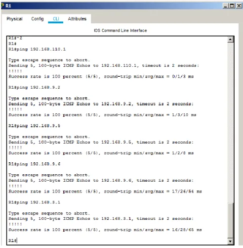
b. Verificar comunicación entre routers mediante el comando ping y traceroute
23
24
25
Ilustración 11. Ping Ipv4 desde R3 a R1 y R2
26
Ilustración 13. Traceroute desde R2 a LAN R1 y R3
Ilustración 14. Traceroute desde R3 a LAN R1 y R2
c. Verificar que las rutas filtradas no están presentes en las tablas de enrutamiento de los routers correctas.
27
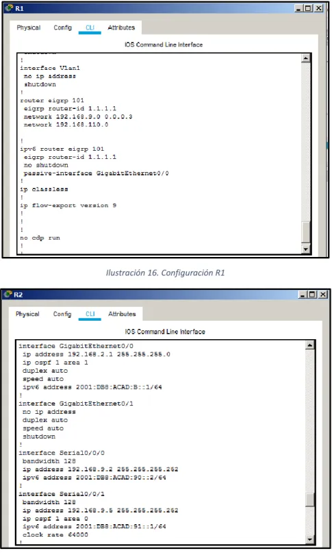
Ilustración 15. Configuración R1
Ilustración 16. Configuración R1
28
Ilustración 18. Configuración R2
29
Ilustración 20. Configuración R3
30
2. ESCENARIO 2
Una empresa de comunicaciones presenta una estructura Core acorde a la topología de red, en donde el estudiante será el administrador de la red, el cual deberá configurar e interconectar entre sí cada uno de los dispositivos que forman parte del escenario, acorde con los lineamientos establecidos para el direccionamiento IP, etherchannels, VLANs y demás aspectos que forman parte del escenario propuesto.
Topología de red
Ilustración 21. Escenario 2 Topología de red
Parte 1: Configurar la red de acuerdo con las especificaciones a. Apagar todas las interfaces en cada switch.
Solución
Configuración DLS1
Switch(config)#hostname DLS1
DLS1(config)#interface range G1/0/1-24 DLS1(config-if-range)#shutdown
Configuración DLS2
Switch(config)#hostname DLS2
31 Configuración ALS1
Switch(config)#hostname ALS1
ALS1(config)#interface range fa0/1-24 ALS1(config-if-range)#shutdown
Configuración ALS2
Switch(config)#hostname ALS2
ALS2(config)#interface range Fa0/1-24 ALS2(config-if-range)#shutdown
b. Asignar un nombre a cada switch acorde al escenario establecido. Solución
Configuración DLS1
Switch(config)#hostname DLS1
Configuración DLS2
Switch(config)#hostname DLS2
Configuración ALS1
Switch(config)#hostname ALS1
Configuración ALS2
Switch(config)#hostname ALS2
c. Configurar los puertos troncales y Port-channels tal como se muestra en el diagrama.
1) La conexión entre DLS1 y DLS2 será un Etherchannel capa-3 utilizando LACP. Para DLS1 se utilizará la dirección IP 10.12.12.1/30 y para DLS2 utilizará 10.12.12.2/30.
Solución
Configuración DLS1
DLS1(config)#interface range G1/0/11-12 DLS1(config-if-range)#no shutdown
32
%LINK-5-CHANGED: Interface GigabitEthernet1/0/12, changed state to down DLS1(config-if-range)#no switchport
DLS1(config-if-range)#channel-group 12 mode active DLS1(config-if-range)#
Creating a port-channel interface Port-channel 12
DLS1(config-if-range)#ex
DLS1(config)#interface port-channel 12
DLS1(config-if)#ip address 10.12.12.1 255.255.255.252 DLS1(config-if)#no shutdown
DLS1(config-if)#ex
Configuración DLS2
DLS2(config)#interface range G1/0/11-12 DLS2(config-if-range)#no switchport
DLS2(config-if-range)#channel-group 12 mode active DLS2(config-if-range)#
Creating a port-channel interface Port-channel 12
DLS2(config-if-range)#no shutdown
DLS2(config-if-range)#
%LINK-5-CHANGED: Interface GigabitEthernet1/0/11, changed state to up
%LINEPROTO-5-UPDOWN: Line protocol on Interface GigabitEthernet1/0/11, changed state to up
%LINK-5-CHANGED: Interface GigabitEthernet1/0/12, changed state to up
%LINEPROTO-5-UPDOWN: Line protocol on Interface GigabitEthernet1/0/12, changed state to up
%LINK-5-CHANGED: Interface Port-channel12, changed state to up
%LINEPROTO-5-UPDOWN: Line protocol on Interface Port-channel12, changed state to up
DLS2(config-if-range)#ex
DLS2(config)#interface port-channel 12
33
2) Los Port-channels en las interfaces Fa0/7 y Fa0/8 utilizarán LACP. Solución
Configuración DLS1
DLS1(config)#int range g1/0/7-8 DLS1(config-if-range)#no shut
%LINK-5-CHANGED: Interface GigabitEthernet1/0/7, changed state to down
%LINK-5-CHANGED: Interface GigabitEthernet1/0/8, changed state to down DLS1(config-if-range)#no switchport
DLS1(config-if-range)#channel-group 1 mode active DLS1(config-if-range)#
Creating a port-channel interface Port-channel 1
DLS1(config-if-range)#ex
Configuración ALS1
ALS1(config)#interface range fa0/7-8 ALS1(config-if-range)#no shutdown ALS1(config-if-range)#
%LINK-5-CHANGED: Interface FastEthernet0/7, changed state to up
%LINEPROTO-5-UPDOWN: Line protocol on Interface FastEthernet0/7, changed state to up
%LINK-5-CHANGED: Interface FastEthernet0/8, changed state to up
%LINEPROTO-5-UPDOWN: Line protocol on Interface FastEthernet0/8, changed state to up
ALS1(config-if-range)#switchport trunk encapsulation dot1q ^
% Invalid input detected at '^' marker.
ALS1(config-if-range)#switchport mode trunk
ALS1(config-if-range)#
34
%LINEPROTO-5-UPDOWN: Line protocol on Interface FastEthernet0/7, changed state to up
%LINEPROTO-5-UPDOWN: Line protocol on Interface FastEthernet0/8, changed state to down
%LINEPROTO-5-UPDOWN: Line protocol on Interface FastEthernet0/8, changed state to up
ALS1(config-if-range)#channel-group 1 mode active ALS1(config-if-range)#
Creating a port-channel interface Port-channel 1
%LINEPROTO-5-UPDOWN: Line protocol on Interface FastEthernet0/7, changed state to down
%LINEPROTO-5-UPDOWN: Line protocol on Interface FastEthernet0/7, changed state to up
%LINEPROTO-5-UPDOWN: Line protocol on Interface FastEthernet0/8, changed state to down
%LINEPROTO-5-UPDOWN: Line protocol on Interface FastEthernet0/8, changed state to up
ALS1(config-if-range)#ex
Configuración DLS2
DLS2(config)#interface range g1/0/7-8 DLS2(config-if-range)#no shutdown
%LINK-5-CHANGED: Interface GigabitEthernet1/0/7, changed state to down
%LINK-5-CHANGED: Interface GigabitEthernet1/0/8, changed state to down DLS2(config-if-range)#no switchport
DLS2(config-if-range)#channel-group 2 mode active DLS2(config-if-range)#
Creating a port-channel interface Port-channel 2
DLS2(config-if-range)#ex
35 ALS2(config)#interface range fa0/7-8 ALS2(config-if-range)#no shutdown
ALS2(config-if-range)#
%LINK-5-CHANGED: Interface FastEthernet0/7, changed state to up
%LINEPROTO-5-UPDOWN: Line protocol on Interface FastEthernet0/7, changed state to up
%LINK-5-CHANGED: Interface FastEthernet0/8, changed state to up
%LINEPROTO-5-UPDOWN: Line protocol on Interface FastEthernet0/8, changed state to up
ALS2(config-if-range)#switchport trunk encapsulation dot1q ^
% Invalid input detected at '^' marker.
ALS2(config-if-range)#switchport mode trunk
ALS2(config-if-range)#
%LINEPROTO-5-UPDOWN: Line protocol on Interface FastEthernet0/7, changed state to down
%LINEPROTO-5-UPDOWN: Line protocol on Interface FastEthernet0/7, changed state to up
%LINEPROTO-5-UPDOWN: Line protocol on Interface FastEthernet0/8, changed state to down
%LINEPROTO-5-UPDOWN: Line protocol on Interface FastEthernet0/8, changed state to up
ALS2(config-if-range)#channel-group 2 mode active ALS2(config-if-range)#
Creating a port-channel interface Port-channel 2
%LINEPROTO-5-UPDOWN: Line protocol on Interface FastEthernet0/7, changed state to down
36
%LINEPROTO-5-UPDOWN: Line protocol on Interface FastEthernet0/8, changed state to down
%LINEPROTO-5-UPDOWN: Line protocol on Interface FastEthernet0/8, changed state to up
3) Los Port-channels en las interfaces F0/9 y fa0/10 utilizará PAgP. Solución
Configuración DLS1
DLS1(config)#interface range g1/0/9-10 DLS1(config-if-range)#no switchport DLS1(config-if-range)#no shutdown
%LINK-5-CHANGED: Interface GigabitEthernet1/0/9, changed state to down
%LINK-5-CHANGED: Interface GigabitEthernet1/0/10, changed state to down DLS1(config-if-range)#channel-group 4 mode desirable
DLS1(config-if-range)#
Creating a port-channel interface Port-channel 4
DLS1(config-if-range)#ex
Configuración ALS1
ALS1(config)#interface range fa0/9-10 ALS1(config-if-range)#no switchport % Incomplete command.
ALS1(config-if-range)#switchport trunk encapsulation dot1q ^
% Invalid input detected at '^' marker.
ALS1(config-if-range)#switchport mode trunk
ALS1(config-if-range)#channel-group 3 mode desirable ALS1(config-if-range)#
Creating a port-channel interface Port-channel 3
ALS1(config-if-range)#no shut ALS1(config-if-range)#
%LINK-5-CHANGED: Interface FastEthernet0/9, changed state to up
%LINEPROTO-5-UPDOWN: Line protocol on Interface FastEthernet0/9, changed state to up
37
%LINEPROTO-5-UPDOWN: Line protocol on Interface FastEthernet0/10, changed state to up
ALS1(config-if-range)#ex
Configuración DLS2
DLS2(config)#interface range g1/0/9-10 DLS2(config-if-range)#no switchport DLS2(config-if-range)#no shutdown
%LINK-5-CHANGED: Interface GigabitEthernet1/0/9, changed state to down DLS2(config-if-range)#channel-group 3 mode desirable
DLS2(config-if-range)#
Creating a port-channel interface Port-channel 3
DLS2(config-if-range)#ex
Configuración ALS2
ALS2(config)#interface range fa0/9-10
ALS2(config-if-range)#switchport mode trunk
ALS2(config-if-range)#channel-group 4 mode desirable ALS2(config-if-range)#
Creating a port-channel interface Port-channel 4
ALS2(config-if-range)#no shutdown ALS2(config-if-range)#
%LINK-5-CHANGED: Interface FastEthernet0/9, changed state to up
%LINEPROTO-5-UPDOWN: Line protocol on Interface FastEthernet0/9, changed state to up
%LINK-5-CHANGED: Interface FastEthernet0/10, changed state to up
%LINEPROTO-5-UPDOWN: Line protocol on Interface FastEthernet0/10, changed state to up
ALS2(config-if-range)#
38 Solución
Configuración DLS1
DLS1(config)#interface Po1
DLS1(config-if)#switchport trunk native vlan 800 DLS1(config-if)#exit
DLS1(config)#interface Po4
DLS1(config-if)#switchport trunk native vlan 800 DLS1(config-if)#exit
Configuración DLS2
DLS2(config)#interface Po2
DLS2(config-if)#switchport trunk native vlan 800 DLS2(config-if)#exit
DLS2(config)#interface Po3
DLS2(config-if)#switchport trunk native vlan 800 DLS2(config-if)#exit
Configuración ALS1
ALS1(config)#interface Po1
ALS1(config-if)#switchport trunk native vlan 800 ALS1(config-if)#exit
ALS1(config)#interface Po3
ALS1(config-if)#switchport trunk native vlan 800 ALS1(config-if)#exit
Configuración ALS2
ALS2(config)#interface Po2
ALS2(config-if)#switchport trunk native vlan 800 ALS2(config-if)#exit
ALS2(config)#interface Po4
ALS2(config-if)#switchport trunk native vlan 800 ALS2(config-if)#exit
d. Configurar DLS1, ALS1, y ALS2 para utilizar VTP versión 3. 1) Utilizar el nombre de dominio UNAD con la contraseña cisco123
Solución
Configuración DLS1
DLS1(config)#vtp domain UNAD
Changing VTP domain name from NULL to UNAD DLS1(config)#vtp password cisco123
39 DLS1(config)#vtp version 3
^
% Invalid input detected at '^' marker.
Configuración ALS1
ALS1(config)#vtp domain UNAD
Changing VTP domain name from NULL to UNAD ALS1(config)#vtp password cisco123
Setting device VLAN database password to cisco123 ALS1(config)#vtp version 3
^
% Invalid input detected at '^' marker.
Configuración ALS2
ALS2(config)#vtp domain UNAD
Changing VTP domain name from NULL to UNAD ALS2(config)#vtp password cisco123
Setting device VLAN database password to cisco123 ALS2(config)#vtp version 3
^
% Invalid input detected at '^' marker.
2) Configurar DLS1 como servidor principal para las VLAN. Solución
Configuración DLS1
DLS1(config)#vtp mode server Device mode already VTP SERVER.
3) Configurar ALS1 y ALS2 como clientes VTP. Solución
Configuración ALS1
ALS1(config)#vtp mode client
Setting device to VTP CLIENT mode.
40 ALS2(config)#vtp mode client
Setting device to VTP CLIENT mode.
e. Configurar en el servidor principal las siguientes VLAN:
Tabla 1. VLAN
Solución
Configuración DLS1
DLS1(config)#vlan 800
DLS1(config-vlan)#name NATIVA DLS1(config-vlan)#vlan 12
DLS1(config-vlan)#name EJECUTIVOS DLS1(config-vlan)#vlan 234
DLS1(config-vlan)#name HUESPEDES DLS1(config-vlan)#vlan 1111
VLAN_CREATE_FAIL: Failed to create VLANs 1111 : extended VLAN(s) not allowed in current VTP mode
DLS1(config)#vlan 111
DLS1(config-vlan)#name VIDEONET DLS1(config-vlan)#vlan 434
DLS1(config-vlan)#name ESTACIONAMIENTO DLS1(config-vlan)#vlan 123
DLS1(config-vlan)#name MANTENIMIENTO DLS1(config-vlan)#vlan 1010
VLAN_CREATE_FAIL: Failed to create VLANs 1010 : extended VLAN(s) not allowed in current VTP mode
DLS1(config)#vlan 101
DLS1(config-vlan)#name VOZ DLS1(config-vlan)#vlan 345
DLS1(config-vlan)#name ADMINISTRACION
41 Solución Configuración DLS1 DLS1(config)#vlan 434 DLS1(config-vlan)#name ESTACIONAMIENTO DLS1(config-vlan)#state suspend ^
% Invalid input detected at '^' marker.
g. Configurar DLS2 en modo VTP transparente VTP utilizando VTP versión 2, y configurar en DLS2 las mismas VLAN que en DLS1.
Solución
DLS2(config)#vtp mode transparent
Setting device to VTP TRANSPARENT mode. DLS2(config)#vtp version 2
DLS2(config)#vlan 800 DLS2(config-vlan)#name NATIVA DLS2(config-vlan)#vlan 12 DLS2(config-vlan)#name EJECUTIVOS DLS2(config-vlan)#vlan 234 DLS2(config-vlan)#name HUESPEDES DLS2(config-vlan)#vlan 111 DLS2(config-vlan)#name VIDEONET DLS2(config-vlan)#vlan 434 DLS2(config-vlan)#name ESTACIONAMIENTO DLS2(config-vlan)#vlan 123 DLS2(config-vlan)#name MANTENIMIENTO DLS2(config-vlan)#vlan 101 DLS2(config-vlan)#name VOZ DLS2(config-vlan)#vlan 345 DLS2(config-vlan)#name ADMINISTRACION DLS2(config-vlan)#exit
h. Suspender VLAN 434 en DLS2. Solución
DLS2(config)#vlan 434
DLS2(config-vlan)#state suspend ^
% Invalid input detected at '^' marker.
42 Solución
DLS2(config)#vlan 567
DLS2(config-vlan)#name CONTABILIDAD DLS2(config-vlan)#ex
DLS2(config)#interface port-channel 2
DLS2(config-if)#switchport trunk allowed vlan except 567 DLS2(config-if)#exit
DLS2(config)#interface port-channel 3
DLS2(config-if)#switchport trunk allowed vlan except 567
j. Configurar DLS1 como Spanning tree root para las VLAN 1, 12, 434, 800, 1010, 1111 y 3456 y como raíz secundaria para las VLAN 123 y 234.
Solución
DLS1(config)#spanning-tree vlan 1,12,434,800,101,111,345 root primary DLS1(config)#spanning-tree vlan 123,234 root secondary
k. Configurar DLS2 como Spanning tree root para las VLAN 123 y 234 y como una raíz secundaria para las VLAN 12, 434, 800, 1010, 1111 y 3456.
Solución
DLS2(config)#spanning-tree vlan 123,234 root primary
DLS2(config)#spanning-tree vlan 12,434,800,101,111,345 root secondary
l. Configurar todos los puertos como troncales de tal forma que solamente las VLAN que se han creado se les permitirá circular a través de éstos puertos.
Solución
m. Configurar las siguientes interfaces como puertos de acceso, asignados a las VLAN de la siguiente manera:
Tabla 2. Configuración de interfaces
Solución
Configuración DLS1
DLS1(config)#interface g1/0/6
43 DLS1(config-if)#switchport access vlan 345 DLS1(config-if)#spanning-tree portfast
%Warning: portfast should only be enabled on ports connected to a single host. Connecting hubs, concentrators, switches, bridges, etc... to this interface when portfast is enabled, can cause temporary bridging loops. Use with CAUTION
%Portfast has been configured on GigabitEthernet1/0/6 but will only have effect when the interface is in a non-trunking mode.
DLS1(config-if)#no shutdown
DLS1(config-if)#
%LINK-5-CHANGED: Interface GigabitEthernet1/0/6, changed state to up
%LINEPROTO-5-UPDOWN: Line protocol on Interface GigabitEthernet1/0/6, changed state to up
Configuración DLS2
DLS2(config)#interface g1/0/6
DLS2(config-if)#switchport mode access DLS2(config-if)#switchport access vlan 345 DLS2(config-if)#spanning-tree portfast
%Warning: portfast should only be enabled on ports connected to a single host. Connecting hubs, concentrators, switches, bridges, etc... to this interface when portfast is enabled, can cause temporary bridging loops. Use with CAUTION
%Portfast has been configured on GigabitEthernet1/0/6 but will only have effect when the interface is in a non-trunking mode.
DLS2(config-if)#no shutdown
DLS2(config-if)#
%LINK-5-CHANGED: Interface GigabitEthernet1/0/6, changed state to up
%LINEPROTO-5-UPDOWN: Line protocol on Interface GigabitEthernet1/0/6, changed state to up
Configuración ALS1
ALS1(config)#interface fa0/6
ALS1(config-if)#switchport mode access
44 ALS1(config-if)#spanning-tree portfast
%Warning: portfast should only be enabled on ports connected to a single host. Connecting hubs, concentrators, switches, bridges, etc... to this interface when portfast is enabled, can cause temporary bridging loops. Use with CAUTION
%Portfast has been configured on FastEthernet0/6 but will only have effect when the interface is in a non-trunking mode. ALS1(config-if)#no shutdown
Configuración ALS2
ALS2(config)#interface fa0/6
ALS2(config-if)#switchport mode access ALS2(config-if)#switchport access vlan 234 ALS2(config-if)#spanning-tree portfast
%Warning: portfast should only be enabled on ports connected to a single host. Connecting hubs, concentrators, switches, bridges, etc... to this interface when portfast is enabled, can cause temporary bridging loops. Use with CAUTION
%Portfast has been configured on FastEthernet0/6 but will only have effect when the interface is in a non-trunking mode. ALS2(config-if)#no shutdown
ALS2(config-if)#
%LINK-5-CHANGED: Interface FastEthernet0/6, changed state to up
%LINEPROTO-5-UPDOWN: Line protocol on Interface FastEthernet0/6, changed state to up
Parte 2: conectividad de red de prueba y las opciones configuradas.
a. Verificar la existencia de las VLAN correctas en todos los switches y la asignación de puertos troncales y de acceso.
45
Ilustración 22. Verificación de VLANs en DSL1
Ilustración 23. Verificación de VLANs en DSL2
b. Verificar que el Etherchannel entre DLS1 y ALS1 está configurado correctamente.
46
Ilustración 24. Verificación de Etherchannel en DSL1
Ilustración 25. Verificación de Etherchannel en DSL1
47
3. CONCLUSIONES
El estudiante ha elaborado en este documento en el cual se desarrolla la prueba de habilidades del diplomado de cisco CCNP, cumpliendo con las normas ICONTEC NTC1486 y los lineamientos establecidos en la previa guía de la actividad.
En telecomunicaciones son conocidos una gran variedad de protocolos de
enrutamiento de capa 3 para interconectar países, empresas, personas, entre
otras. En el escenario 1, con la configuración de los protocolos EIGRP y OSPF, en cada uno de los routers, adicional, a los parámetros de configuración de los protocolos, es necesario, configurar en el router central la redistribución para la comunicación de las sucursales de la empresa de confecciones que se encuentran distribuidas en diferentes ciudades.
En la capa 2 del modelo OSI, no es excepción de establecer protocolos en los dispositivos, que generalmente en la actualidad son utilizados en los equipos switch capa 2. Dentro de las configuraciones lógicas realizadas en los dispositivos, se crearon VLANS para cada una de las áreas que hacen parte de la empresa, con el fin de que solo los equipos de los empleados de cada área tengan comunicación entre sí.
48
BIBLIOGRAFÍA
Cisco Packet Tracer. Ecured. Recuperado el 26 de Febrero de 2020 de
https://www.ecured.cu/Cisco_Packet_Tracer
GNS3. Universidad Complutense Madrid. Recuperado el 26 de Febrero de 2020
de https://www.ucm.es/pimcd2014-free-software/gns3
Ipv4. Ecured. Recuperado el 26 de Febrero de 2020 de https://www.ecured.cu/Ipv4
Protocolos de Red. Ecured. Recuperado el 26 de Febrero de 2020 de
https://www.ecured.cu/Protocolos_de_red
Router - conectividad de redes. Centro de innovacion y soluciones empresariales
tecnologicas. Recuperado el 26 de Febrero de 2020 de
https://www.ciset.es/glosario/474-router
Untiveros, S. (s.f.). Que es el switch? Aprenda Redes. Recuperado el 26 de
Febrero de 2020 de
https://www.aprendaredes.com/dev/articulos/que-es-el-switch.htm
Walton, A. (s.f.). Segmentacion de VLAN: Introducción. CCNA desde Cero.
Recuperado el 26 de Febrero de 2020 de
49 ANEXOS