Prueba de Habilidades Prácticas CCNA
Presentado por:
Yoimir Yamit Castrillon Duque Código 1099547401
Presentado a: Nancy Guaca
Universidad Nacional Abierta y a Distancia - UNAD Escuela De Ciencias Básicas Tecnología e Ingeniería - ECBTI
Introducción
En la presente actividad se plantean la aplicación de los conocimientos teóricos y prácticos adquiridos, asimilados y abordados en el curso de profundización CCNA uno y dos.
Dicho proceso se centra en dos escenarios, con diferentes depósitos, como router, switchs, computadores de escritorio, computadores de escritorio, vlans, en topologías y situaciones de la vida real, con reglas de NAT y reglas de filtro de información.
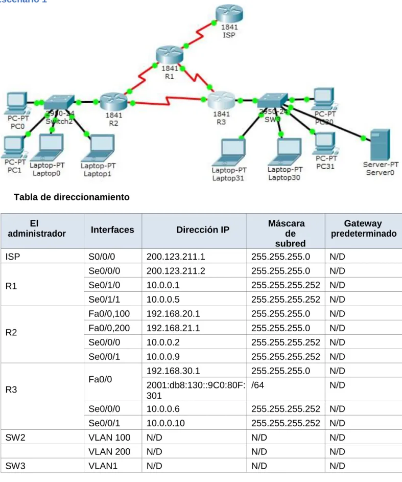
Escenario 1
Tabla de direccionamiento
El
administrador Interfaces Dirección IP
Máscara de subred
Gateway predeterminado
ISP S0/0/0 200.123.211.1 255.255.255.0 N/D
R1
Se0/0/0 200.123.211.2 255.255.255.0 N/D
Se0/1/0 10.0.0.1 255.255.255.252 N/D
Se0/1/1 10.0.0.5 255.255.255.252 N/D
R2
Fa0/0,100 192.168.20.1 255.255.255.0 N/D
Fa0/0,200 192.168.21.1 255.255.255.0 N/D
Se0/0/0 10.0.0.2 255.255.255.252 N/D
Se0/0/1 10.0.0.9 255.255.255.252 N/D
R3
Fa0/0 192.168.30.1 255.255.255.0 N/D
2001:db8:130::9C0:80F: 301
/64 N/D
Se0/0/0 10.0.0.6 255.255.255.252 N/D
Se0/0/1 10.0.0.10 255.255.255.252 N/D
SW2 VLAN 100 N/D N/D N/D
VLAN 200 N/D N/D N/D
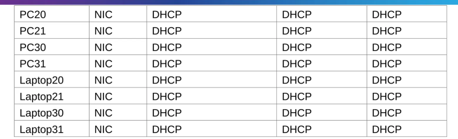
PC20 NIC DHCP DHCP DHCP
PC21 NIC DHCP DHCP DHCP
PC30 NIC DHCP DHCP DHCP
PC31 NIC DHCP DHCP DHCP
Laptop20 NIC DHCP DHCP DHCP
Laptop21 NIC DHCP DHCP DHCP
Laptop30 NIC DHCP DHCP DHCP
Laptop31 NIC DHCP DHCP DHCP
Tabla de asignación de VLAN y de puertos
Dispositiv o
VLAN Nombre Interfa
z
SW2 100 LAPTOPS Fa0/2-3
SW2 200 DESTOPS Fa0/4-5
SW3 1 - Todas las interfaces
Tabla de enlaces troncales
Dispositivo local
Interfaz local
Dispositivo remoto
SW2 Fa0/2-3 100
Situación
En esta actividad, demostrará y reforzará su capacidad para implementar NAT, servidor de DHCP, RIPV2 y el routing entre VLAN, incluida la configuración de direcciones IP, las VLAN, los enlaces troncales y las subinterfaces. Todas las pruebas de alcance deben realizarse a través de ping únicamente.
Descripción de las actividades
Switch 2
Switch>enable Switch#configure t
Enter configuration commands, one per line. End with CNTL/Z. SW2(config)#vlan 100 SW2(config-vlan)#name LAPTOPS SW2(config-vlan)#EXIT SW2(config)#vlan 200 SW2(config-vlan)#name DESTOPS SW2(config-vlan)#EXIT SW2(config)#exit SW2#
%SYS-5-CONFIG_I: Configured from console by console
SW2#copy running-config startup-config Destination filename [startup-config]? Building configuration...
[OK]
SW2#enable
SW2#configure terminal
Enter configuration commands, one per line. End with CNTL/Z. SW2(config)#
SW2#
%SYS-5-CONFIG_I: Configured from console by console SW2#enable
SW2#configure terminal
Enter configuration commands, one per line. End with CNTL/Z. SW2(config)#int range f0/2-3
SW2(config-if-range)#switchport mode access SW2(config-if-range)#switchport access vlan 100 SW2(config-if-range)#exit
SW2(config)#int range f0/4-5
SW2(config-if-range)#switchport mode access SW2(config-if-range)#switchport access vlan 200 SW2(config-if-range)#exit
SW2#copy running-config startup-config
Interfaz int fa0/1
SW2(config)#int fa0/1
SW2(config-if)#switchport mode trunk SW2(config-if)#exit
SW2(config)#exit SW2#
Switch#configure t
Enter configuration commands, one per line. End with CNTL/Z. Switch(config)#hostname SW3
SW3(config)#vlan 1
SW3(config-vlan)#int range f0/1-24
SW3(config-if-range)#switchport mode access SW3(config-if-range)#switchport access vlan 1 SW3(config-if-range)#exit
SW3(config)#exit SW3#
%SYS-5-CONFIG_I: Configured from console by console
SW3#copy running-config startup-config Destination filename [startup-config]? Building configuration...
[OK] SW3#
Los puertos de red que no se utilizan se deben deshabilitar.
SW3#
SW3#enable SW3#configure t
Enter configuration commands, one per line. End with CNTL/Z. SW3(config)#int range fa0/6-23
SW3(config-if-range)#shutdown
%LINK-5-CHANGED: Interface FastEthernet0/7, changed state to administratively down %LINK-5-CHANGED: Interface FastEthernet0/8, changed state to administratively down %LINK-5-CHANGED: Interface FastEthernet0/9, changed state to administratively down %LINK-5-CHANGED: Interface FastEthernet0/10, changed state to administratively down %LINK-5-CHANGED: Interface FastEthernet0/11, changed state to administratively down %LINK-5-CHANGED: Interface FastEthernet0/12, changed state to administratively down %LINK-5-CHANGED: Interface FastEthernet0/13, changed state to administratively down %LINK-5-CHANGED: Interface FastEthernet0/14, changed state to administratively down %LINK-5-CHANGED: Interface FastEthernet0/15, changed state to administratively down %LINK-5-CHANGED: Interface FastEthernet0/16, changed state to administratively down %LINK-5-CHANGED: Interface FastEthernet0/17, changed state to administratively down %LINK-5-CHANGED: Interface FastEthernet0/18, changed state to administratively down %LINK-5-CHANGED: Interface FastEthernet0/19, changed state to administratively down %LINK-5-CHANGED: Interface FastEthernet0/20, changed state to administratively down %LINK-5-CHANGED: Interface FastEthernet0/21, changed state to administratively down %LINK-5-CHANGED: Interface FastEthernet0/22, changed state to administratively down %LINK-5-CHANGED: Interface FastEthernet0/23, changed state to administratively down SW3(config-if-range)#
%LINK-5-CHANGED: Interface FastEthernet0/6, changed state to administratively down
SW3(config-if-range)#exit SW3(config)#exit
SW3#
%SYS-5-CONFIG_I: Configured from console by console SW3#copy running-config startup-config
Destination filename [startup-config]? Building configuration...
[OK]
2. La información de dirección IP R1, R2 y R3 debe cumplir con la tabla 1.
R1
Router>enable Router#configure t
Enter configuration commands, one per line. End with CNTL/Z. Router(config)#hotsname R1
R1(config)#int se0/0/0
R1(config-if)#ip address 10.0.0.2 255.255.255.252 R1(config)#int Se0/1/0
R1(config-if)#ip address 10.0.0.1 255.255.255.252 R1(config-if)#int Se0/1/1
R1(config-if)#ip address 10.0.0.5 255.255.255.252 R1(config-if)#exit
R1(config)#exit R1#
%SYS-5-CONFIG_I: Configured from console by console
R1#copy running-config startup-config Destination filename [startup-config]? Building configuration...
[OK] R1# R2
R2>enable R2#configure t
Enter configuration commands, one per line. End with CNTL/Z.
R2(config)#int fa0/0.100
R2(config-subif)#encapsulation dot1Q 100
R2(config-subif)#ip address 192.168.20.1 255.255.255.0 R2(config-subif)#exit
R2(config)#int fa0/0.200
R2(config-subif)#encapsulation dot1Q 200
R2(config-subif)#ip address 192.168.21.1 255.255.255.0 R2(config-subif)#exit
R2(config-if)#int se0/0/0
R2(config-if)#ip address 10.0.0.2 255.255.255.252 R2(config-if)#no shutdown
R2(config-if)#int se0/0/1
R2(config-if)#ip address 10.0.0.9 255.255.255.252 R2(config-if)#no shutdown
R2(config)#exit
Configuración R3
R3>enable
R3#configure terminal
Enter configuration commands, one per line. End with CNTL/Z. R3(config-if)#int se0/0/0
R3(config-if)#ip address 10.0.0.6 255.255.255.252 R3(config-if)#int se0/0/1
R3(config-if)#ip address 10.0.0.10 255.255.255.252 R3(config-if)#exit
R3(config)#interface FastEthernet0/0
R3 (config-if)# ip address 192.168.30.1 255.255.255.0 R3 (config-if)#ipv6 address 2001:db8:130::9c0:80f:301/64 R3(config-if)#no shutdown
R3 (config-if)#exit R3(config)#exit
R3%SYS-5-CONFIG_I: Configured from console by console Router#copy running-config startup-config
Destination filename [startup-config]? Building configuration...
[OK] Router
Configuración de ROUTER ISP
Router>enable Router#configure t
Enter configuration commands, one per line. End with CNTL/Z. Router(config)#hostname ISP
ISP(config)#int S0/0/0
ISP(config-if)#ip address 200.123.211.1 255.255.255.0 ISP(config-if)#no shutdown
ISP(config-if)#exit
ISP#copy running-config startup-config Destination filename [startup-config]? Building configuration...
[OK] ISP#
4. R1 debe realizar una NAT con sobrecarga sobre una dirección IPv4 pública. Asegúrese de que todos los terminales pueden comunicarse con Internet pública (haga ping a la dirección ISP) y la lista de acceso estándar se llama INSIDE-DEVS.
R1 con NAT con sobrecarga
R1#enable
R1#configure terminal
Enter configuration commands, one per line. End with CNTL/Z. R1(config)#int s0/1/1
R1(config-if)#ip nat inside R1(config-if)#exit
R1(config)#int s0/1/0
R1(config-if)#ip nat inside R1(config-if)#exit
R1(config)#int s0/0/0
R1(config-if)#ip nat outside
R1(config)#access-list 1 permit 10.0.0.0 0.255.255.255
R1(config)#ip nat inside source list 1 interface s0/0/0 overload
R1(config)#ip nat inside source static tcp 192.168.30.6 80 200.123.211.1 80 R1(config)#route rip R1(config-router)#version 2 R1(config-router)#network 10.0.0.0 R1(config-router)#exit R1(config)#exit R1#
%SYS-5-CONFIG_I: Configured from console by console R1#wr
Building configuration... [OK]
R1# R1#
R1#show ip nat translation
Pro Inside global Inside local Outside local Outside global tcp 200.123.211.1:80 192.168.30.6:80
1#show ip nat statistics
Total translations: 1 (1 static, 0 dynamic, 1 extended) Outside Interfaces: Serial0/0/0
Inside Interfaces: Serial0/1/0 , Serial0/1/1 Hits: 0 Misses: 0
Expired translations: 0 Dynamic mappings: R1#
5. R1 debe tener una ruta estática predeterminada al ISP que se configuró y que
incluye esa ruta en el dominio RIPv2.
R1>show ip nat statistics
Total translations: 1 (1 static, 0 dynamic, 1 extended) Outside Interfaces: Serial0/0/0
Inside Interfaces: Serial0/1/0 , Serial0/1/1 Hits: 0 Misses: 0
Expired translations: 0 Dynamic mappings: R1>
6. R2 es un servidor de DHCP para los dispositivos conectados al puerto FastEthernet0/0.
R2>enable R2#configure t
Enter configuration commands, one per line. End with CNTL/Z. R2(config)#ip dhcp excluded-address 10.0.0.2 10.0.0.9
R2(dhcp-config)#NETwork 192.168.20.1 255.255.255.0 R2(dhcp-config)#NETwork 192.168.21.1
R2#
%SYS-5-CONFIG_I: Configured from console by console R2#configure t
Enter configuration commands, one per line. End with CNTL/Z. R2(config)#ip dhcp excluded-address 10.0.0.2 10.0.0.9
R2(config)#ip dhcp pool INSIDE-DEVS
R2(dhcp-config)#NETwork 192.168.20.1 255.255.255.0 R2(dhcp-config)#NETwork 192.168.21.1 255.255.255.0 R2(dhcp-config)#default-router 192.168.1.1
R2(dhcp-config)#dns-server 0.0.0.0 R2(dhcp-config)#exit
R2(config)#exit R2#
%SYS-5-CONFIG_I: Configured from console by console wr
Building configuration... [OK]
R2#
9. El Servidor0 es sólo un servidor IPv6 y solo debe ser accesibles para los dispositivos en R3 (ping).
12. R1, R2 y R3 intercambian información de routing mediante RIP versión 2.
Configuración RIV 2
R1>enable R1#configure t
Enter configuration commands, one per line. End with CNTL/Z. R1(config)#route rip
R1(config-router)#version 2
R1(config-router)#do show ip route connected C 10.0.0.0/30 is directly connected, Serial0/1/0 C 10.0.0.4/30 is directly connected, Serial0/1/1 R1(config-router)#network 10.0.0.0
R1(config-router)#network 10.0.0.4 R1(config-router)#exit
R1(config)#exit R1#
%SYS-5-CONFIG_I: Configured from console by console R1#wr Building configuration... [OK] R1# R2>enable R2#configure t
Enter configuration commands, one per line. End with CNTL/Z. R2(config)#route rip
R2(config-router)#version 2
R2(config-router)#do show ip route connected C 10.0.0.0/30 is directly connected, Serial0/0/0 C 10.0.0.8/30 is directly connected, Serial0/0/1 R2(config-router)#network 10.0.0.0
R2(config-router)#network 10.0.0.8 R2(config-router)#exit
R2(config)#exit R2#
%SYS-5-CONFIG_I: Configured from console by console R2#wr
Building configuration..
R3>enable R3#configure t
Enter configuration commands, one per line. End with CNTL/Z. R3(config)#route rip
R3(config-router)#version 2
C 10.0.0.4/30 is directly connected, Serial0/0/0 C 10.0.0.8/30 is directly connected, Serial0/0/1
C 192.168.30.0/24 is directly connected, FastEthernet0/0 R3(config-router)#network 10.0.0.0
R3(config-router)#network 10.0.0.8 R3(config-router)#exit
R3(config)#exit R3#
Escenario 2
Escenario: Una empresa de Tecnología posee tres sucursales distribuidas en las ciudades de Miami, Bogotá y Buenos Aires, en donde el estudiante será el administrador de la red, el cual deberá configurar e interconectar entre sí cada uno de los dispositivos que forman parte del escenario, acorde con los lineamientos establecidos para el direccionamiento IP, protocolos de enrutamiento y demás aspectos que forman parte de la topología de red.
Router Bogotá: R1
enable
configure terminal hostname Bogota interface s0/0/0
ip address 172.31.21.1 255.255.255.252 clock rate 64000
no shutdown
Router Miami: R2
configure terminal hostname Miami interface loop0
ip address 10.10.10.10 255.255.255.255 no shutdown
interface s0/0/0
ip address 172.31.23.1 255.255.255.252 clock rate 64000
no shutdown interface s0/0/1
ip address 172.31.21.2 255.255.255.252 no shutdown
interface g0/0
ip address 209.165.200.225 255.255.255.248 no shutdown
Router Buenos Aires: R3
configure terminal hostname BuenosAires interface loop4
ip address 192.168.4.1 255.255.255.0 no shutdown
interface loop5
ip address 192.168.5.1 255.255.255.0 no shutdown
interface loop4
ip address 192.168.6.1 255.255.255.0 no shutdown
interface s0/0/1
2. Configurar el protocolo de enrutamiento OSPFv2 bajo los siguientes criterios:
OSPFv2 area 0
Configuration Item or Task Specification
Router ID R1 1.1.1.1
Router ID R2 5.5.5.5
Router ID R3 8.8.8.8
Configurar todas las interfaces LAN como pasivas
Establecer el ancho de banda para enlaces seriales en 256 Kb/s
Ajustar el costo en la métrica de S0/0 a 9500
R1
configure terminal router ospf 1 router-id 1.1.1.1
network 192.168.99.0 0.0.0.255 area 0 network 172.31.21.0 0.0.0.3 area 0 passive-interface gi0/0
interface s0/0/0 bandwidth 256 ip ospf cost 9500 interface s0/0/1 bandwidth 256
R2
configure terminal router ospf 1 router-id 5.5.5.5
network 209.165.200.224 0.0.0.7 area 0 network 172.31.21.0 0.0.0.3 area 0 network 10.10.10.10 0.0.0.3 area 0 passive-interface gi0/0
interface s0/0/0 bandwidth 256 ip ospf cost 9500 interface s0/0/1 bandwidth 256
R3
configure terminal router ospf 1 router-id 8.8.8.8
network 192.168.5.0 0.0.0.255 area 0 network 192.168.6.0 0.0.0.255 area 0 interface s0/0/0
bandwidth 256 ip ospf cost 9500 interface s0/0/1 bandwidth 256
3. Configurar VLANs, Puertos troncales, puertos de acceso, encapsulamiento, Inter-VLAN Routing y Seguridad en los Switches acorde a la topología de red establecida.
VLANs
Switch1(config)#vlan 30
Switch1(config-vlan)#name Administracion Switch1(config-vlan)#exit
Switch1(config)#vlan 40
Switch1(config-vlan)#name Mercadeo Switch1(config-vlan)#exit
Switch1(config)#vlan 200
Switch1(config-vlan)#name Mantenimiento Switch1(config-vlan)#exit
SEGURIDAD
Aplica para todos los Switch:
line console 0 pass cisco line vty 0 4 pass cisco
enable secret cisco
INTERFACES DE VLAN
S1(config)#interface range fa0/1 S1(config-if)#switchport mode access S1(config-if)#switchport access vlan 30 S1(config-if)#exit
ENCAPSULAR
S1(config)#interface g0/0 S1(config-if)#no shutdown S1(config-if)#exit
S1(config-if)# encapsulation dot1Q 30
S1(config-if)# ip address 192.168.30.1 255.255.255.0 S1(config)# interface g0/0.4
S1(config-if)# encapsulation dot1Q 40
S1(config-if)# ip address 192.168.40.1 255.255.255.0 Exit
4. En el Switch 3 deshabilitar DNS lookup
S3(config)# no ip domain-lookup
5. Asignar direcciones IP a los Switches acorde a los lineamientos.
S3(config)# interface vlan1
S3(config-if)# ip address 192.168.99.3 255.255.255.0 S3(config-if)# no shutdown
S1(config)# interface vlan1
S1(config-if)# ip address 192.168.99.2 255.255.255.0 S1(config-if)# no shutdown
6. Configurar R1 como servidor DHCP para las VLANs 30 y 40.
Bogota(config)#ip dhcp pool vlan30
Bogota(dhcp-config)#network 192.168.30.0 255.255.255.0 Bogota(dhcp-config)#default-router 192.168.30.1
Bogota(dhcp-config)#ip dhcp pool vlan40
Bogota(dhcp-config)#network 192.168.40.0 255.255.255.0 Bogota(dhcp-config)#default-router 192.168.40.1
7. Reservar las primeras 30 direcciones IP de las VLAN 30 y 40 para configuraciones estáticas.
Bogota(config)#ip dhcp excluded-address 192.168.30.1 192.168.30.30
Bogota(config)# ip dhcp excluded-address 192.168.40.1 192.168.40.30
Configurar DHCP pool para VLAN 30
Configurar DHCP pool para VLAN 40
Name: MERCADEO DNS-Server: 10.10.10.11 Domain-Name: ccna-unad.com Establecer default gateway.
ADMINISTRACION
Bogota(config)# ip dhcp pool ADMINISTRACION Bogota(dhcp-config)# dns-server 10.10.10.11
Bogota(dhcp-config)# domain-name ccna-unad.com (El PT genera un error al ejecutar este comando, pero es el indicado)
Bogota(dhcp-config)# default-router 192.168.30.1
Bogota(dhcp-config)# network 192.168.30.0 255.255.255.0
MERCADEO
Bogota(config)# ip dhcp pool MERCADEO Bogota(dhcp-config)# dns-server 10.10.10.11
Bogota(dhcp-config)# domain-name ccna-unad.com (El PT genera un error al ejecutar este comando, pero es el indicado)
Bogota(dhcp-config)# default-router 192.168.40.1
Bogota(dhcp-config)# network 192.168.40.0 255.255.255.0
8. Configurar NAT en R2 para permitir que los host puedan salir a internet
Miami(config)#interface GigabitEthernet0/0 Miami(config-if)#ip nat inside
Miami(config-if)#int s0/0/0 Miami(config-if)#ip nat outside Miami(cint s0/0/0int s0/0/1
Miami(p nat outsideip nat outside Miami(config-if)#exit
9. Configurar al menos dos listas de acceso de tipo estándar a su criterio en para restringir o permitir tráfico desde R1 o R3 hacia R2.
10. Configurar al menos dos listas de acceso de tipo extendido o nombradas a su criterio en para restringir o permitir tráfico desde R1 o R3 hacia R2.
Miami(config)#access-list 10 permit 192.168.30.0 0.0.0.0 Miami(config)#access-list 10 permit 192.168.40.0 0.0.0.0
Miami(config)#ip nat pool ADMINISTRACION 209.165.200.220 209.165.200.221 netmask 255.255.255.248 Miami(config)#ip nat inside source list 10 pool ADMINISTRACION
Conclusiones
- El curso CCNA 1 y 2 aporta los recursos necesarios desde el punto de vista teórico y práctico para entender el fascinante mundo de las redes de datos.
- Los dispositivos de la marca CISCO sin duda alguna brindan el mejor rendimiento, personalización, robustez y disponibilidad del sector de las telecomunicaciones.
- Las telecomunicaciones ya no son solo asunto del sector empresarial, ya hoy en día están presentes en el hogar, en la educación, en la cotidianidad.
- Los laboratorios asistidos y de autoevaluación son la mejor herramienta para aprender configurando y estudiando.
Referencias Bibliográficas
- CISCO. (2014). Introducción a redes conmutadas. Principios de Enrutamiento y Conmutación. Recuperado de:https://static-course
assets.s3.amazonaws.com/RSE50ES/module1/index.html#1.0.1.1
- CISCO. Ethernet. Fundamentos de Networking. Recuperado : https://static-courseassets.s3.amazonaws.com/ITN50ES/module2/index.html#5.0.1.1