A I R - T O - A I R S U R V E I L L A N C E F O R F U T U R E A T M S Y S T E M S
Juan A. Besada, David Martin, Guillermo Frontera, Gonzalo de Miguel, Ana Bernardos GPDS-CEDITEC, Universidad Politecnica de Madrid, Madrid, Spain
Abstract
This paper describes a prototype implementation of ADS-B in an air-to-air surveillance system. This air surveillance system was defined for an experimental project on future civilian air traffic management, which imposes new requirements over both air and ground surveillance systems. In this paper the relation between the different airborne and ground systems related to air surveillance is detailed, and the air surveillance and its algorithms are described. It is related with current ADS-B and TIS-B proposals, and defined as an extension of those systems. Finally, performance of the air surveillance is detailed, based on simulated scenarios, and some conclusions for future enhancements of ADS-B function are derived.
1 Introduction
The Automatic Dependent Surveillance-Broadcast [1] (ADS-B) is a key enabler for all future Air traffic management (ATM) proposals, as it allows for both ground and air surveillance. As the surveillance function is a prerequisite for separation assurance (airborne and in ground), and ground flight intent conformity checking, this is a critical technology for civilian air traffic control. It is foreseen that, in coordination with Wide Area Multilateration Systems and Mode S radar it will progressively phase out current Secondary Surveillance Sensors.
As not every aircraft will be equipped with ADS-B enabling avionics, a complementary service to provide ground surveillance results (from other sensors) to equipped aircraft. This is the Traffic information system-Broadcast (TIS-B) [2].
ADS and TIS-B are not new concepts, what will change in the future is the level of availability of this technology in the aircraft fleet, and the potential inclusion of new sources of information, or new means for its representation or retrieval. Air surveillance system must be seen as a key enabler for secure and predictable flight and traffic management.
In this paper we will study the potential extensions to such protocol, to address potential role changes of the ADS-B in relation with Trajectory-Based Operations (TBO), which is the new paradigm to be used in future ATM systems such as those being defined under SESAR or NEXTGEN [3,4] research programs. This new ATM paradigm, based on the implementation of high performance trajectory prediction and on trajectory contracts between aircraft and ground based control, demands high accuracy in the predicted tracks by surveillance function, and an extension of the current ADS-B information to include new fields allowing for trajectory prediction.
Future ATM systems will additionally allow for a certain degree of control decentralization, based on separation responsibility delegation to aircraft, using Airborne Separation Assurance Systems. In order to implement these new roles, accurate and robust air-to-air surveillance systems should be deployed.
The research described in this paper has been performed within ATLANTIDA, which is an Spanish project aiming to implement a completely automatic prototype of an future ATM system with Unmanned Aircraft Systems (UASs). The proposed air surveillance system has been implemented for INDRA S.A. within this project and is integrated in the ATLANTIDA avionics prototypes.
Of special interest within this project from an ATM point of view is the definition of a novel communication and information system, known as SWIM (System Wide Information Management). This concept, also present in SESAR and NEXTGEN, assumes all data interchange and information retrieval demands are covered based in a unique communication infrastructure allowing for interoperability of different ATM actors. ADS-B, within this project, has been implemented over a SWIM network, instead of reusing previous technology.
section 3 we will describe the relation of air surveillance system with other avionic systems, its key roles and requirements. In section 4, based on previous requirements, we will define the new data formats and protocols to be used. Then, section 5 will describe internal air surveillance system structure and algorithms. Finally, section 6 will include some performance evaluation of the system based on simulated data, and section 7 will draw some conclusions and describe future research lines.
2 Current ADS-B and TIS-B
Implementations
There are several competing technologies for ADS-B implementation. Next we are summarizing some of the most important points of those implementations, especially with regards to the information they may provide, and to the protocols related with this communication.
2.1 Mode S Squitter
This is currently the most used ADS-B implementation. In fact, both SESAR and NEXTGEN take an approach of concentrating efforts on this technology, which can be installed and updated with minor changes into currently mandatory Mode S transponders (for a great part of the aircraft fleet). It is also known as 1090 ES (1090 Extended Squitter).
We will summarize potential data provided by this system (according to ICAO Annex 10 [1]). We will detail the different messages available, and also the main fields within each message, but only for those messages applicable to automatic ATM procedures:
• Identification and Category: Its data fields are aircraft type; aircraft category; and identification (callsign), to correlate with Flight Plan.
• Extended squitter airborne position: Its available data fields are: Type, encoding accuracy on position measures (NUC_P, and the use of either barometric or geometric height); a time synchronization flag; longitude, encoded in CPR airborne format [1]; latitude, also encoded in CPR airborne format; Altitude (either
barometric or GNSS derived depending on type field).
• Extended squitter surface position: only useful for aircrafts on airport surface. It is similar to previous message, but with different resolutions and formats.
• Extended squitter airborne velocity: There are four subtypes of this squitter, based on navigation capabilities (availability of velocity over ground or not), and subsonic or supersonic flight. For TMA environment, and assuming state-of-art avionics, only subtype 4 (velocity over ground available, subsonic flight) will be analyzed. Its available data fields are: Intent change flag (An intent change event shall be triggered several seconds after the detection of new information being inserted in registers related to aircraft intent change or change in next waypoint information); IFR Capability flag; Navigation Uncertainty for velocity coordinates; Groundspeed, expressed in two orthogonal coordinates (East and North axis projections); Vertical rate source identifier (it can be either from GNSS or Barometric sources); Vertical rate; Turn indicator (No Turn, Right Turn, and Left Turn); Difference between barometric and GNSS altitude.
Other not so important, from the surveillance point of view, messages are:
• Emergency/priority status: It is used to identify several different emergency situations.
• Current/Next Trajectory change Point: It will describe a change in the next two waypoints.
Of course, it must be noted that all squitters contain unique ICAO address (Mode S) code identifying unequivocally the transponder/aircraft.
There are mainly two kinds of protocols in Mode S squitter:
1. Based on quasi-periodic broadcast of messages. It is used, with different periods, for Identification and Category, airborne position and airborne velocity extended squitters. The transmissions period is randomized in order to avoid synchronous collision (interference) of squitters from two given aircraft at a same receiver. Different types of squitter have different periodicity.
2. Based on event driven broadcast of messages. It is used, under different circumstances, for Current/Next Trajectory change Point and Aircraft Operational Coordination messages.
2.2 VDLMode4
VDL Mode 4 [5] is a VHF data link technology, standardized by ICAO, and designed to support CNS/ATM digital communications services, including time and safety critical broadcast applications as well as point-to-point communications. In the Surveillance Domain it is being investigated a candidate ADS-B data link (in complement to 1090 ES) to support ADS-B applications.
It provides means for the periodic transmission of quite a lot of cinematic and intent related information potentially using broadcast, multicast, or addressed communication procedures. It can also define event driven procedures for the transmission of data. We are just concentrating in the kind of kinetic data it can provide (which is sent in several different messages):
• Time (synchronized to UTC)
• Latitude and Longitude (in several formats and resolutions).
• Geometric or barometric height.
• Vertical rate (either geometric or barometric).
• Ground Speed & Ground track angle
• Navigation accuracy • Turn indicator
There is also aircraft information regarding both category and identification, similar to that of Mode S squitter. And there are also means to provide up to next four waypoints information
There are both periodic and event driven protocols, with similar meanings to those of Mode S squitter.
2.3 VAT
The UAT system [6] is specifically designed for ADS-B operation. UAT has lower cost and greater uplink capacity than 1090ES. UAT not only provides ADS information: users have access to ground-based aeronautical data and can receive reports from proximate traffic (FIS-B and TIS-B). In the United States, the 1090 ES link is intended for air transport aircraft and above, whereas the UAT link is intended for general aviation aircraft. From a controller or pilot standpoint, the two links operate similarly.
Each aircraft broadcasts UAT ADS-B Messages once per second to convey state vector and other information. UAT ADS-B Messages can be in one of two forms depending on the amount of information to be transmitted in a given second: the Basic UAT ADS-B Message or the Long UAT ADS-B Message. ADS-B information transmitted in UAT ADS-B Messages is referred to as the "Payload." Payload is composed of combinations of Payload elements that result in several Payload types available for UAT ADS-B Messages. The payload is composed of a set of payload elements to conform each of the UAT messages. Next we will list the most important ADS-B payload elements from the point of view of ATM procedures:
• Aircraft Address: it will be equivalent to Mode S address.
• Auxiliary state vector: it will contain
barometric altitude if geometric was sent in state vector and geometric altitude if barometric was sent in state vector.
• Mode Status: it includes aircraft category, call sign, emergency or priority status, SIL, NACP, NACV, NICbaro (flags identifying surveillance and navigation figures of merit), and other fields of little interest in our contest.
2.4TIS-B
TIS-B is the broadcast of traffic information to ADS-B-equipped aircraft from ADS-B Ground based transponders (GBTs). The source of this traffic information is derived from air traffic surveillance radars or other surveillance sensor such as Wide Area Multilateration (WAM). TIS-B is intended to provide ADS-B-equipped aircraft with a more complete traffic picture in situations where not all nearby aircraft are equipped with ADS-B. This advisory-only application will enhance a pilot's visual acquisition of other traffic.
There are implementations and research on TIS-B based on the tree previous technologies (Mode S squitter, VDL and UAT).
2.5 Other Related Surveillance Technologies
Although not properly ADS/TIS-B, there are some other surveillance technologies directly related to ADS-B. Those are the surveillance technologies related to ADS-C (ADS - Contract), Mode S applications and Airborne Collision Avoidance System (ACAS). Those surveillance technologies are based on the use of several information registers within the Mode S transponder, and they are used for some other applications.
2.5.1 ADS-C
ADS-C stands for Automatic Dependent Surveillance-Contract [7]. It is a means for ADS implementation defined for oceanic or remote areas, based on satellite communications. There are two main implementations of this procedure, within FANS-1 and FANS-A digital communication systems (also comprising CPDLC communications means), from Boeing and Airbus. The kind of information it can provide is similar to the ADS-B data.
We are not detailing all the data fields for this system, but just summarize the kind of information it can provide:
• Identity information, for flight (call sign) and aircraft (24 bit ICAO address)
• Kinetic information, comprising time of measurement, position, and velocity (relative to ground or to air), with a certain figure of merit associated.
• Meteorological information, including air velocity, temperature, and turbulence measures.
• Predicted route, both including flight plan waypoints and waypoints coherent with pilot (aircraft) intent.
It is based on an air-ground dedicated link for each aircraft. Therefore it cannot be used for air to air surveillance.
There are mainly three ways of operation (contracts):
• Periodic: with a much lower periodicity than that defined for ADS-B. Its duration, message transmission frequency, and its content can be controlled by ground
• Event driven: Under certain conditions, with predefined thresholds, the aircraft sends messages to the ground control. The kind of events and related thresholds are defined when the contract is established, and may be changed later. There could be events for lateral or vertical deviation from accorded route, non compliance with predefined margins for height, changes in groundspeed, airspeed, track angle, heading, vertical velocity, flying by or over a waypoint, ... with different messages being sent for each kind of event
2.5.2 ACAS-Related Messages
There are several messages related to ACAS, which can be seen as a part of surveillance for the detection of short terms conflicts and coordinated resolution. So, as the information they provide is either complementary or redundant to that provided by ADS-B, we will include it here to use it as potential basis for an extension of ADS-B procedures. The messages of interest would be:
• Air/air state information 1 (aircraft
state): Contains groundspeed information
partially redundant with that of airborne velocity extended squitter. In addition it provides airspeed and heading information, so that from one of these messages we could derive wind speed vector.
• Air/air state information 2 (aircraft
intent): It includes: Level off altitude;
Next course (true ground track); Time to next waypoint; Vertical Velocity; Roll Angle; Military interception flag.
2.5.3 Other Mode S communication registers
There are many other registers in the transponder which can be obtained through Mode S data-link by Mode S radars through a Ground-Initiated-Comm-B interrogation (GICB). They are not broadcasted, but obtained as the response to that interrogation. The most interesting of those messages, from ATM point of view, would be:
• Data link capability, Mode S specific
services GICB capability and Mode S specific services MSP capability reports:
Indicates the Mode S services supported by the aircraft.
• Common usage GICB capability report: Informs of the services currently supported, that is, the transponder registers which can be requested by GICB.
• Aircraft identification and type: it is redundant with extended squitter aircraft identification and category.
• Antenna positions: To provide information on the position of Mode S and GNSS antennas on the aircraft in order to make very accurate measurements (and surveillance) of aircraft position possible.
• Selected vertical intention: It provides information regarding both the selected target altitude (in the FM and in the mode control panel or flight control unit, MCP/FCU) and the barometric pressure setting.
• Next waypoint details: There are several registers related to next waypoint, including information about:
• Meteorological routine air report: It includes wind vector (as wind speed and true wind direction), static air temperature, average static pressure, a turbulence flag, and humidity.
• Meteorological hazard report: Its purpose is to provide reports on the severity of meteorological hazards, in particular for low flight (Turbulence, wind shear, Microburst, Icing, Wake vortex)
• Track and turn report: It is used to provide track and turn data to the ground systems. It includes roll angle, true track angle, ground speed, track angle rate, and true airspeed. So it is somehow redundant with some other registers.
• Position Report (coarse and fine): They are reports to provide three-dimensional position. It includes latitude, longitude, and barometric height (and in some cases GNSS height). So they are somehow redundant with some other registers.
• Air referenced state vector: It includes the current measured values of magnetic heading, Indicated Air Speed (1AS)/Mach, altitude rate and True Air Speed (TAS).
• Heading and speed report: It includes the
current measured values of magnetic heading IAS, Mach, barometric altitude rate, and inertial vertical rate. So it is redundant, in general, with other registers information.
2.5.4 TIS
TIS is a traffic information system performed over Mode S data link. It is quite similar to TIS-B, but it works in an addressed manner: Information provided to each aircraft is just referred to nearby aircraft. If there are few non ADS-B equipped aircraft, it has gains in communication bandwidths needs with respect to TIS - B , as only those aircraft near non equipped aircraft will need to be addressed with that information, and only the information regarding the nearby aircraft will need to be provided. In TIS-B operation, the information of all non-equipped aircraft is provided to all aircraft. The traffic information service (TIS) is intended to improve the safety and efficiency of "see and avoid" flight by providing the pilot with an automatic display of nearby traffic and warnings of any potentially threatening traffic conditions.
The TIS is functionally equivalent to ACAS I version, providing traffic advisories but no resolution advisory information. The TIS is provided without any ATC involvement. It is mainly devoted to try to visually identify potentially dangerous aircraft in the vicinity of our aircraft.
The kinds of information that can be provided are (where traffic means the other aircraft whose information is being sent):
• Traffic bearing: angle of the line of sight between the two aircraft from receiving aircraft heading.
• Traffic range: distance between both aircraft several codes (16) with range increments in the order of 230 to 1000 m. Maximum range 12880 m.
• Relative altitude: height difference coded with height increments of 100-500 feet. Maximum height difference of 3500 feet. • Altitude rate flag.
• Traffic heading: with 45 degrees quantification.
• Traffic status, describing if a given aircraft is a safety threat.
• Air surveillance input data server • Air picture situation compilation
• Air surveillance input data server
3 Air Surveillance Role
Figure 1 shows the relation of air surveillance system with the main surrounding systems in ATLANTIDA.
s—~\/ S W I M \ , - ,
ADS-B Messages
\ I /
SURGND V W TM /Ground\
^ ^ Tracks, Meteo
Figure 1. Air Surveillance Relation with Other ATM Systems
The prototype ATM system comprises an x86 architecture UAS control system, incorporating all main UAS software elements (FM, Navigation system, Air surveillance system, Flight Control System, Emergency and instrumentation systems, ), and ground systems (Ground Surveillance, Traffic Manager, ...) deployed in a set of workstations.
3.1 Ground Surveillance Requirements
Ground surveillance must:
• Provide a synchronized current air picture in ground with all aircraft in the coverage area. To do so it demands ADS-B messages to be broadcasted by air surveillance system.
• Provide means to check for Flight Intent conformance monitoring, and to find potential short-term conflicts.
• Provide means to traffic manager trajectory prediction to redo the integration of a trajectory if an important deviation in the key trajectory state variables is detected. ADS-B messages should be adapted to fulfill this requirement
• Provide information regarding operational status of the aircraft, therefore allowing for the automatic report of anomalous or emergency situations.
In addition, there are some requirements of the ground surveillance function that cannot be addressed by ADS:
• Obtain up to date information not only of ADS equipped aircraft, but also of other non-equipped aircraft, using other surveillance sensors (such as WAM, Mode S radar, PSRorSSR).
• Aid air surveillance providing information regarding non-equipped aircraft, using TIS-B.
3.2 Meteorological Monitoring and Prediction
In addition, ADS-B may provide meteorological information to ground surveillance system, which could be used to tune the meteorological model, key element on trajectory prediction, necessary for efficient and safe trajectory based operations. Among other fields, ADS-B, in some of its implementations support broadcasting of wind data, and additionally in the Mode S transponder there is refined and up to date information about temperature, pressure, humidity, and other atmosphere measures.
3.3 Flight Manager Requirements
Flight Manager defines aircraft intent and therefore contracted trajectory through an optimization and negotiation process, in cooperation with Traffic Manager and with other surrounding Flight Managers. In order to do so it demands an accurate and up to date air picture situation local to aircraft trajectory, in order to be able to conduct ASAS related negotiations.
3.4 Airborne Surveillance Requirements
Summarizing, from previous descriptions, it is clear airborne surveillance must:
• Provide a synchronized current air picture with all aircraft in the vicinity of this aircraft. This air picture will be used to present the information to pilot, to help in the comprehension of the current traffic situation. This picture must summarize all previously available measures. We must obtain up to date information not only of ADS equipped aircraft, but also of other non-equipped aircraft, aided by ground surveillance using TIS-B.
• Provide means to perform an automatic checking of the compatibility of ground-derived state for the current aircraft, and of current airborne information.
• Provide the information necessary to perform part of ACAS functionality, defining a safety net for short alert conflicts.
• Assist in the potential delegated self-separation procedures defined, by helping each aircraft in the intent based extrapolation for short term of other coordinated aircraft trajectories.
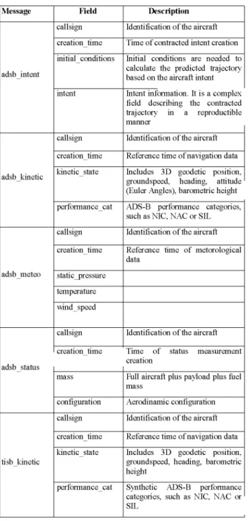
4 ADS-B and TIS-B data formats
Table 1. Message Formats
Message
adsb intent
adsb kinetic
adsb meteo
adsb status
tisb kinetic
Field
callsign
creation time
initial conditions
intent
callsign
creation time
kinetic state
performance cat
callsign
creation time
static pressure
temperature
wind speed
callsign
creation time
mass
configuration
callsign
creation time
kinetic state
performance cat
Description
Identification of the aircraft
Time of contracted intent creation
Initial conditions are needed to calculate the predicted trajectory based on the aircraft intent
Intent information. It is a complex 1 field describing the contracted trajectory in a reproductible manner
Identification of the aircraft
Reference time of navigation data
Includes 3D geodetic position, groundspeed, heading, attitude (Euler Angles), barometric height
ADS-B performance categories, such as NIC, NAC or SIL
Identification of the aircraft
Reference time of metorological data
Identification of the aircraft
Time of status measurement creation
Full aircraft plus payload plus fuel mass
Aerodinamic configuration
Identification of the aircraft
Reference time of navigation data
Includes 3D geodetic position, groundspeed, heading, barometric height
Synthetic ADS-B performance categories, such as NIC, NAC or SIL
ATLANTIDA ADS-B and TIS-B data formats are an extension of available ADS-B and TIS-B formats to include new fields of interest for short term and medium term trajectory prediction. They are:
• Aircraft mass.
• Intent information, in a much more detailed format than previous systems. • Attitude information
• Aerodynamic configuration (Flaps, Landing Gear, ... state)
It should be noted all messages in ATLANTIDA are managed by a SWIM system created for this experimental system. It comprises two modes of operation, one based on the broadcasting of messages (using a DDS approach) and another one based on a request-reply protocol (using CORBA). This SWIM system not only covers ground systems, but also communications within the aircraft air-ground and air-to-air communications between different UAS.
5 Air Surveillance Structure and
Algorithms
The structure of air surveillance system is depicted in Figure 2.
Figure 2. Air Surveillance Internal Structure
The air surveillance system is mainly divided into two parts:
• ADS-B messages compilation and broadcast
• Surrounding aircraft Air surveillance.
• Next we will detail both functions.
5.1 ADS-B Compilation and Broadcast
Air surveillance receives ADS-B data from Flight manager (FM) and navigation systems. In the case of navigation the reception will be periodic with a high data rate (at least for some data fields), and data from FMS will be received asynchronously. This function must maintain a copy in a set of internal registers of the last data of a given kind received, and of the corresponding time stamp, as provided by FM and navigation system.
ADS-B messages are broadcasted at a potentially variable data rate, depending on potentially time-changing FM requirements (we assume all short term conflict alerts, flight conformance monitoring, ... are part of FM). ADS-B messages are broadcasted through SWIM, with adequate communication quality of service (QoS) requirements.
5.2 Surrounding Aircraft Air Surveillance
This function is in charge of obtaining the local to aircraft air picture. It contains three steps:
Next we will detail these subsystems functionality.
5.2.1 Air Surveillance Input Data Server
This subsystem is in charge of receiving ADS-B and TIS-B messages and performing some data filtering in order to provide the rest of the system with messages fulfilling the following conditions:
• ADS-B and TIS-B from a same aircraft will not be processed. If the aircraft is receiving ADS-B messages from a given aircraft (its identifier may be used for it) TIS-B messages should be discarded.
• Messages will not overload surveillance function.
After this, messages are passed to next block.
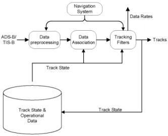
5.2.2 Air Picture Situation Compilation
The Air picture situation block executes the three central processes of Figure 3 (data preprocessing, ADS-B/TIS-B report association and tracking filters)
i
ADS-B/ [ Data |TIS-B *W
f Navigation A
^ System J
\
Data Rates
^ [ Data | J\ Tracking | reprocessing 1 ^ 1 Association 1 ^ 1 Filters I
n
Track State
f*^_^^
Track State & Operational
Data
Track State
Figure 3. Air Picture Situation Architecture
The preprocessing consists in the coordinate transformation and the error covariance estimation for ADS-B kinetic messages. Tracking is performed in stereographic plane whose tangential point is a position near the aircraft position, which jumps every few minutes following aircraft motion. We convert both position and ground speed and track angle information from geodetic coordinates to stereographic projection.
The accuracy of ADS-B position and velocity reports will be expressed in tracking coordinates, taking into account the error models of ADS-B: Accuracy expressed typically following Navigation Accuracy Category (RTCA 260-a) will be translated to a measurement covariance matrix for horizontal position and a variance for vertical position. Therefore, after pre-processing we will have position and velocity measures with their assumed covariances. TIS-B messages will not be filtered, and therefore it is necessary to assess their accuracy.
based tracks and vice versa are defined based on time without ADS-B messages.
There are independent filters for horizontal relative position and for geometric and barometric height. Its utilities are: support prediction function, support association and integrity tests, determine the sufficient update rate, classify the mode of flight (MOF) and reduce measurement noise.
Each track has associated information, which is maintained by the tracking function. Tracking filters only process information related with target cinematic state (ADS-B kinetic and TIS-B messages). In a first approximation only 3D Position and ground velocity are considered for tracking. Other information, from other ADS-B messages, will be updated directly in the track state but not considered for tracking.
The horizontal tracking filter is of Kalman type due to airborne lower processing capabilities. It has a residual based maneuver detector, increasing acceleration variance in a piecewise constant white acceleration model [8] during a fixed time interval after maneuver detection.
There are two independent vertical tracking filters: for barometric and geometric heights respectively. Both filters will be also of Kalman type.
Based on the quality of the estimated track, tracking function computes and communicates to the surveillance input data server the data rate necessary to maintain track quality. In this case, the data server adjust input reports to adapt the input data rate, if it is higher than the demanded one.
5.2.3 Air Surveillance Input Data Server
Finally, the output data server block is in charge to communicate results of the air surveillance function to FM. In our case we consider one means for communication periodic.
It actualizes periodically the track states, synchronized in time, to feed the FM and perform periodic publication of air picture situation to FM.
6 Performance Evaluation
Next we will provide Monte Carlo simulation results from a given pair of aircraft. Both are equipped with quite good Differential-GPS navigation systems. Those simulations are designed
by defining emulated navigation and flight management systems, providing an actual instance of air surveillance system with measures for its calculations.
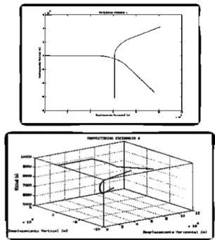
Their trajectories in 2D and 3D are depicted in Figure 4.
Figure 4. Example Trajectories in 2D and 3D
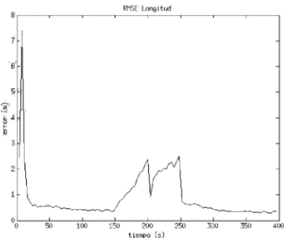
They are two orthogonal trajectories with aircraft with a groundspeed of 300 m/s, and a transversal manoeuvre at 3 m/s2. In vertical dimension, they have a level flight, followed by a descend interval and another level flight. Position and velocity RMS errors for one of the aircraft are depicted in Figures 5 and 6.
RMSE L a t i t u d
5 I 1 1 1 1 1 1 1
4
3,5
3
1.5
-0 5-0 1-0-0 15-0 2-0-0 25-0 3-0-0 35-0 4-0-0 tie.po (s)
8
7
3
r
'0 50 100 150 200 250 300 350 400 tiempo
is)-Figure 6. Latitude Position Error (RMS, in Meters) Along Time (in Seconds)
In position, peak errors in the order of 5 meters are obtained. Regarding groundspeed and Heading, errors bellow 0.15 m/s and 1° are attainable.
Regarding vertical dimension, errors up to 15 meters and 7 m/s appear near the time of vertical mode of flight change.
As no filtering is performed over other magnitudes, such as euler angles, accelerations, mass,
... the quality of those estimates are the same provided by the raw navigation system.
ADS-B quality as the basis for air-to-air surveillance is capable of fulfilling the most demanding surveillance requirements.
7 Conclusion and Future Work
This paper details the experimental development of an air surveillance system to be integrated in ATLANTIDA system, and to experiment with real flight conditions. The system has been developed and our simulated data shows it will fulfill even the most demanding surveillance accuracy requirements. During next few months we will have the actual air surveillance deployment in ATLANTIDA prototype and real data will be obtained and evaluated.
With this experimental deployment, many additional results, especially regarding the use of an air-ground SWIM system as middleware for
RMSE Longitud surveillance communications (with respect to
messages delays, QoS achievement, ...), and the exploitation of surveillance as the basis of automatic negotiation of 4D trajectories and weather monitoring.
As a conclusion, it is clear ADS-B must be improved to include new information enabling for accurate trajectory prediction, especially for nearby aircraft. The final format of the intent/trajectory information to be interchanged is directly related to the negotiation procedures between flight data processing systems within the traffic management systems and the pilot assessment systems to be integrated in the fight management systems.
8 References
[1] ICAO Annex 10: Aeronautical Telecommunications. Volume IV. Surveillance Radar and Collision Avoidance Systems
[2] Technical Verification and Validation of TIS-B using VDL Mode 4. NEAN Update Program
[3] SESAR Consortium website.
[4] Next Generation Air Transportation System (NGATS) Institute website
[5] Manual on detailed technical specifications for the VDL Mode 4 digital link. Draft 2.1. 25 November 2003. EUROCAE.
[6] Manual on the Universal Access Transceiver (UAT): Detailed Technical Specifications, Edition 1. Revision 3.2. 2 March 2005. ICAO
[7] FANS-l/A Operations Manual. Version 4.0. Effective 1. 28 September 2006