Performance of masonry buildings during the 2011
Lorca earthquake
L. Hermanns, A. Fraile, E. Alarcón & R. Álvarez Universidad Politécnica de Madrid, España
SUMMARY:
On Wednesday 11th May 2011 at 6:47 pm (local time) a magnitude 5.1 Mw earthquake occurred 6 km northeast of Lorca with a depth of around 2 km. As a consequence of the shallow depth and the small epicentral distance, important damage was produced in several masonry constructions and even led to the collapse of some of them. Pieces of the facades of several buildings fell down onto the sidewalk, being one of the reasons for the killing of a total of 9 people.
The objective of this paper is to describe and analyze the failure patterns observed in unreinforced masonry buildings ranging from 3 to 8 floors in height. First, a brief description of the local building practices of masonry buildings is given. Then, the most important failure types of masonry buildings are described and discussed. After that, a more detailed analysis of one particular building is presented.
Keywords: Lorca Earthquake, Masonry, Infill, Column Shear Demand, Shear failure
1. INTRODUCTION
The seismic hazard at the city of Lorca, located in the south-east of Spain, can be considered as low to medium. One way to describe the seismic activity of a region consists in presenting a histogram of intensity values of all occurred earthquakes in the region. The resulting graph for the region extending from 37,2 to 38,2 degrees north latitude and from -1.1 to -2.2 degrees west longitude is displayed in Figure 1.
0 20 40 60 80 100 120
IV V VI VII VIII IX X
EMS-98 Intensity
Nu
mbe
r o
f
even
ts
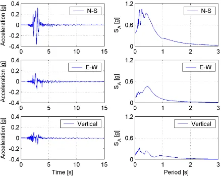
According to the current Spanish Seismic Design Code (NCSE 2002) the PGA considering a return period of 500 years results in 12% g. It is important to note that this PGA value does not correspond to a rock site but to one with stiff soil i.e. soil type B according to EN-1998. A seismograph station of the National Seismic Network located at only 3 km from the epicentre registered peak accelerations of 36% g in N-S direction, 15% g in E-W direction and 12% g in vertical direction. In Figure 2 the acceleration time histories as well as the elastic response spectra for 5% damping are displayed.
Figure 2. Acceleration time histories registered at Lorca station and corresponding elastic response spectra for 5% damping
Reinforced concrete frame buildings with masonry infill walls are very common in Spain. Many of these buildings were damaged by the earthquake however, in terms of catastrophic failures the situation did not reach dramatic proportions. Actually only one building collapsed; a recently built apartment house. Only two hours before the main event occurred, a smaller earthquake was registered. This smaller event already caused some damage to several buildings and was the reason for the evacuation of the building that collapsed due to the damage suffered during the main event.
The situation on the streets was quite similar throughout the whole town. Figure 3 displays the situation of one of the streets in Lorca immediately after the main event took place.
Many pieces of the facades that fell down during the earthquake injured a lot of persons. In some occasions façade infill panels located at upper floors and roof parapets collapsed and fell onto the ground. Two different failure mechanisms are thought to be responsible for their collapse.
In the case of roof parapets, chimneys and to a minor extent infill panels at upper floors the failure was caused by inertia forces acting out-of-plane. It is well known that the resistance of masonry walls to out-of-plane moments is much lower than that of R.C. frames. As a consequence the interaction between the frames and the infill panels is very limited in this particular loading scenario as the failure of the infill panel changes the structural properties at a very low load level. Regarding unreinforced roof parapet walls some codes (FEMA 2011) point out the significant falling hazard related to this type of architectural components. Figure 4 shows one of the parapets that partially collapsed confirming thereby the importance of studying the seismic behaviour of non-structural components. The structure of this particular building did not suffer significant damage whereas the roof parapet almost completely collapsed.
Figure 4. Building with a almost completely collapsed parapet wall
This type of incoherence in terms of the seismic behaviour of different components of the same building should be avoided. It is important to note that the acceleration at roof level may be significantly higher than that at ground level due to the dynamic properties of the building. In addition, the bending moment capacity at the contact surface at roof level is usually quite small if the parapet wall is not adequately anchored. Not only parapet walls failed at this load level but also chimneys on flat roofs.
Figure 5. Damaged masonry infill walls at ground floor
2. FAILURE PATTERNS OF NON-STRUCTURAL MASONRY WALLS
After the earthquake a damage assessment was performed revealing that most of the damage may be classified as well known failure modes due to the interaction between the frame structure and interior partitions or façade elements. A distinction of these failure modes may be drawn depending on whether the initial combination of the lateral resistive elements is responsible or whether the progressive failure of some of them and the accompanying change of the stiffness distribution leads to an excessive seismic demand. The following 5 points belonging to the first group have been observed in Lorca.
⎯ Some buildings didn’t seem to have effective mechanisms to resist lateral loads. However, most of them did not suffer excessive damage. In these cases the stiffness of the masonry infill panels add to the one of the frame structure and the infill panels resisted quite well. The damage distribution was similar to the one observed in buildings with an effective lateral load resistance mechanism.
⎯ Asymmetrical horizontal stiffness distribution leading to torsion moments. This was quite often the case in corner buildings of apartment blocks. The only building that collapsed during the earthquake falls into this category. Other corner buildings with asymmetrical horizontal stiffness distribution suffered substantial damage.
⎯ Soft storey mechanisms due to infill panels with lower stiffness at the ground floor level and panels with higher stiffness at upper floors. In many cases the interstory height at ground floor level was significantly higher than that of the upper floors favouring thereby the generation of a Soft storey mechanism.
⎯ Shear force concentration in combined systems consisting of R.C. columns and masonry shear walls (see Figure 8). In order to estimate realistic shear forces during the design phase it is crucial to take the stiffness of the masonry wall into account however, quite often infill panels are not considered in the structural building model that is used for the seismic response analysis. It is quite common that only one infilled bay exists at ground level. In this case the infill is usually part of the elevator core walls.
A progressive failure of the infill panels or the frame columns and the accompanying change of the stiffness distribution is thought to be responsible for the following 2 failure patterns observed in Lorca.
⎯ Formation of soft storey mechanisms due to the progressive degradation of the infill panels located at ground floor levels.
⎯ Column failure due to interaction forces between the masonry walls and the RC columns. The adjacent frame columns are usually not designed considering different failure modes of the masonry walls and the resulting force redistribution.
2.1. Reasons for the formation of Soft Storey mechanisms
The importance of taking into account the stiffness contribution of masonry infill panels when estimating the design forces is well known however, 40 years ago the situation was different.
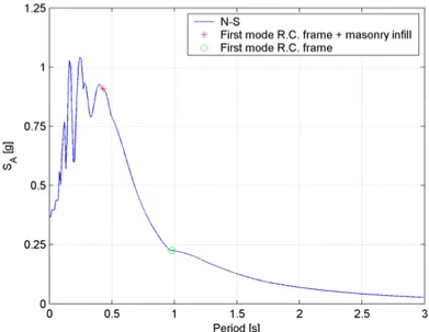
In order to study the formation of a Soft-Storey mechanism the example of a typical eight-floor apartment building is used. In one direction there are four 5m span bays and in the other the spacing between adjacent columns is 6m. The height of the ground floor is 4.25 m and that of the others 3.25 m. The storey masses were estimated using approximate formulas and the columns were designed essentially only for gravity loads as was practice in the 1970’s. The resulting fundamental period of the bare frame structure is approximately 1 s (0.98 s). If masonry infill is added to one bay on all floors the period reduces to 0.43 s. In Figure 6 the response spectrum of the North-South component is presented and both periods are marked.
Figure 6. Response spectrum of the N-S component of the 2011 Lorca earthquake
strength of conventional masonry. The intact infill panel reduces the fundamental period of the structure which results in considerable seismic forces that finally cause the failure of the masonry infill at a quite early stage of the earthquake. In order to study what happens after the failure of the masonry infill at ground level its stiffness is drastically reduced and the transient dynamic analysis is repeated i.e. the damaged structure is subjected to the seismic loads that result from the North-South component of the Lorca earthquake. The resulting fundamental period is 0.68 s and the maximum base shear force reaches 2.5 MN.
This simple example may explain the high number of damages observed in shear and partition walls.
2.2. Column failure
The interaction between the infill panels and the surrounding frame structure during a seismic event is an active research topic and quite challenging to simulate. At the design stage of many of the existing buildings in Lorca, however, this interaction was taken into account only approximately if at all. As a consequence the columns i.e. the most important structural elements for gravity loads are subjected to loads that they were not designed for. In this context, it is worth to remember that according to (NEHRP 2008) column shear failure is the most frequently cited cause of concrete building failure and collapse in earthquakes!
Depending on the failure mode of the infill panel different types of loads at different locations act on the columns. In many cases the resistance of the infill panels is small enough so that the forces that have to be transferred to the frame structure can be supported without any problem. However, there is still the problem of the significant falling hazard related to a damaged infill panel. The situation is different if the infill panels are capable of supporting high loads. Due to the high in plane stiffness of the masonry infill the forces that have to be redistributed i.e. transferred from the infill to the frame structure are very important. In addition, the load redistribution occurs very rapidly and this fact contributes to the generation of brittle failures of columns. Today’s design criteria (EN1998-1 2004) as well as standard text books on the seismic design of reinforced concrete and masonry buildings like (Paulay & Priestley 1992) insist that brittle failures of structural elements shall be avoided.
In very few cases the frame structure failed whereas the infill panels were intact after the earthquake. In some cases both the frame structure and the infill panel showed similar resistance values so that the origin and sequence of failure could not exactly be identified.
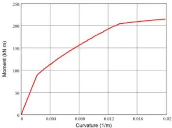
As an example, suppose a concrete column with square cross section of 40 x 40 cm and a compressive strength of 25 MPa (5% cylinder strength fck) that is reinforced with 3 bars of diameter 16 mm on each face subjected to an axial load that results in an average compressive stress of 5 MPa. In Figure 7 the corresponding moment-curvature diagram is displayed.
The maximum value reaches 215 kNm. Based on equilibrium considerations of the capacity design method, see Figure 8, and considering a floor height h of 4 m, the corresponding maximum shear force is 107.5 kN.
Figure 8. Estimation of the shear demand in a column
The shear capacity of this column without shear reinforcement is according to the Spanish Seismic Design Code (NCSE 2002) 182.5 kN. Considering the same limit values for the maximum moment and the shear capacity of the column a floor height of 2.36 m would be necessary to increase the shear demand to an extent that the shear capacity is exceeded when reaching the maximum moment. However, this floor height is much lower than the limit value established by the urban building standards. This means that, in general, a column shear failure may be avoided if the capacity design approach is followed and properly detailed shear reinforcement is designed and provided.
In the following section the interaction between frame structure and infill panels will be further discussed.
3. INTERACTION OF STRUCTURE AND INFILL PANEL
According to (WHE 2006) the performance of buildings with masonry infill in the frame panels in past earthquakes has revealed that the presence of masonry infill walls is typically detrimental for the seismic performance of the building. The numerical simulation of whole buildings in their elastic and post-elastic ranges up to failure is even today quite challenging. Usually macro models are used when whole structures are analyzed whereas micro models are only employed when laboratory tests of structural elements are simulated. When using macro models it should be remembered that these models are generally unable to capture some of the failure modes described in the following.
3.1. Failure of the beam-column junction
Figure 9. Failure at the construction joint of beam-column connection
Failures of the contact surface were observed in several occasions (see Figure 10).
Figure 10. Examples of failure at the construction joint of a beam-column connections
This type of failure was observed particularly often in end bays of the exterior R.C. frames.
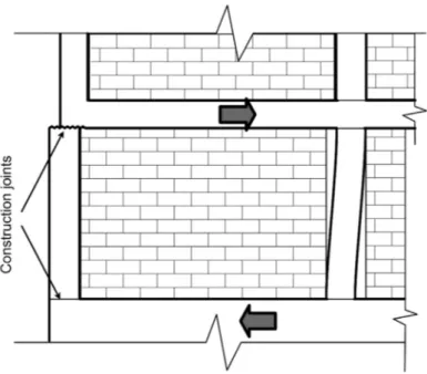
3.2. Shear failure of the infill panel
This type of failure is particularly dangerous because of the damage that is caused to the compression zone of the infill panel i.e. the load carrying strut in an equivalent strut model. If the failure results in the formation of two struts like indicated in Figure 11 b important forces act on the column sections almost at mid-floor height.
Figure 11. Force transmission before (Fig. 11 a) and after (Fig. 11 b) shear failure of the infill panel
3.3. Failure of the column and the infill panel
In general crack propagation in the infill panels indicates the position of the traction diagonal that connects two beam-column connections however, in some cases the cracks in the infill panels developed laterally displaced crossing the column at mid height like in Figure 12 b.
Figure 12. Example of cracks crossing a column at mid-floor height. Building (Fig. 12 a) Detail (Fig. 12 b)
4. CONCLUSIONS
The damages caused by the Lorca earthquake to structures that were built during the last 20 years indicate that lessons that should have been learned from previous seismic events have been, at least partially, ignored or misinterpreted. If R.C. frames are built with infill walls but their effect is not accounted for during design calculations and the structural analysis, the consequences may be catastrophic.
may result insufficient even for moderate earthquakes. This raises the question whether the seismic load case has been adequately studied.
If the masonry infill panels are not included in the structural model that is used to study the seismic behaviour of the building, the non-structural infill walls should be designed and built with gaps to accommodate frame drifts; this solution is also known as isolated infill.
The falling hazard of damaged parapet walls is well known and addressed in several guidelines like (FEMA 2011). The importance of non-structural elements in the context of a seismic analysis should be evaluated taking into account their damage potential, not their cost.
REFERENCES
Verderame, G.M; Luca, F; Ricci, G; Manfredi, G. (2011). Preliminary analysis of a soft-
storey mechanism after the 2009 L’Aquila earthquake. Earthquake Engineering & Structural Dynamics.
40:8, 925–944
NCSE 2002 Norma de Construcción Sismoresistente: Parte general y edificación (2002) , Ministerio de Fomento, España (www.fomento.es)
Cabañas Rodriguez,L.; Carreño Herrero, E.; Izquierdo Alvarez, A.; Martínez Solares, J.M.; Capote del Villar, R.; Martínez Díaz, J.; Benito Oterino, B.; Gaspar Escribano, J.; Rivas Medina, A.; Garcia Mayordomo, J.; Pérez López, R.; Rodriguez Pascua, M.A.; Murphy Corella, P. (2011) INFORME DEL SISMO DE LORCA DEL 11 DE MAYO DE 2011, Instituto Geográfico Nacional
(www.ign.es/ign/resources/sismologia/Lorca.pdf)
FEMA E-74 Reducing the Risks of Nonstructural Earthquake Damage- A Practical Guide (2011), Fourth Edition, FEMA (www.fema.gov)
EN1998-1 2004 “Eurocode 8: Design of structures for earthquake resistance. Part 1 General rules, seismic actions and rules for buildings”, EUROPEAN COMMITTEE FOR
STANDARDIZATION
Murty CVR, Brzev S, Faison H, Comartin CD and Irfanoglu A “AT RISK: The Seismic Performance of Reinforced Concrete Frame Buildings with Masonry Infill Walls (2006), WHE, ISBN: 1-932884-22-X Moehle, Jack P., Hooper, John D., and Lubke, Chris D. (2008) Seismic design of reinforced concrete special
moment frames: a guide for practicing engineers, NEHRP Seismic Design Technical Brief No. 1 Paulay T, Priestley MJN (1992) Seismic Design of Reinforced Concrete and Masonry