UNIVERSIDAD POLITÉCNICA DE MADRID
ESCUELA TÉCNICA SUPERIOR
DE
INGENIEROS DE TELECOMUNICACIÓN
DEVELOPMENT OF EFFICIENT TECHNIQUES FOR
THE ANALYSIS AND DESIGN OF ANTENNAS IN
DUAL-REFLECTARRAY CONFIGURATION
TESIS
DOCTORAL
Carolina Tienda Herrero
Ingeniera de Telecomunicación
DEPARTAMENTO DE ELECTROMAGNETISMO
Y TEORÍA DE CIRCUITOS
ESCUELA TÉCNICA SUPERIOR
DE
INGENIEROS DE TELECOMUNICACIÓN
TESIS
DOCTORAL
DEVELOPMENT OF EFFICIENT TECHNIQUES FOR
THE ANALYSIS AND DESIGN OF ANTENNAS IN
DUAL-REFLECTARRAY CONFIGURATION
Autora:
Carolina Tienda Herrero
Ingeniera de Telecomunicación
Director:
José Antonio Encinar Garcinuño
Doctor Ingeniero de Telecomunicación Catedrático de Universidad
Codirector:
Manuel Arrebola Baena
Doctor Ingeniero de Telecomunicación Profesor Titular de Universidad
TESIS DOCTORAL: Development of efficient techniques for the analysis and design of antennas in dual-reflectarray configuration.
AUTOR: Carolina Tienda Herrero
Ingeniera de Telecomunicación
DIRECTOR: José Antonio Encinar Garcinuño
Doctor Ingeniero de Telecomunicación Catedrático de Universidad
CODIRECTOR: Manuel Arrebola Baena
Doctor Ingeniero de Telecomunicación Profesor Titular de Universidad
DEPARTAMENTO: Electromagnetismo y Teoría de Circuitos Universidad Politécnica de Madrid
El Tribunal de Calificación, compuesto por:
PRESIDENTE:
VOCALES:
VOCAL SECRETARIO:
VOCALES SUPLENTES:
Acuerda otorgarle la CALIFICACIÓN de:
ACKNOWLEDGMENT
First of all I would like to show my most sincere gratitude to my advisor Prof. José A. Encinar.This thesis work could not have been accomplished without his insight, guidance and patience. Thank you for being always there, no matter where, in Madrid or Belfast.
I am indebted to my advisor Manuel Arrebola Baena for his support throughout the whole process of this thesis. Thank you for being available any time, seven days per week. Thank you for encouraging me in the “moments of darkness”.
I would like to thank all the staff of the Departamento de Electromagnetismo y Teoría de Circuitos of Universidad Politécnica de Madrid. Special thanks go to Mariano. Without “his beloved” lab and his great building abilities none of the antenna reflectarrays prototypes would have ever seen the light. From him I learned hands-on laboratory skills and I really enjoyed my time while doing some hardware work.
I owe my gratitude to the external committee members, for the time and effort to read and evaluate this thesis: Robert Cahill, Elena Saenz and Germán León.
This thesis is also the result of an educational visit to the European Space Agency (ESTEC), under the supervision of Dr. Giovanni Toso and Cyril Mangenot. Thank you for hosting me in your department during that period.
I am also grateful to all the colleagues I got the opportunity to interact with during this time at the University of Madrid, either sharing the office, discussing on technical topics or entertaining lunch, coffee breaks and chinos. In particular I would like to mention:
Eduardo Carrasco, Carlos Alberto Leal, Bilal Eljaafari, Jose Enrique, Pedro Robustillo, Ignacio Echeveste, Gerardo Pérez Palomino, Leandro de Haro, Jesús María Rebollar, Jose Ramón and Jesús Grajal.
Finally, I would like to thank many friends for their support during the last years. People, who despite the distance, are close to me: Desi, Rosi, Adrián, CaroCo, EvaP, Vane, Marina, Cristi, Bea, Ruth, Loli and Rafael. And also thanks to my friends from here (Madrid) with whom I have shared part of my life: Yayo, Germán, Julio, Gonzalo, Elena, Bea, Pili and Alfonso.
ABSTRACT
This thesis contributes to the analysis and design of printed reflectarray antennas. The
main part of the work is focused on the analysis of dual offset antennas comprising two
reflectarray surfaces, one of them acts as sub-reflector and the second one acts as
main-reflector. These configurations introduce additional complexity in several aspects
respect to conventional dual offset reflectors, however they present a lot of degrees of
freedom that can be used to improve the electrical performance of the antenna. The
thesis is organized in four parts: the development of an analysis technique for
dual-reflectarray antennas, a preliminary validation of such methodology using equivalent
reflector systems as reference antennas, a more rigorous validation of the software tool
by manufacturing and testing a dual-reflectarray antenna demonstrator and the practical
design of dual-reflectarray systems for some applications that show the potential of
these kind of configurations to scan the beam and to generate contoured beams.
In the first part, a general tool has been implemented to analyze high gain antennas
which are constructed of two flat reflectarray structures. The classic reflectarray
analysis based on MoM under local periodicity assumption is used for both sub and
main reflectarrays, taking into account the incident angle on each reflectarray element.
The incident field on the main reflectarray is computed taking into account the field
developed, one which employs a simple approximation to reduce the computer run time,
and the other which does not, but offers in many cases, improved accuracy. The
approximation is based on computing the reflected field on each element on the main
reflectarray only once for all the fields radiated by the sub-reflectarray elements,
assuming that the response will be the same because the only difference is a small
variation on the angle of incidence. This approximation is very accurate when the
reflectarray elements on the main reflectarray show a relatively small sensitivity to the
angle of incidence.
An extension of the analysis technique has been implemented to study dual-reflectarray
antennas comprising a main reflectarray printed on a parabolic surface, or in general in
a curved surface.
In many applications of dual-reflectarray configurations, the reflectarray elements are in
the near field of the feed-horn. To consider the near field radiated by the horn, the
incident field on each reflectarray element is computed using a spherical mode
expansion. In this region, the angles of incidence are moderately wide, and they are
considered in the analysis of the reflectarray to better calculate the actual incident field
on the sub-reflectarray elements. This technique increases the accuracy for the
prediction of co- and cross-polar patterns and antenna gain respect to the case of using
ideal feed models.
In the second part, as a preliminary validation, the proposed analysis method has been
used to design a dual-reflectarray antenna that emulates previous dual-reflector antennas
in Ku and W-bands including a reflectarray as subreflector. The results for the
dual-reflectarray antenna compare very well with those of the parabolic reflector and
reflectarray subreflector; radiation patterns, antenna gain and efficiency are practically
the same when the main parabolic reflector is substituted by a flat reflectarray. The
results show that the gain is only reduced by a few tenths of a dB as a result of the
ohmic losses in the reflectarray. The phase adjustment on two surfaces provided by the
dual-reflectarray configuration can be used to improve the antenna performance in some
applications requiring multiple beams, beam scanning or shaped beams.
Third, a very challenging dual-reflectarray antenna demonstrator has been designed,
manufactured and tested for a more rigorous validation of the analysis technique
main-reflectarray in the near field one to each other, so that the conventional far field
approximations are not suitable for the analysis of such antenna. This geometry is used
as benchmarking for the proposed analysis tool in very stringent conditions. Some
aspects of the proposed analysis technique that allow improving the accuracy of the
analysis are also discussed. These improvements include a novel method to reduce the
inherent cross polarization which is introduced mainly from grounded patch arrays.
It has been checked that cross polarization in offset reflectarrays can be significantly
reduced by properly adjusting the patch dimensions in the reflectarray in order to
produce an overall cancellation of the cross-polarization. The dimensions of the patches
are adjusted in order not only to provide the required phase-distribution to shape the
beam, but also to exploit the crosses by zero of the cross-polarization components.
The last part of the thesis deals with direct applications of the technique described. The
technique presented is directly applicable to the design of contoured beam antennas for
DBS applications, where the requirements of cross-polarisation are very stringent. The
beam shaping is achieved by synthesithing the phase distribution on the main
reflectarray while the sub-reflectarray emulates an equivalent hyperbolic subreflector.
Dual-reflectarray antennas present also the ability to scan the beam over small angles
about boresight. Two possible architectures for a Ku-band antenna are also described
based on a dual planar reflectarray configuration that provides electronic beam scanning
in a limited angular range. In the first architecture, the beam scanning is achieved by
introducing a phase-control in the elements of the sub-reflectarray and the
main-reflectarray is passive. A second alternative is also studied, in which the beam scanning
is produced using 1-bit control on the main reflectarray, while a passive subreflectarray
is designed to provide a large focal distance within a compact configuration. The system
aims to develop a solution for bi-directional satellite links for emergency
communications. In both proposed architectures, the objective is to provide a compact
RESUMEN
Una antena de tipo reflectarray está compuesta de una fuente primaria que ilumina una
superficie reflectora plana o curva, formada por una agrupación de elementos radiantes
impresos. Un diseño apropiado de estos elementos permite modificar la distribución de
fase del campo reflejado, en la superficie reflectora, produciendo un haz colimado o
conformado en una dirección determinada. La fase del campo reflejado es el resultado
de la combinación de la fase del campo incidente y la del coeficiente de reflexión para
cada elemento-.
Los arrays de fase (phased arrays) y los reflectores parabólicos son comúnmente
utilizados en la mayoría de las aplicaciones de alta ganancia, como el radar o las
comunicaciones de larga distancia. Sin embargo, las antenas reflectarray presentan
ciertas características adicionales que las hacen atractivas para estas aplicaciones.
Debido a que son antenas impresas, los reflectarrays planos son más ligeros y ocupan
menos volumen que los reflectores parabólicos o conformados. Las pérdidas óhmicas en
los reflectarrays dependen del factor de disipación del sustrato y de la geometría del
parche. En particular, para un reflectarray de dos o tres capas de parches apilados las
pérdidas son comparables a las de un reflector parabólico. Por otra parte, los
reflectarrays se pueden utilizar para generar haces conformados usando procesos de
fabricación sencillos y bien conocidos que se han venido utilizando en circuitos
generar haces conformados, pero para su construcción requieren el desarrollo de
costosos moldes que deben ser diseñados y fabricados específicamente para cada
misión, sin posibilidad de reutilización, además de hacer más lento el proceso de
desarrollo de una antena con estas características.
La principal limitación de las antenas reflectarrays es su reducido ancho de banda,
provocado por el comportamiento en banda estrecha de los elementos impresos y por la
diferencia de caminos desde el alimentador hasta cada uno de los elementos del
reflectarray, denominada diferencia espacial de retardo de fase. En los últimos años se
han propuesto varias soluciones para aumentar el ancho de banda de los elementos, que
es el factor más limitante en los reflectarrays de tamaño moderado. Así se han
alcanzado hasta un 15% de ancho de banda por medio de distintas técnicas, como por
ejemplo el uso de varias capas impresas, cada una de ellas con parches de diferentes
tamaños. Otra posibilidad es el uso de los llamados parches acoplados por ranura a línea
de retardo que permiten reducir la diferencia espacial de retardo de fase al insertar una
ruta física que produce un retraso de tiempo real.
Las antenas de doble reflectarray proporcionan control de fase en las dos superficies
reflectoras gracias a lo cual se extiende la aplicabilidad y el rendimiento de las antenas
reflectarray. De esta manera se pueden diseñar antenas con haces múltiples con escasa
degradación. También permite utilizar el principio de la antena bifocal o generar haces
conformados. Otra gran ventaja de las antenas de doble reflectarray es que están
compuestas de reflectores planos que pueden ser fácilmente plegados de manera
compacta siendo esta una característica muy conveniente en aplicaciones de satélite.
Los sistemas de doble reflectarray también pueden proporcionar capacidades de
reconfiguración, gracias al uso de interruptores micro-electro-mecánicos (MEM) o
diodos PIN. Algunas de las aplicaciones de estas antenas reconfigurables son los
Radares de Apertura Sintética (SAR), misiones de teledetección radiométrica o
misiones de transmisión directa vía satélite (DBS) usando antenas de haces
conformados y reconfigurables.
Para aplicaciones en bandas milimétricas y sub-milimétricas, el barrido electrónico se
puede lograr mediante reflectarrays basados en cristales líquidos, donde la fase del
campo reflejado se controla mediante la tensión de polarización aplicada a los cristales
La tesis se divide en tres partes principales. La primera se corresponde con la
implementación y descripción de una técnica de análisis para configuraciones de doble
reflectarray. Se han implementado dos versiones de la técnica: una versión en la que se
emplean ciertas aproximaciones que producen un ahorro substancial de tiempo de
cálculo y una segunda versión que aunque permite tener mayor precisión en los
resultados penaliza la eficiencia computacional. La segunda parte está dedicada a la
validación de dicha técnica de análisis, en primer lugar mediante comparaciones con
sistemas reflectores equivalentes. Posteriormente, se realiza una validación completa
mediante el diseño, fabricación y medida de una antena de doble reflectarray. Por
último, se diseñan distintas antenas de doble reflectarray, que muestran el potencial de
estas configuraciones para generar haces conformados y hacer barrido electrónico del
haz.
Técnica de análisis para antenas de doble reflectarray
Se ha desarrollado una técnica modular de análisis de antenas basadas en
configuraciones con dos reflectarrays que incluye el análisis del alimentador, del
subreflectarray y del reflectarray principal, así como el cálculo del diagrama de
radiación en campo lejano. La Fig. R.1 muestra una configuración genérica de la antena
propuesta, en este caso se trata de una configuración offset si bien la formulación puede
aplicarse a geometrías centradas. El modelado del alimentador basado en funciones que
modelan el campo lejano consigue normalmente una buena precisión. No obstante, hay
casos en los que los elementos del subreflectarray se encuentran en la zona de Fresnel
del alimentador, por lo que la aproximación de campo lejano deja de ser válida y es
conveniente utilizar modelos de campo cercano que pueden estar basados en, por
Fig. R.1. Esquema de un sistema de doble reflectarray.
El sub reflectarray se analiza elemento a elemento, teniendo en cuenta la periodicidad
local y el ángulo de la onda incidente proveniente del alimentador. El campo total
reflejado en los elementos del sub reflectarray se calcula mediante el método de los
momentos (MoM) como la superposición de los campos radiados por los parches y el
campo reflejado en la estructura dieléctrica multicapa y considerando las pérdidas de
disipación del reflectarray.
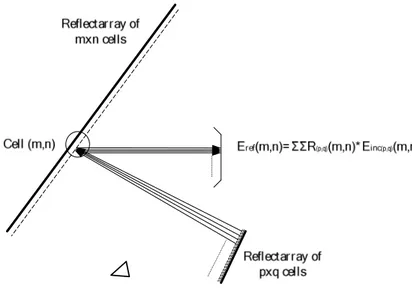
El reflectarray principal se analiza usando la misma técnica empleada para el
sub-reflectarray. Para calcular el campo incidente en las celdas del reflectarray principal, se
tienen en cuenta las contribuciones de todos los elementos del sub-reflectarray. En
principio, los ángulos de incidencia de todos los elementos del sub-reflectarray se
consideran iguales, lo que supone una simplificación en la técnica de análisis. Dicho
ángulo de incidencia se calcula utilizando el centro del sub-reflectarray como origen del
campo incidente. Gracias a esta simplificación se reducen drásticamente los tiempos de
cálculo manteniendo una precisión suficiente en los resultados obtenidos para las
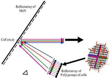
Sin embargo, la técnica de análisis contempla la posibilidad de hacer un análisis más
preciso para las configuraciones que así lo requieran. Este es el caso de los sistemas en
los que el reflector principal se encuentre en la zona de Fresnel del sub-reflector y
cuando la respuesta de los elementos del reflectarray principal es muy dependiente del
ángulo de incidencia. Para llevar a cabo dicho análisis, los elementos del
sub-reflectarray se agrupan en pequeños sub-arrays de elementos y el campo incidente en el
reflector principal se descompone en ondas radiadas por cada grupo con sus ángulos de
incidencia correspondientes.
En el cálculo de la polarización cruzada, se tienen en cuenta dos componentes: la
generada por los parches impresos y la debida a la geometría de la antena (proyecciones
de campo). A pesar de que la componente contrapolar del campo generada por los
parches en general es baja, es necesario considerarla en el análisis y diseño del
reflectarray, sobre todo en aquellas aplicaciones que tienen requisitos estrictos en el
nivel de polarización cruzada.
Finalmente, el diagrama de radiación de la antena completa se calcula a partir del
campo reflejado por el reflectarray principal, aplicando el Segundo Principio de
Equivalencia y un algoritmo basado en la FFT bidimensional.
Validación de la técnica de análisis
La principal dificultad en la validación de la técnica de análisis recae en el hecho de que
no existen en la literatura medidas de antenas de doble reflectarray. Por ello, la
validación se ha realizado en dos etapas.
En primer lugar se han usado como referencia dos antenas diferentes de doble reflector,
compuestas por un reflector principal parabólico y un sub reflectarray, documentadas
anteriormente en la literatura. La validación se lleva a cabo mediante la sustitución del
reflector parabólico principal de las antenas de referencia por un reflectarray
equivalente, diseñado para emular el comportamiento del reflector parabólico principal.
La primera configuración consiste en un doble reflectarray en banda Ku, donde el
sub-reflectarray introduce una constante de fase (que funciona como un reflector plano
metálico) y el reflectarray principal colima el haz, emulando el comportamiento del
reflector parabólico. Comparando los resultados de la técnica de análisis con los de la
eficiencia y los diagramas de radiación son prácticamente las mismas cuando el
reflector principal de la antena de referencia se sustituye por un reflectarray plano.
El segundo diseño es un doble reflectarray en configuración dual-offset, que genera un
haz colimado a 94GHz que se desvia 5º en azimut introduciendo una fase progresiva en
el reflectarray que actúa como subreflector. En este caso se observa que el campo
cercano radiado por la bocina debe ser incluido en el análisis para proporcionar
resultados similares a los documentados en la literatura.
Ambos ejercicios de validación demuestran la viabilidad de las dos antenas con doble
reflectarray, en las que el reflectarray principal se ha diseñado para emular el
comportamiento de un reflector convencional.
Fig. R.2. Esquema de una configuración de doble reflectarray. El reflectarray principal se ha superpuesto con su reflector parabólico equivalente
Dm
Cm
Fm Oblique
aperture
Feed horn XA
YA ZA
XSR
ZSR
YR
Virtual Feed Main-ref lectarray
Dm
Cm
Fm Oblique
aperture
Feed horn XA
YA ZA
X
Z
YSR
Virtual Feed Main
parabolic ref lector
XMR
ZMR
YMR
Diseño, fabricación y medida de un prototipo de doble reflectarray
La validación de las técnicas de análisis y diseño propuestas en esta tesis se completa en
una segunda etapa mediante el diseño, construcción y medida de una antena de doble
reflectarray basada en una geometría compacta. Este es el único método posible para
validar rigurosamente las técnicas de análisis desarrolladas en esta tesis.
La geometría de la antena se ha seleccionado de forma que sea capaz de llevar al límite
la validez de la técnica de análisis. Así la configuración propuesta tiene los tres
elementos (bocina, reflectarray principal y sub reflectarray) muy próximos unos de
otros, que hace que las aproximaciones convencionales de campo lejano no sean
adecuadas para el análisis de esta antena. Asimismo, los dos reflectarrays se han
definido para emular los reflectores de la antena equivalente, que producen un haz
enfocado dirigido en la dirección dada por θ = 28º, cumpliendo las condiciones
Mizugutchi.
Dos diseños con la misma geometría se han llevado a cabo. El primer prototipo usa un
sub reflectarray de dos capas con tamaño de parche diferente en cada capa y un reflector
principal de una sola capa, debido a que el rango de fase necesario para el reflectarray
principal es más reducido. Los elementos se han diseñado con el objetivo de reducir la
polarización cruzada, forzando a la cancelación de una parte de dicha componente. El
prototipo de doble reflectarray se ha construido y medido en cámara anecoica, ver Fig.
R.3. Los resultados de la simulación tienen una concordancia muy buena con las
medidas, salvo por algunas pequeñas diferencias en los lóbulos laterales causados por
los errores de tolerancia del proceso de fabricación. Este prototipo ofrece una
discriminación de la polarización cruzada mayor de 35 dB y funciona en un amplio
ancho de banda de frecuencia: de 12,2 GHz a 15 GHz.
Con objeto de mejorar las prestaciones de ancho de banda y polarización cruzada de la
antena construida, se ha realizado un segundo diseño en el que se incluyen dos capas en
el reflectarray principal. Seleccionando el tamaño adecuado de los parches se puede
conseguir que los nulos y el cambio de signo de la polarización cruzada se cancelen en
este nuevo diseño de doble reflectarray. De esta manera se consigue una reducción
sustancial en los niveles de polarización cruzada, con lo que se obtiene una
discriminación contrapolar mejor de 37 dB en un ancho de haz de 3dB para las dos
A partir de la configuración anterior de doble reflector, se ha diseñado una antena que
genera un haz conformado para una cobertura Europea utilizada definida por Eutelsat
para aplicaciones DBS (Direct Broadcast Satellite). En este caso, la distribución de fase
en el reflectarray principal se ha sintetizado de manera que proporcione cobertura sobre
toda Europa. La antena puede trabajar en polarización dual lineal y los diagramas
resultantes cumplen los requisitos de cobertura en la banda de frecuencia de
transmisión. Estos resultados demuestran como la configuración de doble reflectarray
cumple con los requisitos de las antenas de DBS tanto en la banda de transmisión como
en la de recepción.
Fig. R.3. Demostrador de doble reflectarray ubicado en la cámara anecoica
Aplicación de un doble reflectarray para barrido en banda Ku
En esta tesis también se ha abordado el análisis de dosarquitecturas de antenas de doble
reflectarray en banda Ku capaces de proporcionar barrido electrónico del haz en un
rango angular limitado. Los diseños han sido desarrollados en el marco del proyecto
RESKUE (contrato de la ESA n º 22078/08/NL/ST) en colaboración con la Agencia
Espacial Europea(ESA)yRF-Microtech. El sistematiene como objetivo desarrollaruna
estación portátil para enlaces vía satélite bidireccionales y con capacidad de
apuntamiento automática, útiles en comunicaciones de emergenciaen lugares remotos,
donde las infraestructuras deotros medios de telecomunicación no estén disponibles o sean
Los requisitos impuestos dentro del proyecto RESKUE son que la arquitectura propuesta
debe proporcionar unaópticacompacta y con cierta facilidad de plegadoy desplegado.
Igualmente el sistema debe proveer la capacidadautomática de apuntamiento a un satélite
geoestacionarioen unrango angular limitado. Finalmente, el sistema se debe diseñarpara
proporcionar un haz directivo en las bandas de recepción (10.70 - 12.75 GHz) y
transmisión (14.0 - 14.5GHz), para lo que se han propuesto dos soluciones. En la
primera, el reflectarray principal espasivo y el barrido del hazse consiguemediante la
introducción de control de fase en los elementos del sub-reflectarray. Los principales
inconvenientesobservados en esta configuración son que el reflectarray principal tiene
que ser de gran tamaño y que es difícil diseñar un elemento de reflectarray de
polarización dualqueabarque las bandas de transmisión y recepción.
Para superar estos problemas, se ha estudiado una segunda configuración que cuenta con
unsub-reflectarray pasivo de doble capa y unreflectarrayprincipal concontrol electrónico
de 1-bit. El sub reflectarray pasivo se diseña con el único objetivo de conseguir una
configuración compacta para un sistema parabólico conuna distancia focalgrande. Esta
configuración presenta pequeños errores en la fase que han sido evaluadas a diferentes
frecuencias.En caso de considerarse necesario, estos errores se pueden reducirmediante
la inclusión de una tercera capa en el sub reflectarray pasivo. Los resultados
preliminares muestranun rendimiento satisfactorio de la antenaen las bandas transmisora
y receptora.
Antena de doble reflectarray con reflectarray principal parabólico
Una alternativa a la antena de doble reflectarrayconsiste en reemplazar el reflectarray
plano principal por un reflectarray impreso sobre una superficie curva en general y, en
particular, sobre una superficie parabólica. Así se ha propuesto una configuración
compuesta de tres componentes: una fuente primaria, un sub-reflectarray plano y un
reflectarrayprincipalparabólico, como se muestra en la Fig. R.4 Enesta configuración el
reflectarrayprincipal sólo necesita introducir pequeños ajustes de fase ya que la geometría
Fig. R.4. Esquema de una configuración de doble reflectarray con reflectarray principal parabólico
Para analizar esta antena, se ha implementado una extensión de la técnica de análisis
para antenas planas de doble reflectarray que permite analizar un reflectarray principal
parabólico. Dicha extensión tambiénpuedeaplicarse a configuraciones más genéricas en la
que el sub-reflectarray, el reflectarray principal, o ambos están impresos sobre cualquier
tipo desuperficie curva.
Con objeto de validar la técnica de análisis se ha empleado un único reflectarray sobre
una superficie parabólica que proporcionar una cobertura para América del Sur, del cual
existían resultados previos en la literatura. El sistema analizado consta de un reflectarray
principal parabólico, cuyos parches se han optimizado para obtener la cobertura Europea
previamente definida y un sub reflectarray que emula una superficie plana conductora, con
objeto de obtener los mismos resultados que los obtenidos con la antena de referencia con único
reflector parabólico. Los resultados muestran que los diagramas de radiación están
próximos a los requisitosde cobertura. Estos unos resultados preliminares que demuestran la
viabilidad de una antena reflectarray sobre una superficie parabólica. Las pequeñas
discrepancias de los diagramas con respecto a la cobertura especificada se pueden
reducir mejorando la síntesis de diagramas conformados y la optimización de los parches
en el reflectarray. La configuración estudiada, en la que no se utiliza el subreflectarray,
proporciona una elevada polarización cruzada. e Sin embargo, el sub reflectarray se
Main reflectarray
Dm
Cm
Fm Oblique
aperture Sub-reflectarray
Feed horn XA
YA ZA
XR
ZR
YR Zpatc h
Xpatch Ypatch
Virtual Feed Main
reflectarray
Dm
Cm
Fm Oblique
aperture Sub-reflectarray
Feed horn XA
YA ZA
XR
ZR
YR Zpatc h
Xpatch Ypatch
puede diseñar para reducir lapolarización cruzadade la antena, tal y como se hizo en el
Table of Contents
1 Introduction 1
1.1 State of the art on reflectarray antennas 3
1.1.1 Reflectarray in single reflector configuration 4
1.1.2 Reflectarrays in dual-reflector configuration 6
1.1.3 Dual- reflectarray antennas 8
1.1.4 Parabolic reflectarray in dual-reflector configurations 9
1.1.5 Reflectarray with low cross-polarization 10
1.2 Goals of the thesis 11
1.2.1 Development of a technique to analyze dual-reflectarray configurations 12
1.2.2 Validation of analysis tool 13
1.2.3 Design, manufacturing and test of a dual reflectarray 14 1.2.4 Evaluation of dual-reflectarray for beam scanning 14 1.2.5 Analysis and design of contoured-beam dual-reflectarray for DBS applications 14 1.2.6 Extension of the analysis technique to include a reflectarray printed on curved surfaces. 15
1.3 Thesis organization 15
2 Analysis technique for a dual-reflectarray antenna 17
2.1 Introduction 17
2.2 Feed-Horn Models 19
2.2.1 Far field models. 19
2.2.2 Near field models 20
2.3 Analysis of the sub reflectarray 23
2.3.1 Number of samples 23
2.3.2 Co- and Cross-polar radiation produced by the sub reflectarray 24
2.4 Analysis of the main-reflectarray 27
2.4.1 Flat main reflectarray 27
2.4.2 Division of the sub reflectarray aperture 30
2.4.3 Number of samples 34
2.5 Calculation of the radiation pattern 35
2.6 Efficient computation of the spectral functions 40
2.7 Conclusions 46
3 Validation of the analysis technique 47
3.1 Introduction 47
3.2 Ku-band dual reflectarray antenna 48
3.2.2 Design of main reflectarray 50
3.2.3 Conclusions 58
3.3 94 GHz dual-reflector antenna 58
3.3.1 Antenna definition 59
3.3.2 Design of sub and main reflectarrays 60
3.3.3 Antenna analysis 62
3.4 Conclusions 66
4 Design manufacture and test of dual-reflectarray demonstrator 67
4.1 Introduction 67
4.2 Design, manufacture and test of a dual-reflectarray demonstrator 68
4.2.1 Equivalent parabolic system 68
4.2.2 Antenna optics 70
4.2.3 Feed-horn 73
4.2.4 Multi-layer configuration of the two reflectarrays 80
4.2.5 Antenna design. 86
4.2.6 Low cross-polarization design 91
4.2.7 Improvement of dual-reflectarray design 98
4.3 Prototype Manufacturing 107
4.3.1 Photo-etching masks 107
4.3.2 Prototype assembling 110
4.4 Electrical test 114
4.4.2 Validation of the analysis technique 119
4.4.3 Conclusions 127
4.5 Improved design of the main-reflectarray using two layers of varying-sized patches. 128
4.5.1 Main-reflectarray multilayer configuration 128
4.5.2 Main-reflectarray design 130
4.5.3 Photo-etching masks 141
4.5.4 Conclusions 142
4.6 Contoured-Beam Dual-Reflectarray Antenna for DBS Applications 143
4.6.1 Coverage requirements and antenna definition 143
4.6.2 Contoured beam synthesis 146
4.6.3 Antenna design 148
4.6.4 Conclusions. 154
4.7 Conclusions 154
5 Dual reflectarray for beam scanning in Ku-band 156
5.1 Introduction 156
5.2 Dual-reflectarray antenna for beam scanning with phase control on the sub reflectarray 157
5.2.1 Antenna definition 157
5.2.3 Conclusions 165
5.3 Dual-reflectarray antenna for beam scanning with 1-bit phase control on the main
reflectarray 166
5.3.1 Antenna geometry 166
5.3.3 Feed-horn 169
5.3.4 Phase distribution for both reflectarrays. 170
5.3.5 Analysis considering a real sub reflectarray 177
5.3.6 Sub reflectarray design 178
5.3.7 Main-reflectarray element 182
5.3.8 Analysis of dual reflectarray including the two-layer sub reflectarray 183
5.4 Conclusions 186
6 Dual-Reflector configuration with parabolic main reflectarray 188
6.1 Analysis of a parabolic reflectarray in a dual reflector configuration 193
6.1.1 Antenna geometry 193
6.1.2 Antenna analysis 197
6.1.3 Conclusions 200
7 Conclusions and future research lines 201
7.1 Conclusions 201
7.2 Original contributions 204
7.3 Future research lines 206
7.4 List of publications related to this work 208
7.4.1 Journal papers 208
7.4.2 International conferences 208
7.5 Research projects related to this thesis 209
CHAPTER 1
1
Introduction
A printed reflectarray antenna consists on a primary feed that illuminates a flat or
curved reflecting surface made up of radiating printed elements. These elements are
designed to re-radiate the incident field with a phase distribution on the aperture to
produce a focused or a shaped beam in the far-field. The phases introduced by each of
the elements are those that compensate the different path lengths from the primary feed.
Traditionally, for most of high-gain applications, like radar or long distance
communications, parabolic reflectors and phased arrays have been used. However,
reflectarray antennas present certain characteristics that make them attractive for such
applications [1]. Since reflectarrays are printed antennas, they are low profile, they
consume less weight and volume than parabolic reflectors and they are cost-effective.
Ohmic losses in reflectarrays depend on the dissipative factor of the substrate and on the
geometry of the patch. For a printed reflectarray based on stacked patches, losses are
comparable to those of a reflector antenna. Moreover, reflectarrays can be used to
generate contoured beams using simple manufacturing processes based on
photo-etching and other well-known techniques used in printed circuits and multi-layer
structures [2],[3]. On the other side, the manufacturing of reflector antennas for
and manufactured specifically for each mission.
It is well known that the most severe limitation in reflectarray antennas is their narrow
frequency band operation, produced by the bandwidth of the printed elements and by
the differential spatial phase delay [4]. In recent years, several solutions have been
proposed to overcome the narrow bandwidth of the element, which is the most
significant in moderate size reflectarrays. More than 15% bandwidth for microstrip
antennas can be achieved using several techniques, such as using several layers of
varying-sized patches. In this case, a multi resonant behaviour is obtained and the phase
range can be a few times 360º [2]. Other possibility is the introduction of
aperture-coupled patches to delay lines that reduce the effect of the differential spatial phase
delay by inserting a physical path that produces true time delay [5]. It has been
demonstrated that the use of an artifitial impedance surface can lead to a reflectarray
gain bandwidth of more than 20% with a single layer of printed patches. The artificial
impedance surface consists of patch elements that are electrically smaller than the
resonant size, they are spaced a distance significantly less than λ/2 [6]. Several
alternatives have been proposed to reduce the effect of differential spatial phase delay in
large reflectarray antennas, such as, the compensation of phase dispersion by optimising
the dimensions in three layers of varying-sized patches. A three layer configuration
provides a range of phases around twice 360º, so any value of the objetive phase can be
achieved having a third degree of freedom to control the phase difference between the
two limits of the frequency band [7]. Other way to reduce the effect of the differential
spatial phase delay is designing the elements to provide a linear phase response,
proportional to the length of the line in a large range of phase delay (by using true time
delay) [8]. A parabolic reflector antenna uses the physical geometry to focus spherical
waves coming from the feed to radiate a planar wave front, this effect is independent of
the frequency and it is equivalent to the true time delay technique used in phased arrays.
The same effect can be achieved by printing the reflectarray on a parabolic surface to
enlarge the bandwidth for shaped-beam antennas [9].
A dual-reflectarray provides phase control on both reflectarray surfaces, which can
extend the applicability and performance of reflectarray antennas. This can be used to
design multiple-beam antennas with almost no degradation of the beam [10], using the
[12] for folded reflectarrays. These configurations are able to work in both
polarizations. Reflectarray antennas composed of flat panels can be folded in a compact
way and rapidly installed in a given location, which can be very convenient in satellite
applications. In addition, they can provide a certain level of beam agility to simplify the
antenna pointing, allowing the user to only roughly align the antenna towards a satellite
and then leaving the antenna to perform an automatic fine pointing [13]. They also
achieve reconfigurable capabilities that may be implemented with
micro-electro-mechanic (MEM) switches or PIN diodes. Applications of the proposed antenna
configuration can be Synthetic Aperture Radar (SAR) [14], radiometric remote-sensing
missions [15] and shaped-beam reconfigurable antennas for Direct Broadcast Satellite
(DBS) missions.
For applications in the millimetre and submillimetre wave range, electronic beam
scanning can be achieved by using reflectarrays based on Liquid Crystals (LC) [16]
where the phase of the reflected field is controlled by the bias voltage applied to the
liquid crystal. Several demonstrators reported in the literature have shown the
capabilities of beam scanning and beam switching with liquid crystal reflectarrays
[17]-[18]. The LC-based reflectarray is a very attractive solution for beam scanning and
beam reconfiguration because the simplicity in manufacturing and bias control. The
LC-reflectarray can be implemented as a small sub reflector in a dual-LC-reflectarray
configuration to provide electronically beam steering antennas for the radiometric
instruments [19].
A dual-reflector antenna made of a parabolic reflector and a reflectarray as sub reflector
can also be used to produce a contoured beam for DBS antennas, by properly adjusting
the phase-shift distribution on the reflectarray. In this sense, this architecture is very
attractive, since the general geometry and particularly the main reflector can be reused
for several missions and the different radiation patterns are obtained by the design of
each specific sub reflectarray.
1.1 State of the art on reflectarray antennas
The review of the state of the art on reflectarray antennas includes conventional single
offset reflectarray antennas and those involving a dual-reflector configuration, which is
1.1.1 Reflectarray in single reflector configuration
The characteristics of a printed reflectarray in terms of bandwidth, cross-polarization
and dissipative losses, depend on several factors, including the reflectarray elements and
the dimensions and geometry of the antenna. Different types of printed reflectarray
elements have been demonstrated, as shown in Fig. 1-1. The first one uses phase delay
lines of different lengths ended in open circuit connected to identical patch elements. In
this configuration, the field radiated by the feed is received on the patch, propagated
along the line, reflected at the open-end, back propagated and re-radiated by the patch,
introducing a phase-shift proportional to twice the length of the line. This kind of
elements exhibits high dissipative losses and high levels of cross-polarization due to the
spurious radiation of the line.
(a) (b)
(c)
(d) (e) (f)
Fig. 1-1. Several phase-shift elements:(a) Squared patches with varying-length stubs, (b) sequential rotation patches with varying-length stubs, (c) resonators with reactive charges and (d) varying-length
A technique was developed for the patches using tuning stubs of variable length to
reduce the cross-polarization [20]. With this technique, the reflectarray aperture is
separated into four quadrants and the elements are located with mirror symmetry as
shown in Fig. 1-1 (c), where square patch elements with reverse orientations and reverse
phases for the four quadrants are used to cancel the crosspolar radiations.
The second type of elements is made of elements of different size which adjust the
phase shift generated by changing the resonant dimensions of the patches. In this case,
the patches can be rectangular or cross-shaped [21], [22], [23]. These elements reduce
the dissipative losses and the cross-polarization level with respect to the case of delay
lines because the radiation from the stubs is eliminated [4]. The margin of the phase
shift that can be achieved by modifying the size of the patches depends on the
multilayer configuration. Usually, the feasible phase range using this element is less
than 360 ° and the phase variation versus the size is non-linear because of the narrow
band margins of the microstrip patches. This realizable phase range limits the
performance of the reflectarray since the phase distribution is very sensitive to the
manufacturing tolerances and therefore the frequency band is reduced. Actually,
practically most of reflectarrays suffer from the limitation of a narrow band imposed by
the bandwidth of the radiating element. This drawback can be compensated by using
two or more layers of stacked patches, [2], [24], [25]. By using three layers, the phase
curve of the patch may achieve a range greater than 700º varying the patch dimensions
[7], which improves the versatility of the reflectarray allowing an optimization in a
frequency band.
Other kind of elements used for reflectarray applications are stacked metallic rings [26].
In this case, the phase variation introduced by the diameter of the ring is controlled by
the difference in the centre resonant frequency of the two arrays. This parameter is used
to improve the linearity of the phase curve versus ring size slope. As a consequence, an
improvement of the element bandwidth is achieved. However, rectangular patches of
variable size [2] provide more linear curves of phase and also better bandwidth than
Some concepts have been demonstrated for reflectarray elements in circular
polarisation. One of them consists on elements with variable rotational angle
implemented for circular polarization. In this case, the phase shift is achieved by
physically rotating the element [2], [27], as the phase shift achieved in circularly
polarized (CP) phased arrays, in this case the phase shift applied to the reflectarray
signal is doubled because of the reflection process. This approach achieved an improved
performance in terms of sidelobe and cross-polarization levels [2]. All the elements are
identical and resonating at the same frequency what makes them to achieve better
efficiency since there is a lack of specular reflection for the off-broadside incident rays.
The aperture coupled patches to delay lines with variable length have been used for dual
linear polarization [28], [29],[30]. The transmission lines are implemented in a different
plane from the patch, avoiding space problems to locate the line and spurious radiation
of the stubs. The main advantage presented in this configuration is the possibility of
introducing reconfigurable elements in the line layer.
A more recent electronic beam scanning reflectarray development uses voltage-
controlled Varactor diodes [31], [32], where only one or two control lines are needed to
achieve beam scanning with lower losses. The potential of achieving even lower phase
shifter losses by using the micro-electro-mechanical (MEM) switches is currently under
development [33]. Electronic beam scanning can be also achieved by using reflectarrays
based on Liquid Crystals (LC) [16] where the phase shift generated by the element is
controlled by the bias voltage applied to the liquid crystal. Several demonstrators
implemented show the capabilities of beam scanning and beam switching with liquid
crystal reflectarrays [17], [18]. The LC-based reflectarray is a very attractive solution
for beam scanning and beam reconfiguration because of the simplicity in manufacturing
and bias control.
1.1.2 Reflectarrays in dual-reflector configuration
Geometrical optics (GO) is a simple and time efficient analysis technique of reflector
antennas. It is widely used in designing and shaping these antennas. The principles of
GO include power conservation and Snell’s law. Using these principles, shaping
energy redistribution is accomplished by the shaped sub reflector, some phase errors
take place due to the modified sub reflector surface [35]. Therefore, an additional step is
required by correcting the main reflector surface to maintain a planar phase front. A
relatively simple ray-tracing-based shaping procedure is introduced in [37]. The
reflector surfaces are approximated by local planar surface, but two steps are required to
adjust the ray path length for the new main reflector surface.
An alternative shaping method for circularly symmetric dual reflector systems to obtain
the desired aperture distribution consists on the formulation of several nonlinear
algebraic equations based on GO principles and geometrical properties of conventional
dual reflector antennas by tracing rays through each local Gregorian or Cassegrain
antenna system from the feed to the aperture of the main reflector [38]. Each local dual
reflector system, including both surfaces, is simultaneously obtained by reducing these
equations to only one non differential linear equation with one unknown.
Reflectarray antennas exhibit certain properties that make them attractive compared to
parabolic reflectors and phased array antennas for particular applications, such as radar,
long distance communications and contoured beam antennas for Direct Broadcasst
Satellite (DBS) [1]. For contoured-beam DBS antennas, the manufacture of
conventional reflectors requires complex and expensive custom moulds that must be
designed and manufactured specifically for each use. On the other side, reflectarrays can
be used to generate contoured beams by synthesizing the appropriate phase distribution
on its surface and by using simple manufacturing processes based on photo-etching and
other well-known techniques used in printed circuits and multi-layer structures [39],
[40].
Although single-reflectarray configurations have been deeply studied, dual-reflector
configurations present some advantages with respect to single-reflectors such as the
reduction of the cross-polarization or the antenna volume. Several dual reflector
antennas which use a planar sub reflectarray and a parabolic classic reflector have been
proposed for beam scanning applications [1], [19]. This configuration combines the
advantages of a parabolic main reflector, high gain and broadband, with the simplicity
1.1.3 Dual- reflectarray antennas
Other development for a low weight and low-cost reflectarray antenna consists of a
linear polarized feed, a polarizing grid and a reflectarray [41]. The planar printed
surface achieves beam-forming and also works as a twist reflector. The x-polarized field
is radiated by the feed to the grid. Then, the field is reflected by the grid toward the
reflectarray. The rectangular patches of different lengths and widths provide a
prescribed phase shift and a twisting of the polarization by 90º at the same time. Finally,
the wave passes the grid and is radiated into free space. The entire antenna consists of
two printed substrates, easy to fabricate, at low cost, low weight and low losses[41]. By
combining folded reflectarrays and multilayer shaped pattern reflectarrays, a compact
antenna was proposed for LMDS central station antenna [12]. The main drawback of
this configuration is that it works only in single linear polarization and therefore the
number of applications is limited
A dual-reflectarray antenna made up of a main reflectarray and an offset-placed sub
reflectarray, as the one shown in Fig. 1-2 has been proposed in reference [42], for
active or reconfigurable antennas by inserting amplifier modules or phase-shifters on
the elements of the reflectarray sub reflector, in order to achieve high-power
transmission or fine beam pointing adjustment [43]. In addition, dual-reflectarray
configuration can be used to scan or reconfigure the beam by using controllable
phase-shifters based on MEMS or pin diodes on the elements of a small reflectarray sub
reflector, while using a passive reflectarray as main reflector that emulates a parabolic
Fig. 1-2. Scheme of a dual reflectarray structure
1.1.4 Parabolic reflectarray in dual-reflector configurations
It has been demonstrated in previous works [39] that reflectarray antennas based on
three layers of stacked varying-sized patches can be use to generate contoured beams
for Direct Broadcast Satellite (DBS) applications in a 10% bandwidth, however
additional bandwidth enlargement is desirable for transmit (Tx) and receive (Rx)
antennas[44]. A reflectarray printed on a parabolic surface was first proposed in [45] to
overcome the intrinsic narrowband performance of large reflectarrays, resulting from
the different path lengths from the feed to the phase front. The bandwidth of the
configuration proposed in [45] islimited however by the narrowband behaviour of the
single layer reflectarray element. A two-layer parabolic reflectarray based on
varying-sized patches was proposed in [9] to enlarge the bandwidth for shaped-beam DBS
antennas. In that work, the feed was located near the focus of the paraboloid, so that the
beam was focused by the parabolic surface, and the printed patches were used to adjust
the phase-shift in order to produce the required contoured beam. A single offset
However, the main drawback of this configuration is the cross-polarisation produced by
the parabolic surface and by the printed patches. Cross polarisation can be reduced by
using a sub reflector as in conventional reflector antennas. One of the advantages of this
configuration is that manufacturing a parabolic surface is much simpler than a shaped
reflector, especially for large apertures.
Fig. 1-3. Scheme of a dual-reflectarray structure with a parabolic main
reflectarray
1.1.5 Reflectarray with low cross-polarization
The frequency re-use technique is becoming common in satellite communications
systems to exploit efficiently the available frequency bands. Consequently the antenna
requirements in terms of cross-polarization discrimination are becoming more and more
stringent. Parabolic reflectors in offset configuration present low side lobe level and
high efficiency, since there is no aperture blockage which simplifies the fulfilment of
the cross-polarization requirements. Normally, the antenna must operate in two
orthogonal polarizations, a rotational symetric feed with low cross-polarization is
Main
reflectarray
Dm
Cm
Fm Oblique
aperture Sub-reflectarray
Feed horn XA
YA ZA
XR
ZR
YR Zpatc h
Xpatch Ypatch
Virtual Feed Main
reflectarray
Dm
Cm
Fm Oblique
aperture Sub-reflectarray
Feed horn XA
YA ZA
XR
ZR
YR Zpatc h
Xpatch Ypatch
needed for this purpose. However, the antenna should cover in general an elliptic sector
which implies an elliptical antenna aperture. This produces an asymmetrical projection
onto the aperture plane and consequently a non-optimal edge illumination. In order to
achieve an elliptic shape with low cross-polarization, a shape of the reflector surfaces
can maintain a constant illumination on the edges of the reflector [46].
However, when the antenna must cover a larger angular area, the cross-polarization
level becomes too high, making questionable the application of shaped dual reflector
antennas. The main cause of the high level of cross-polarization is not the reflector
shaping but the antenna geometry, the relative position of the sub reflector, the
main-reflector and the feed-horn. With an appropriate definition of the antenna geometry, the
cross polarization level can be reduced. The polarization characteristics of a reflector
system depend mainly on both symmetry and curved surface of the reflectors, as well as
on the quality of feed. The cross-polarized component over the aperture plane in a
single-offset reflector configuration can be cancelled by making effective use of
another asymmetrical reflector and by properly arranging them to fulfill Mizugutchi
conditions [47] consisting on a certain relation among the angles formed by the
rotational axis of both reflectors, the angle between the feed-horn and the sub reflector
rotational axis and the eccentricity of the sub reflector.
Pencil or contoured beams can be easily achieved using reflectarrays by implementing
the appropriated phase-shift in the reflectarray elements, using one or more layers of
variable-sized patches. Flat reflectarrays produce a lower cross-polarization than offset
reflector antennas, mainly because they are flat surfaces. It has been demonstrated that
cross-polarization in offset configurations, which provides a pencil or contoured beam,
can be reduced drastically by a proper adjustment of the sandwich configuration,
modifying the separation between layers and the patch dimensions [48].
1.2 Goals of the thesis
This thesis proposes the development and validation of a general tool for the analysis of
a dual-reflector configuration in which the sub reflector, the main reflector or both are
reflectarrays. The phase adjustment in the two reflecting surfaces provides an
electronic beam scanning or contoured beams. The analysis tool is also extended to
systems in which the main reflector is a curved reflectarray. In these systems the
curvature of the reflector will be used to achieve a good optics of the system and the
reflectarray patches will be used to achieve beam forming. Dual reflectarray
configurations are also proposed to reduce the crosspolar radiation of the antenna
system.
1.2.1 Development of a technique to analyze dual-reflectarray configurations
A modular technique to perform the analysis of an antenna in dual reflectarray
configuration has been implemented. The technique uses the Method of Moments
(MoM) for the analysis of both the sub and main reflectarray and it is based on the
following steps: first, the field radiated by the feed horn is considered as incident field
in each element of the sub reflectarray. In some cases, when reflectarray patches are
situated in Fresnel zone of the feed, a conventional far-field model (cosq) it used.
However for a more rigorous analysis, the near-field analysis of the feed will be also
implemented. Secondly, the sub reflectarray is analyzed element by element, taking into
account the local periodicity and the incident angle of the impingent wave from the feed
to every cell of the sub reflector. The total field reflected by the sub reflectarray is
calculated as the superposition of the fields re-radiated by the patches and the field
reflected by the multilayer structure. Third, the analysis of the main reflectarray is
carried out using the same technique as that used for the sub reflectarray. For this
calculation, all contributions of the sub reflector patches are taken into account in the
analysis of each cell of the main reflectarray. The field reflected by every cell of the
main reflector is obtained as the product of the reflection coefficient of the cell and the
calculated incident field. Finally, the radiated far field is computed from the field
reflected in the main reflectarray using an algorithm based on the Fast Fourier
Transform.
As a first approximation, the incident field on each element of the main reflectarray is
calculated by adding all the contributions of the field radiated by every cell of the sub
reflector. According to this approach, the incident angle of the field from the sub
reflector is defined by assuming its origin at the center of the sub reflectarray. This
should not affect the accuracy in the analysis of the main reflector, when the variation of
significant variation in the phase-shift produced on the element of the main reflector.
This condition depends on the optics of the antenna as well as on the sensitivity of the
reflectarray to the incident angle.
Specific cases of dual reflectarray antennas will be studied, for instance, one in which
the sub reflector is located near the main reflector (violating the far-field condition) or
other where the sub reflector has a large size with respect to the main reflector. To
analyze these cases, a more accurate analysis technique than the one previously
described will be implemented. The analysis of the feed and the sub reflector will be
similar to the previous technique, however, for the analysis of the main reflector, the
sub reflectarray is divided into sub-arrays. The incident field on each cell of the main
reflector is computed for each group with their respective angles of incidence, and the
MoM is used to analyze each element of the main-reflector. The size of the groups in
the sub reflector is calculated in order to meet the far-field conditions of each sub-group
on the elements of the main reflectarray. All field contributions coming from the same
group of cells is considered to have the same angle of incidence in each cell of the main
reflector (which corresponds to the case where the origin of the electric field is at the
center of the corresponding sub group). Each group of cells produces a field
contribution in each cell of the main-reflectarray. Note that these contributions have
different incidence angles, to be taken into account in calculating the reflected field by
each cell of the main reflectarray. It should be highlighted that the technique does not
introduce any restriction on the size of the subgroups, being possible to consider from a
single group (fast and approximated) to the same number of groups as the total number
of sub reflectarray elements (for a very accurate and time consuming analysis). Finally,
the technique will also be extended to consider a curve main-reflectarray.
The analysis techniques previously described will be implemented in FORTRAN code,
resulting in a versatile tool where the sub-, the main- or both reflectors can be
reflectarrays.
1.2.2 Validation of analysis tool
For the preliminary validation of the analysis tool, several antennas will be designed to
emulate previous dual-reflector antennas. In a first case, the sub reflectarray will
introduce a constant phase (as a metallic flat reflector) and the main-reflectarray will
dual-reflectarray configuration where the sub dual-reflectarray produces a beam deflected 5º in
azimuth, while the main reflectarray collimates the beam.
A more rigorous validation is provided by the design, manufacture and test of a
dual-reflectarray demonstrator.
1.2.3 Design, manufacturing and test of a dual reflectarray
Using the design techniques developed during this work, a compact range prototype has
been designed, manufactured and tested first to validate the analytical tools, and
secondly to demonstrate the improvement in performance by the implemented
techniques. Low cross-polarization levels and large bandwidth are the most critical
parameters in the antennas used on satellites for communications, broadband
multimedia applications, or direct broadcast. For this reason, the antenna demonstrator
is designed to provide a large bandwidth and a reduction of the crosspolar radiation. The
measurement of the antenna demonstrator has corroborated the very good performance
in both bandwidth and cross-polarization.
1.2.4 Evaluation of dual-reflectarray for beam scanning
A preliminary design and evaluation of dual-reflectarray antennas for bi-directional
satellite links with beam scanning capabilities is one of the objects of this work. The
antenna optics should be compact and capable of being folded and deployed. The
antenna should provide a solution for emergency communications for bi-directional
satellite links in remote locations. The antenna should be designed to provide a directive
beam in receive (10.70 - 12.75 GHz) and transmit (14.0 - 14.5 GHz) frequency bands
with electronic scanning capabilities within a limited angular range.
1.2.5 Analysis and design of contoured-beam dual-reflectarray for DBS applications
Since one potential application of reflectarrays is in contoured-beam antennas for DBS
applications, a dual-reflectarray antenna will be design to provide a DBS coverage, and