Overview of the SMS design method applied to imaging optics
Juan C. M i ñ a n o *a, P a b l o B e n i t e za, W a n g L i na, F e r n a n d o M u ñ o z b, José Infante a, A s u n c i ó n
Santamaría21
aUniversidad Politécnica de Madrid, Cedint, C a m p u s M o n t e g a n c e d o , 28223 Madrid, Spain;
bLPI, 2 4 0 0 Lincoln A v e n u e , Altadena, C A 9 1 0 0 1 , U S A
A B S T R A C T
The Simultaneous Multiple Surfaces (SMS) was developed as a design method in Nonimaging Optics during the 90s. Later, the method was extended for designing Imaging Optics. We present an overview of the method applied to imaging optics in planar (2D) geometry and compare the results with more classical designs based on achieving aplanatism of different orders. These classical designs are also viewed as particular cases of SMS designs. Systems with up to 4 aspheric surfaces are shown.
The SMS design strategy is shown to perform always better than the classical design (in terms of image quality). Moreover, the SMS method is a direct method, i.e., it is not based in multi-parametric optimization techniques. This gives the SMS method an additional interest since it can be used for exploring solutions where the multiparameter techniques can get lost because of the multiple local minima.
Keywords: Geometrical optics, optical design, lens design, aspheric surfaces, mirror design
1. INTRODUCTION
Classical Imaging design [1], [2], [3] is based on maximizing certain merit function describing the imaging quality over the image plane. This maximization is got by varying the design parameters which describe the optical surfaces.
When spherical was the only surface shape used, the merit function was based on analytical aberration calculations [4]. Later on, multi-parametric optimization techniques were used to maximize much more complex merit functions [5]. Today, multi-parametric optimization is a common tool of any optical design software. The algorithms progress from an initial guess to the final solution. Since the search is local there is no guarantee that the algorithm will find the absolute maximum.
The use of aspheric surfaces has not changed the basic optimization methodology. An aspherical surface is conventionally described by the following function [2]:
2 cp
i+>/r
•c2p2(l + k)a4P +aeP +asP +••• W
where p is the distance from a point to the optical axis (z axis), c is the curvature of the surface at the axis point. The remaining parameters (k, a4, a6, ...) describe the "asphericity" of the surface. Forbes has recently proposed more
powerful ways to describe these surfaces [6].
The optimization strategy with aspherics usually starts with a spherical design. The final aspheric surface is not "far" from this initial spherical design, mainly because there are many local maxima where the optimization process finds a solution. Sometimes the optimization process adds up new parameters to optimize as the process progresses: first starting with k (with the initial value k=0 for the spherical surface) until a local maximum is found and then following with aA,
etc. In practice, the performance of the design does not improve when the number of optimizing parameters is big (>10) because the asphericity of one surface is just cancelling the aspherictiy of another one [3].
The Simultaneous Multiple Surfaces (SMS) method sets up the problem in a different way. Here we are only dealing with 2D designs, i.e., with designs that only consider rays contained in a plane as it is done in ref [7]. The restriction of
the SMS method to 2D problems is called SMS 2D. Because the problem is in 2D geometry, refractive or reflective surfaces are curves. Despite of it we will call them surfaces because actual surfaces are obtained by rotational symmetry from them. The SMS method involves the simultaneous calculation of N optical surfaces (refractive or reflective) using N one-parameter bundle of rays for which specific conditions are imposed. In particular, in the case of the design of an imaging optical system, these conditions establish the perfect image formation for each one of these N bundles. For example, the N bundles can be rays issuing from N points of the object. The N conditions are that these bundles are perfectly focused at the corresponding N image points. There remains some flexibility in selecting the N points of perfect imaging. We can measure the image formation of each point P with the RMS blur radius a(P) [3] of the spot image. Since a=0 for the N selected points and in general the function a is continuous, then the best selection of the N design points will be to choose them spread on the object. When the N selected bundles are not associated to N points, then the selection of the bundles for optimum image formation is not so simple.
Assume that N=2, (2 surfaces to design and 2 one-parameter bundles with perfect image formation) and we choose the bundles so they are formed by rays issuing from 2 points of the object. When these 2 points are close to each other (that is when the 2 points tend to be the same one-axis one) the SMS design becomes a classical aplanatic design. Such designs are long time known [8] through the work of Schwartschild. Recently Lynden-Bell and Willstrop, have got an analytic expression of these 2 surfaces aplanats [9], [10]. When the 2 points of the object selected for the SMS design are more evenly spread on the object, then the average image quality is better than in aplanatic systems as it was first proved in ref [11] with the RX analysis. This RX is also analyzed in [12] and the design is improved for rotational symmetry.
Presented herein are several SMS examples with 2, 3 and 4 surfaces, designed with the above criterium, i.e., designed for perfect image formation of 2, 3 and 4 points and we will show that they perform better than first- and second-order aplanatic designs (following Schulz's aplanatic order definition [13], [14]) of the same focal length. The same concepts can be applied to reflective surfaces or to combinations of reflective and refractive surfaces.
2. DESIGN PROCEDURE
The design procedure of a 2-surfaces SMS design is given in references [11]. More information on the SMS method in 2D is found in [16], [17], [18], [19] and in [20], [21] for the SMS in 3D geometry. Fig. 1 shows a 2-surfaces SMS design designed for perfect focussing (in 2D) the bundle of parallel rays incoming at directions ±2°. The foci are located at ±0.5 mm around the symmetry axis.
Fig. 1. Two-surfaces SMS design for the incoming bundles ±2°. Focal length 14.32 mm. f/1.576. Refractive index 1.5
optics and with the additional condition that there are 4 rays connecting each one of the design object points with its corresponding image points (see Fig. 2). The minimum initial part fulfilling this condition is selected.
Fig. 2. Calculation of the on axis portions of the surfaces.
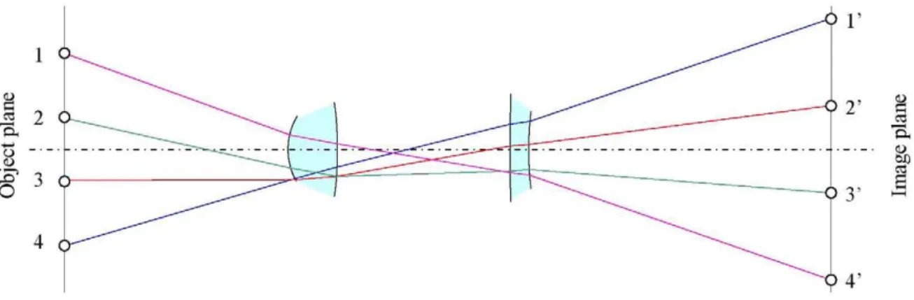
The remaining parts of the Gaussian calculated curves are deleted (Fig. 3). In this situation, each one of the 4 rays (or their symmetric counterparts) crosses 2 of the 8 edges of the 4 curves A, B, C and D. The 4 color dots at the down edges of the curves indicate the rays passing through them. There is at least one ray (the blue ray in the case of Fig. 3) with a single down edge point. If this were not the case, then we can select another 4 rays for a smaller initial portion of curves A,B, CandD.
Fig. 3. Minimizing near axis parts.
TO' 8- o
'
es o ft 5'
Objec
t plan
e
Objec
t plan
e
Objec
t plan
e
Objec
t plan
e
Imag
e plan
e
Imag
e plan
e
Imag
e plan
e
Imag
e plan
For instance, the rays reaching point 4' downwards the blue ray of Fig. 3 can be traced back through the surfaces B, C and D as shown in Fig. 4.a. These rays should come from point 1. Consequently we can calculate the red portion of curve A shown in Fig. 4.a. Once this new portion has been calculated, a new fan of design rays is in the same situation as before. In this case, this is the fan of rays linking points 3 and 3'. The rays issuing from 3 can be traced through the portion of curve A just calculated. The rays of 3' can be traced back through the curves C and D. Now we can calculate a new portion of surface B by the generalized Cartesian oval calculation. This procedure can be repeated to calculate more portions of the curves. The order at which each curve is progressed is not necessarily the same at each SMS iteration. Note that since this case is symmetric, every time we calculate a new portion of a lens, its symmetric counterpart is also calculated.
As in the generalized Cartesian oval calculation, the SMS extension procedure may give curves which do not represent optical systems, although they fulfil the equality of optical path lengths between corresponding points. In these cases, new initial conditions must be explored to find a feasible solution.
s
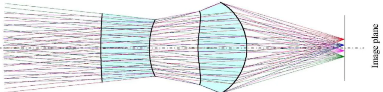
Fig. 5. 4-surfaces SMS design for the incoming bundles ±2° and ±6°. Focal length 8.59 mm. f/1.496. Refractive index 1.5.
Fig. 5 shows a 4-surfaces SMS design formed by 2 lenses whose initial conditions establishes the same thickness for them as well as for the air space between them. This design focuses sharply the bundle of incoming parallel rays with directions ±2 deg and ±6 deg. These 4 bundles are imaged in the points ±0.3mm and ±0.9 mm around the axis
3. RESULTS
Let's 8 be the angle between the axis and a ray. We are going to compare several aplanatic designs with equivalent SMS designs. In both cases we assume the object points to be at the infinity. To evaluate the imaging quality of a design we are going to plot the function % giving the RMS spot radius of an incoming bundle of parallel rays with direction given by 8. For the evaluation of the function a(8) we are going to consider only rays contained in the design plane, since the designs considered in this paper are done in a plane (2D geometry). Consequently an SMS design of N surfaces will get 0(80=0 for N design directions 0¡, (we are assuming that the contribution of the initial parts of the four-surfaces SMS design, which is not theoretically perfect, is negligible) i.e.
o(0)
A(6)Y\{e-e
i)
i=\
(2)
As shown in ref [15], .4(8) is an arbitrary analytic function of 8 which, in a first approximation can be considered a constant function of 8 (although the value of this constant varies with different designs), i.e.,
<T(0):
AU(0-0
t)
i=\(3)
- 4 - 2 0 2 4
incidence angle (deg)
Fig. 6. RMS spot radius in microns of a 3-surfaces SMS design for perfect imaging of incoming rays in directions ±3° and 0°. Refractive index at the image side is 1.5. The red dashed curve is the absolute value of the polynomial
approximating the RMS spot radius (<r(9))
Fig. 7 shows a(0) for a two-surfaces SMS design. This figure also shows the comparison with the aplanatic case which can be seen as an SMS case whose 2 incoming design directions tend to the axial direction (0¡—>0 deg). The value of the constant^ results to be quite similar in the three cases compared in the figure.
-4 -2 0
incidence angle (deg)
Fig. 7. RMS spot radius in microns of several lenses with focal length 14.32mm andf/1.576. Two of the lenses are 2-surfaces SMS designs for perfect imaging of incoming rays in directions ±1 and ±2 deg respectively. The ±2 deg lens is shown in Fig. 1. The third lens is aplanatic
For a given maximum spot radius, it is clear that there is an SMS design with a wider range of incidence angles (i.e., a wider field of view FOV). This is shown in Fig. 8. For the case of single lens (two surfaces) we can approximately say that for the same spot radius upper bound, the FOV angular area of the SMS design is twice bigger than the aplanatic design with the same f-number and the same focal length.
constant ripple maximizes the angular field of view for a given maximum spot radius. The design corresponding to Fig. 9 is done for maximizing the field of view with spot radius smaller that 1 |am. Fig. 10 shows the approximated RMS spot radius of a four-surface SMS design whose 4 design directions are tending to 2 directions: ±4° , i.e., it is a first order aplanatic design for two off-axis directions (we call it "biaplanatic"). This curved is compared with the previous four surfaces ones.
=3 O
0 4 8 field of view diameter (deg)
Fig. 8 Maximum spot radius vs the FOV diameter for aplanatic lenses vs. general SMS lenses. The FOV diameter of an aplanatic lens is approximately V2 times smaller that that of the equivalent SMS lens.
1.5
Ü
8.
0.52n order aplanatic
SMS ±2° and ±6°
-10 - 6 - 4 - 2 0 2 4
incidence angle (deg)
10
Fig. 9. RMS spot radius in microns of 2 lenses with focal length 8.59mm and f/1.496. One of the lenses, which is shown in Fig. 5, is a 4-surfaces SMS design for perfect imaging of incoming rays in directions ±2 and ±6 deg. The other lens is second order aplanatic case.
i 1.5
Ü
s.
1 ~
0.5
0
-10 -8
-
4
-
2
0
2
4
incidence angle (deg)
8 10
Fig. 10. RMS spot radius in microns of 2 lenses with focal length 8.59mm and f/1.496. One of the lenses, which is shown in Fig. 5, is a 4-surfaces SMS design for perfect imaging of incoming rays in directions ±2 and ±6 deg. The other lens is second order aplanatic case.
4. CONCLUSIONS
We have shown a new design strategy for imaging applications of the SMS method, in which we choose as many couples of input and output bundles as surfaces of the optical system to be designed. The SMS method ensures that the input and output bundles become fully coupled by the optical system. In the particular examples shown the input bundles are sets of parallel rays with directions 0¡ and the output bundles are focal points. Once a maximum spot radius in the field is fixed, the SMS design results in a wider FOV (the FOV diameter of the SMS design is 1.41 times that of the equivalent aplanatic designs for the two-surface design and more than twice in the four-surface design). We have also seen that aplanatic designs can be viewed as particular cases of SMS designs.
5. ACKNOWLEDGEMENT
The authors thank the Spanish Ministries MCEI (Consolider program CSD2008-00066, DEFFIO: TEC2008-03773), MITYC (OSV: TSI-02303-2008-52), and the Madrid Regional Government (LED-TV: 130/2008 TIC, ABL: PIE/466/2009, F3: PIE/469/2009 and CAM/UPM-145/Q060910-103) for the support given in the preparation of the present work. The authors from the Universidad Politécnica de Madrid also thank Optical Research Associates for the educational license of LightTools software.
[i] [2] [3] [4]
[5]
[6] [7]
REFERENCES
R. Kingslake, Lens Design Fundamentals (Academic, New York, 1978). W. J. Smith, Modern Optical Engineering, 3rd ed. (McGraw-Hill, 2000). R. E. Fisher and B. Tadic-Galeb, Optical System Design (McGraw-Hill, 2000).
A. E. Conrady, Applied Optics and Optical Design, Part 1, New edition 1992 (Oxford University Press and Dover Publications, 1929).
G. G. Slyusarev, in Aberration and Optical Design Theory, pp. 499-502, Adam Hilger, Techno House, Bristol (1984).
[8]
[9] [10]
K. Schwarzschild, Astronomische Mittheilungen der Koniglichen Sternwarte zu Gottingen 10, 3 (1905), Reprinted: Selected Papers on Astronomical Optics, SPIE Milestone Ser. 73, 3 (1993).
D. Lynden-Bell, "Exact Optics: A Unification of Optical Telescope Design." MNRAS 334. 787-796 (2002)
R. V. Willstrop, D. Lynden-Bell, "Exact Optics — II. Exploration of Designs On- and Off-Axis." MNRAS 342.
33-49 (2003).
[11] P. Benítez and J. C. Miñano, "Ultra high-numerical-aperture imaging concentrator," J. Opt. Soc. Am. A 14,
1988-1997 (1988-1997) http://www.opticsinfobase.org/abstract.cfm7URHosaa-14-8-1988
[12] N. Shatz and J. Bortz, "Optimized image-forming cemented-doublet concentrator," Proc. SPIE, v. 5942, 59420G
(2005)
G. Schulz, Higher order aplanatism, Opt. Commun. 41 (1982), pp. 315-319
G. Schulz, Aspheric surfaces, In: E. Wolf, (Ed.), Progress in Optics, 25, 1988, pp. 349-415
F. Muñoz. Doctoral Thesis "Sistemas ópticos avanzados de gran compactibilidad con aplicaciones en formación de imagen y en iluminación" 2004 http://www
-app.etsit.upm.es/tesis_etsit/documentos_biblioteca/masinformacion.php?sgt=TESIS-04-030
J. C. Miñano and J. C. González, "New method of design of nonimaging concentrators," Appl. Opt. 31, 3051-3060 (1992) http://www.opticsinfobase.org/abstract.cfm?URI=ao-31-16-3051
J. C. Miñano, P. Benítez, and J. C. González, "RX: a nonimaging concentrator," Appl. Opt. 34, 2226-2235 (1995)
http://www.opticsinfobase.org/abstract. cfm?URI=ao-34-13-2226
J. C. Miñano, J. C. González, and P. Benítez, "A high-gain, compact, nonimaging concentrator: RXI," Appl. Opt. 34, 7850-7856 (1995) http://www.opticsinfobase.org/abstract.cfm?URI=ao-34-34-7850
R. Winston, J.C. Miñano, P. Benítez, Nonimaging Optics, (Academic Press, New York, 2005)
P. Benítez, J.C. Miñano, J. Bien, R. Mohedano, J. Chaves, O. Dross, M. Hernández, J. Alvarez, W. Falicoff. "SMS Design Method in 3D Geometry: Examples and Applications," Proc. SPIE 5185, 18-29 (2003).
J. Chaves, Introduction to Nonimaging Optics, (CRC Press, Boca Ratón, 2008).
[13] [14] [15]
[16]
[17]
[18]
[19] [20]