TELEOPERATING A MOBILE MANIPULATOR USING A
UAV CAMERA WITHOUT ROBOT SELF-OCCLUSIONS
Josep-Arnau Claret
Institute of Industrial and Control Engineering, BarcelonaTECH, [email protected]
Luis Basa˜nez
Institute of Industrial and Control Engineering, BarcelonaTECH, [email protected]
Abstract
The paper presents a novel teleoperation system that allows the simultaneous command of a mo-bile manipulator and a free flying camera, im-plemented using a UAV, from which the opera-tor can moniopera-tor the task execution in real-time. A novel use of the kinematic redundancy is pre-sented to prevent the robot parts from occluding the end-effector to the operator view. Following an obstacle avoidance approach, an input is fed to the null space that keeps the robot links away from the end-effector in the image plane as a sec-ondary task. Simulations and the implementation in a real setup show the goodness of the proposed approach.
Keywords: Mobile manipulation, UAV, teleop-eration, redundancy, obstacle avoidance.
1
INTRODUCTION
Teleoperation has been one of the main robotics fields since its inception [6, 11]. One of the key aspects during a teleoperation task is the quality of the view the operator has of the scene [12, 2]. In particular, one aspect often ignored, but which can greatly affect the teleoperation of a robot, is the occlusion of the object at the TCP of the robot that is being commanded by the operator.
Occlusions of the mobile manipulator (MM) TCP can be due to obstacles in the scenario, but also to the robot itself, that is, its links and the platform: the different robot parts can be in a configuration such that they are located between the camera and the TCP, making the visibility of the com-manded object more difficult, thus increasing the workload on the user, and degrading the overall performance of the teleoperation.
Redundancy allows robots to accomplish the main task and fulfill secondary tasks. The null space is a mean to achieve this. It has been used for several secondary tasks: multiple end-effector control [1], singularity [10] and object collision avoidance [8], joint constraints [9], manipulability optimization [13], emotion conveyance to users [3],etc.
a
c
p
r
p
2
p
1
p
0
L
2
L
1
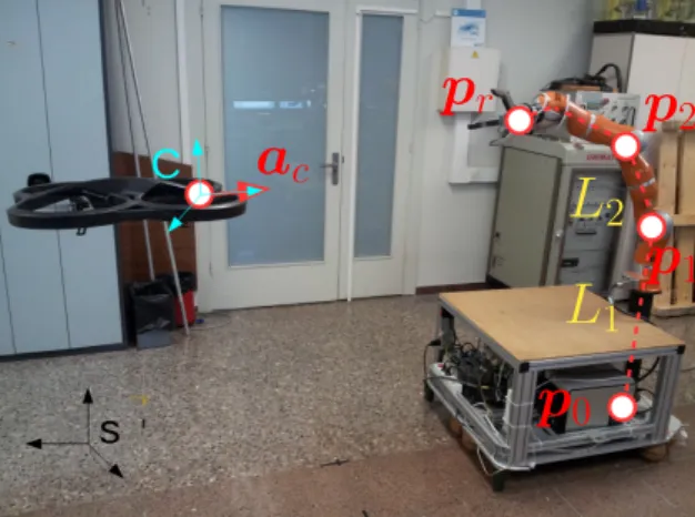
Figure 1: The BMM-I and the free-flying camera.
1.1 CONTRIBUTION
With the idea to free the user from the explicit teleoperation of the robot so that he/she can focus on the object being teleoperated, a need arises to improve as much as possible the view of the object. In order to do so, this paper introduces, to the authors knowledge, the first use of the robot null space to prevent the object attached to the TCP from being occluded by its own body and links.
The presented method, the Object Best View Function (OBVF), has been validated in simula-tions and implemented in a real setup. The solu-tion is presented in a teleoperasolu-tion system previ-ously presented by the authors [4] consisting of the BMM-I (a MM with an omnidirectional platform and a 7 Degrees of Freedom -DOFs- manipulator), an Unmanned Aerial Vehicle (UAV) and a haptic device (Fig. 1). The operator commands the robot TCP using the haptic while getting visual feed-back from the scenario through a camera mounted on the UAV, which allows the camera to track the MM without an explicit operator command, pre-venting the robot from leaving the camera field of view, and easing the teleoperation. The results show the goodness of the proposed solution.
2
PROPOSED SOLUTION
One of the leading aspects to address the afore-mentioned problem is its similarity with the ob-stacle avoidance problem, which goal is to move the robot from an initial to a final configuration in a scenario filled with objects with which the robot can collide. The challenge is to find a feasible tra-jectory or direction of movement that guarantees that the path or the next step is free of collisions.
The force field formulation [7] assigns to each ob-ject a potential field that generates a repulsive force between the object and the robot. A re-sultant force is the result of the influence of all the objects in the scene, which can be input to the robot through its null space and execute the avoidance task with low priority. The main differ-ence with the classical obstacle avoidance problem is that in the OBVF the resultant force generated by the obstacles (the parts of the robot) has to be applied to the robot link itself, since the robot point that is intended to stay away from the ob-stacles is the robot TCP, which already has a tra-jectory to track as the higher priority task.
The proposed solution thus follows the next ideas:
To use the MM null space to avoid robot self-occlusions as a secondary task.
To pose the problem as a collision avoidance task between the robot TCP and particular parts of the robot.
To evaluate the proximity between the TCP and the robot links projected in the image plane. By measuring the distance in the im-age plane between the projected TCP and the links of the robot, the operator point of view is naturally taken into account.
To address the OBVF, anescape velocity (the re-pulsive force in the force field formulation) is gen-erated to further be applied to the point of the robot where the axis of joints 3 and 4 intersect. The desired velocity input is designed to contain the information of the distance of all the links that may occlude the robot TCP and give more impor-tance to the closest links because those are the links more likely to occlude the TCP.
Consider the pointsp0,p1,p2andprof the mobile
manipulator, expressed in the world reference, s, such that each pointpi =pix piy piz
T
∈ R3; and the homogeneous transformation matrixTc
s ∈ SE(3) from the world frame to the camera frame,
c, with the origin pcs ∈ R3 and the orientation described by the rotation matrixRcs∈SO(3). Let
ac denote the unit vector over the optical axis of
the camera pointing towards the robot (Fig. 1).
The OBVF is activated when any p1orp2,
with-out its Z coordinate, is in front ofprseen from the
camera, that is, the coordinate systemcorgin. Let piXY =
Note that the task activation and deactivation can lead to discontinuities; this is addressed below.
When the OBVF is activated, the next step is to change the points reference frame from the world to the camera: ri = (Tsc)
that projects a point in the camera frame r = [rx ry rz]
T
∈R3to a pointc∈
R2in the image plane, considering apinhole camera model as
c= c2ph(r, fc) = fc
rz
rx ry
T
wherefc is the focal length of the camera.
Let’s also define the function ph2c(c, z, fc) that
converts a projected point c = [cx cy]T ∈ R2 in the image plane at the distance fc into its 3D
unprojected pointr∈R3at a distancez with
r= ph2c(c, z, fc) =
The next step is to compute the force exerted on each link of the mobile manipulator. The consid-ered links can be seen in Fig. 1 as L1and L2. L1
is the link defined by the pointsp0 andp1, while
L2 is the link defined by the pointsp1 andp2.
Our interest is to compute the point r∗i ∈R3, in
every linki, such that its projection in the image plane c∗i is closest to the projection of the robot TCP also in the image plane,cr. Givenλi∈[0,1]
any pointrLi in the linkLi can be expressed as
rLi=ri−1+λi(ri−ri−1) =ri−1+λini (2)
withi∈ {1,2}.
This is equivalent to solve:
λ∗i = arg min
λi
kc2ph(ri−1+λini, fc)−c2ph(rr, fc)k
(3) Eq. 3 is also equivalent to obtain the valueλ∗i that minimizes the previous squared distance, which can be obtained analytically (see Appendix). The solutionsλ∗1 andλ∗2 of the minimization problems must lie in [0,1]. Otherwise, points in the same line but outside the link would be taken into ac-count. Once λ∗1 and λ∗2 are obtained, the
In order to determine the repulsive force fi from
the robot TCP to each link both its modulus and its direction need to be computed. The force di-rection can be expressed as the unit vector ui =
(p∗i−pr)/kp∗i−prk with p∗i =Tscr∗i. Although the
force direction points from the TCP to the point in the link, it will ultimately be the link which will be moved away from the TCP.
The modulus of the force, ki, has to be inversely proportional to the distance between the TCP and the link in the image plane, so as to give the tele-operator a sense of coherency between the exerted force and the proximity of the object occlusion. The distance between the TCP and the link in the image plane is straightforward to compute:
di=kc2ph(ri, fc)−c2ph(rr, fc)k.
In order to compute the modulus of the force, a maximum value kF
i of the force can be set when
the distance is smaller than a certain value, dm i .
For distances greater than dMi the modulus can be set to zero,i.e.,ki = 0. The interval [dmi , dMi ] is selected such that a smoothing transition for the force modulus between [0, kiF] can be imple-mented. ki can be written similar as in [9]:
ki=
Finally the force for each linkLican be computed as fi = kiui, which can be interpreted as the
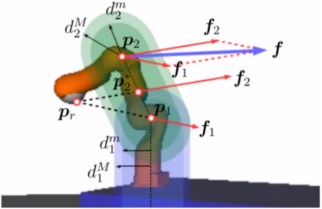
velocity imposed to the corresponding point of the link which prevents it from getting close to the TCP in the image plane. Fig. 2 graphically depicts the elements needed to compute eachfi. The final
forcef is the sum of f1 andf2. This ensures the
continuity and smoothness of the force vector as bothfiare continuous and calculated using Eq. 4.
As stated above, the modulus of the force needs to change in a continuous way also w.r.t. the OBVF activation/deactivation. Otherwise, in a situation where the robot tip would be close to a link in the image plane, but still in front of it, if, due to the user command, the tip of the robot got behind a link (making a si > 0 in Eq. 1) the force would suddenly trigger a discontinuity in the joints.
To address this, a threshold sF has been defined for Eq. 1. This threshold sets up a transition zone where f continuously changes from zero to its appropriate value. This strategy can be im-plemented using a parameter kF for determining
d
m2Figure 2: Exerted forces on the links by the prox-imity of the TCP. The TCP lies outside the area where the forcesf1orf2are generated, which has
been presented this way for ease of visualization.
f =kF(f1+f2), with
The computed f can now to be fed to the null space. But the application point needs to be se-lected. In order to solve the problem of having to switch between several points, which would pro-duce discontinuities and lead to instabilities dur-ing the teleoperation task, the application point has been set to p2. Moreover, discontinuities on
its derivative are also avoided with this choice.
Once the point to apply thef has been chosen, the robot Jacobian at this pointJp2can be computed.
It would be tempting to obtain the joint velocities to feed the null space algorithm by trying to find the appropriate ˙qthat solves the task
f =Jp2q˙.
But note that, since this algorithm attempts to in-crease the distance between the end-effector and the links in the image plane, it doesn’t matter what happens to the distance in the Cartesian space, provided that, when projected in the image plane, it ultimately increases. This means that it is not needed that the closest link of the robot from the end-effector follows the direction pointed by the force f, which implies a three-DOFs task. It is only needed that it does so in the image plane, thus imposing a two-DOFs task.
ma-0 0.5 1 1.5 2 2.5 3 0
1
s
(a)
0 0.5 1 1.5 2 2.5 3 0
0.1
s
(b)
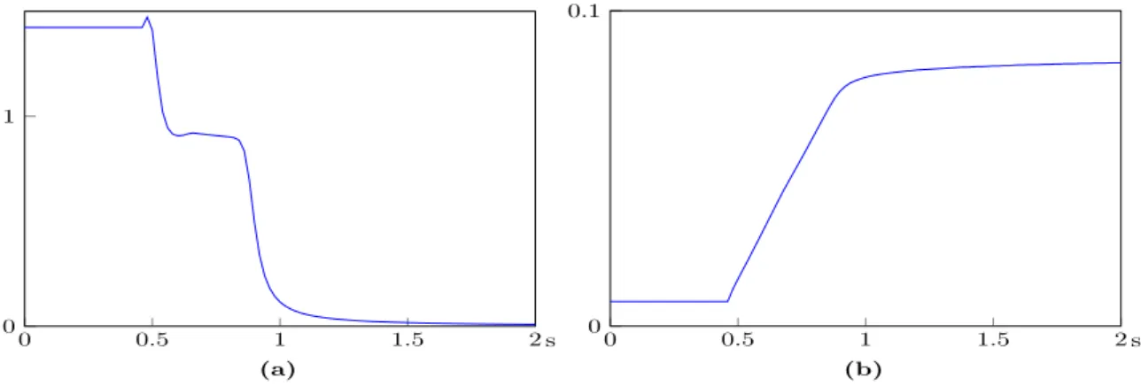
Figure 3: OBVF simulation 1: a) modulus of the force f when the OBVF is active; b) minimum distances betweend1andd2,i.e., min(d1, d2), with the OBVF active (blue) and not active (red).
Figure 4: Simulation 1 without activation. Images follows from left to right.
Figure 5: Simulation 1 with activation. Images follows from left to right.
trices can be defined for this purpose as
PXYJ =
1 0 0 0 0 0
0 1 0 0 0 0
PXYF =
1 0 0 0 1 0
and the OBVF ˙q can be obtained from
fc=PXYF (R c s)
T
f =PXYJ M Jp2q˙=Jcq˙
withfc beingf projected in the image plane;Jc,
the Jacobian of pointp2 in the image plane; and
M= "
(Rc s)
T
0 0 (Rc s)
T
#
a matrix that rotates the vectors of the Jacobian so that they are referenced in the camera frame.
Now the task can be fed as a lower priority task:
˙
q=J1+x˙1+ (JcN1) +
fc−JcJ1+x˙1
.
with task 1 as the end-effector pose tracking.
fc dm
1 dM1 kF1 d
m
2 dM2 kF2 sF
1.0 0.10 0.15 1.5 0.05 0.10 1.0 0.1
Table 1: Simulation parameters.
3
SIMULATION RESULTS
A set of simulations has been run to assess the proposed algorithm. Table 1 shows the simulation values. dm
1 , dM1 , dm2 and dM2 are distances in m:
higher values would imply that the effect of the TCP on the links would be exerted from further distances. kF1 andkF2 have been chosen after ex-perimentation so that the effect of the TCP on the links would be smooth, andsF = 0.1 corresponds to an angle of 84◦, which means that the OBVF activation / deactivation zone corresponds to 6◦.
The mobile manipulator used in this work, the Barcelona Mobile Manipulator 1 (BMM-I), is an omnidirectional mobile platform with a 7 DOFs industrial serial robot [5] (Fig. 1). The platform has 3 DOFs: 2 independent translations in the plane and 1 rotation around its vertical axis and so the system has a total number of 10 DOFs.
In the envisioned teleoperation system, a Parrot AR.Drone is used as the free flying camera (Fig. 1, left side). In order to evaluate the OBVF, an ideal scenario has been set: a UAV perfectly hovering, mimicked by a fixed camera, thus isolating the performance of the OBVF from the UAV motions and easing its evaluation.
The OBVF has been implemented as a secondary task through the null space of the first task. The first task is the command of the TCP by the op-erator using a haptic device as explained in [4].
3.1 SIMULATION 1
0 1 2 3 4 5 6 0
1
s
(a)
0 1 2 3 4 5 6 0
0.1
s
(b)
Figure 6: OBVF simulation 2: a) modulus of the forcef when the OBVF is active; b) minimum of the distancesd1 andd2 with the OBVF active (blue) and not active (red).
Figure 7: Simulation 2 without activation. Images follows from left to right and top to bottom.
Figure 8: Simulation 2 with activation. Images follows from left to right.
with the arm extended horizontally and such that the TCP be hidden behind the robot from the op-erator perspective. Figs. 4 show the motion with-out the OBVF activated, and it can be clearly seen how the TCP is occluded by the robot. Figs. 5 show the same motion with the OBVF activated: the BMM-I does a self-motion such that it pre-vents the occlusion to occur.
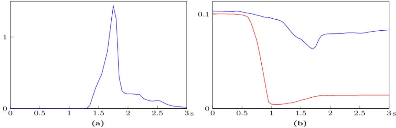
Fig. 3a shows the modulus of f exerted during the motion, and Fig. 3b, the minimum distances
d1andd2when the OBVF is active and not. kfk
can be seen to increase when the distance between the TCP and the links decreases, peaking at the lowest distance (blue line), and stabilizing. It can also be seen how the distance remains far from zero when the OBVF is active, while it becomes almost zero otherwise.
Link with the simulation video: Simulation 1.
3.2 SIMULATION 2
In this simulation, the operator commands the TCP to move from right to left parallel to the image plane and such that, at the beginning of the motion, the TCP is at the back of the plat-form w.r.t. the camera. This required motion is solved by the inverse kinematics by first execut-ing a general rotation motion around the Z axis of the platform to locate the TCP at the front of the motion, as if it was to pull the platform to the left side of the scenario. The particular motion of this simulation has been set such that the rota-tion moves the TCP behind the robot becoming occluded by the robot. To prevent the mentioned occlusion, the OBVF has been activated.
Figs. 7 and 8 show the motion of the simulation without and with the OBVF activated. When the OBVF is not active, an occlusion occurs during the teleoperation (Fig. 7, third image), which does not happen when the task is active.
Fig. 6b shows the minimum distances d1 and d2
0 0.5 1 1.5 2 0
1
s
(a)
0 0.5 1 1.5 2 0
0.1
s
(b)
Figure 9: OBVF simulation 3: a) modulus of the forcef; b) minimum of the distancesd1 andd2.
Figure 10: Simulation 3. Images follows from left to right.
Fig. 6a shows the modulus of f, which increases at the beginning as soon as the distance starts to diminish, peaks and stabilizes.
Differently from simulation 1, the force exerted does not become zero after it peaks (Fig. 6a) be-cause the commanded trajectory is such that its TCP is always pushed against its links, so that the forcef is neverallowed to diminish. On the con-trary, in simulation 1 the desired TCP trajectory is such that the OBVF exerts a force that moves the robot links fully away from the TCP, making then forcef equal to zero.
Link with the simulation video: Simulation 2.
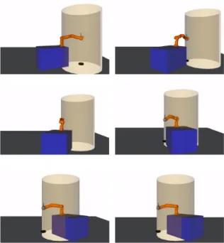
3.3 SIMULATION 3
This simulation consists in the escape of the BMM-I from a configuration in which, from the operator point of view, the TCP is very close to the links (Figs. 10, left image). Note that the links 2 and 3 are much closer to the TCP in the image plane than the first link. Suddenly, the OBVF gets activated at time 0.5 s. Being the scenario such that the links 2 and 3 are occluding the robot TCP, it is expected that the influence of the force f2will be stronger thanf1, and so the robot joints
will rotate to move the links 2 and 3 away from the TCP. Figs. 10 show the evolution of the robot configuration once the OBVF is activated, show-ing the expected behavior and freeshow-ing the TCP
from the occlusion.
Figs. 9 show the modulus of the exerted force f and the minimum distance between the TCP and the robot links, which increases until 0.08 m.
Note the shape of the force in the left image in Figs. 9: at the beginning, thef is 1.5 N, but since the OBVF is not active until the 0.5 s, it does not generate a motion on the robot nor an increase of the distance between the TCP and the links. Once the OBVF is active, the distance starts to increase and the force, to decrease. At this point, a high negative slope of the force is followed by a con-stant force at around 0.9 N during 0.3 s, followed by a high negative slope until the force becomes almost null. Thischair shape is explained by con-sidering that at the beginningf contains both the influence off1 andf2 and that, since the TCP is
very close to the link 2, the contribution off2 is
maximum,i.e.,f2=k2u2. Once the OBVF gets
active the force starts to move the links 1 and 2 away from the TCP. During the first high negative slope, f2 is constant, since the distance between
the TCP and the link 2 is very small (d2< dmi in
Eq. 5), butf1is decreasing (d1∈[dm1, d
M
1 ]). Once
f1becomes null (d1> dM1 ), the only contribution
tof isf2so that for 0.3 s the force modulus is
con-stant and the distance between the TCP and the robot links increases (in particular with link 2). Finally,d2 becomes such thatf2 starts to
dimin-ish (d2∈[dm2, dM2 ]) and becomes null (d2> dM2 ).
4
EXPERIMENTAL
VALIDATION
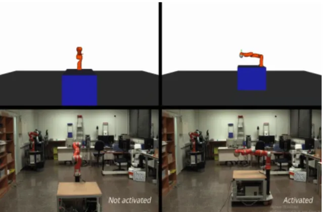
Two experiments have been executed to test the OBVF in a real setup, corresponding to the Simu-lations 1 and 2. The videos can be found in OBVF simulation 1 and OBVF simulation 2. A snapshot of the first is shown in Fig. 11.
Figure 11: Snapshot of the simulation 1 video.
figures correspond to motions without the OBVF activation, and the right figures, with the acti-vation. The top ones correspond to the simulated motions, and the bottom figures, in the real setup.
5
CONCLUSIONS
The OBVF has been presented, developed and tested in different scenarios. In all cases the pro-posed solution has prevented the TCP from being occluded by the robot parts. This work shows that it is possible to teleoperate a mobile manipulator while using the robot null space to prevent robot self-occlusions of the object, improving the oper-ator view of the object, and thus the performance of the teleoperation.
Future work will include the generalization to mo-bile manipulators with any number of joints, and experiments with a free-flying camera.
Appendix
Given a linkLdefined by two pointsrM,rm∈R3 such that any point rL ∈ R3 in the link is rL =
rm+λn withλ∈[0,1] and n=rM −rm, and
given a point r ∈ R3, the aim is to find the λ∗ that minimizes the distance D of the projection in the image plane betweenLandrconsidering a pinhole camera model.
The solution can be analytically computed since
λ∗ = arg min
λ
(D) = arg min
λ
D2
.
Differentiat-ingD2w.r.t. λ, and equating to zero,λ∗=A/B:
A= (rmx)2rznz−rxmrzmrxnz−rmx rmz rznx
+ (rym)2rznz−rymrzmrynz−rmy rmz rzny
+ (rzm)2rxnx+ (rmz)
2r
yny,
B =rmx rx(nz)2−rxmrznxnz+rymry(nz)2
−rymrznynz−rzmrxnxnz−rzmrynynz
+rzmrz(nx)2+rmz rz(ny)2.
Acknowledgement
*This work was partially supported by the Spanish Government through the project DPI2016-80077-R.
References
[1] Baerlocher, P. and Boulic, R., (1998) Task-priority formulations for the kinematic con-trol of highly redundant articulated struc-tures, Intelligent Robots and Systems, 1998. Proceedings., 1998 IEEE/RSJ International Conference on, vol 1, pp 323-329.
[2] Chen, J. Y. C., Haas, E. C. and Barnes, M. J., (2007) Human Performance Issues and User Interface Design for Teleoperated Robots,
IEEE Transactions on Systems, Man, and Cybernetics, Part C (Applications and Re-views), vol 37, num 6, pp 1231-1245.
[3] Claret, J. A., Venture, G., and Basa˜nez, L., (2017) Exploiting the Robot Kinematic Re-dundancy for Emotion Conveyance to Hu-mans as a Lower Priority Task,International Journal of Social Robotics, vol 9, num 2, pp 277-292.
[4] Claret, J. A., Zaplana, I. and Basa˜nez, L., (2016) Teleoperating a mobile manipulator and a free-flying camera from a single haptic device, 2016 IEEE International Symposium on Safety, Security, and Rescue Robotics (SSRR), pp 291-296.
[5] Clos, D. and Mart´ınez, J., (2007) Plataforma M`obil amb Rodes Esf`eriques per al Robot ”Lightweight Robot 4” de Kuka Roboter, In-stitute of Industrial and Control Engineering - Technical University of Catalonia.
[6] Goertz, R. C., (1952) A force reflecting po-sitional servo mechanism,Nucleonics, vol 10, part II, pp 43-45.
[7] Khatib, O., (1986) Real-Time Obstacle Avoidance for Manipulators and Mobile Robots, The International Journal of Robotics Research, vol 5, num 1, pp 90-98.
[8] Maciejewski, A.and Klein C., (1985) Obstacle Avoidance for Kinematically Redundant Ma-nipulators in Dynamically Varying Environ-ments,The International Journal of Robotics Research, vol 4, num 3, pp 109-117.
[9] Mansard, N., Khatib, O. and Kheddar, A., (2009) A Unified Approach to Integrate Uni-lateral Constraints in the Stack of Tasks,
[10] Nemec, B. and Zlajpah, L., (2000) Null Space Velocity Control with Dynamically Consis-tent Pseudo-inverse,Robotica, vol 18, num 5, pp 513-518.
[11] Nu˜no, E. and Basa˜nez, L., (2009) Nonlin-ear Bilateral Teleoperation: Stability Anal-ysis,2009 IEEE International Conference on Robotics and Automation, pp 3718-3723.
[12] Shiroma, N., Sato, N., Chiu, Y. and Mat-suno, F., (2004) Study on effective camera images for mobile robot teleoperation, RO-MAN 2004. 13th IEEE International Work-shop on Robot and Human Interactive Com-munication, pp 107-112.
[13] Yoshikawa, T., (1985) Dynamic manipulabil-ity of robot manipulators, Proceedings. 1985 IEEE International Conference on Robotics and Automation, vol 2, pp 1033-1038.