TítuloFrequency response of IPMC actuators: physical characterization and identification for control
8
0
0
Texto completo
(2) of gold electrodes, and the tip deflection was measured by means of a laser distance meter. It should be remarked that the final objective of this work is the construction of a flexible microrobot based on this technology to be able to swim in a fluid with similar properties of human blood. The remainder of this paper is organized as follows. Section 2 provides more details of IPMC actuators concerning technology and physical models. Section 3 describes the experiments carried out to obtain the frequency responses of the actuators. Physics characterization and system identification for control applications are addressed in Sections 4 and 5, respectively. Section 6 draws the main conclusions of this paper and future work.. 2. Figure 1: Ion motion when a potential difference is applied. Internal forces are generated inside the polymer, forcing the bending. low to understand how parameters affect to the performance and compare with black-box models. The electrode surface resistance has been included in the model through a lumped electrical model.. IPMC ACTUATORS. This section briefly reviews the current state-ofthe art of IPMC manufacturing technology and physics-based models, namely, impedance and actuation models. 2.1. 2.2.1. It is a must to start showing the basic electrostatic equations:. TECHNOLOGY DESCRIPTION. E = −∇ϕ. IPMC units are usually manufactured using Nafion, a thin ion-exchange layer based on a perfluorinated ionomer membrane in a hydrated state with water as solvent, plated with platinum and establishing a couple of electrodes on both surfaces. The ion-exchange layer is neutralized with Na+ counteriones in order to balance the electric charge of the anions attached to the ionomer.. D = κe E ∂D = F (C + − C − ) ∂x. (1). where ϕ, D, E, κe , F , C + , and C − are the electric potential field in the polymer, electric displacement, electric field, electric permittivity, Faraday’s number, and the cation and anion concentration, respectively. The ion-exchange dynamic can be described using continuity equation:. Likewise, IPMC units can be also manufactured using different types of ionomer membranes, like Flemion, and using different types of counteriones, like Li+ , Rb+ , K+ , Cs+ , Ti+ , Ba+ , with water, ethylene glycol, or glycerol as solvent, and other organic cations for dry IPMC actuators like TBA+ and TMA+ . When a positive voltage is applied in one of the electrodes, an ion migration is produced, moving the hydrated cations and water molecules inside the polymer towards to the opposite surface, as can be seen in Figure 1. This motion will increase the gradient concentration, producing electrostatic and osmotic forces inside the polymer, and forcing the bending as result. 2.2. Governing equations. ∇·J=−. ∂C + ∂t. (2). where J is the ion flux vector inside the polymer and ∇ · J is the divergence. The ion flux J is described as: ) ( C + ∆V C +F ∇ϕ + ∇P + C + v J = −d ∇C + + RT RT (3) where d is the ion diffusivity, R is the gas constant, T is the absolute temperature, P is the pressure, and ∆V is the volumetric change. Combining (1)– (3) and neglecting small terms, a PDE for charge density ρ(x, z, t) is obtained:. PHYSICS BASED MODELS. An impedance and actuation IPMC model are obtained following [1], solving the governing partial differential equation (PDE) in the Laplace domain, and assuming that the induced stress in proportional to the charge density. As commented, both models are useful for design and material characterization, and as showed later, it will al-. ∂ 2 ρ F 2 dC − ∂ρ +d 2 + (1 − C − ∆V )ρ = 0 ∂t ∂x κe RT. (4). Reference axis is defined in the central polymer backbone, being h the distance between the backbone and the electrode layer as shown in Figure. 718.
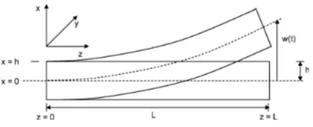
(3) Figure 2: Geometrical definition. tracted from [1].. Imaged ex-. 2. It is assumed that the induced stress is proportional to charge density [7]: σ = α0 ρ. Figure 3: Electrical lumped model of an IPMC unit. Several electrical units can be attached to obtain the global response.. (5). using Laplace transform for ρ(x, z, t), the original PDE (4) becomes into an ODE as shown next: sρ − d. with. 2. ∂ ρ + Kρ = 0 ∂x2. (6). A(s) =. where K = FκedC RT . A symmetrical charge distribution is assumed around x = 0, thus a solution for the charge density can be obtained as:. B(s) =. 2. r1′ A(s) W sW κe γ(s)(s + K) θ(s) = h(sγ(s) + K tanh(γ(s)). −. ρ(x, z, s) = 2c2 (z, s) sinh(β(s)x) (7) √ s+K where β = d , and c2 is a generic function which depends on the boundary conditions. 2.2.2. 2.2.3. (11). Actuation model. Euler-Bernoulli beam theory is considered for linear displacement, therefore, bending moment can be expressed as:. Impedance model. IPMC actuators can be split in several electrical units. Figure 3 shows an electrical lumped model, where expressions relating current and electric potential are given by ∂ϕ± r′ = ± 1 is (z, s) ∂z W. θ(s) 2W + ′ 1 + r2′ θ(s)/W Rp. M = −EI. ∂2w ∂x2. (12). where E is the elastic modulus, I is the second moment of area, and w is the deflection. Solving w with w(0, s) = 0 and w′ (0, s) = 0 as boundary conditions, and considering that induced stress is proportional to charge density, it is possible to obtain an expression to relate tip deflection with the applied voltage as follows:. (8). ∂is (z, s) = −(ip (z, s) + ik (z, s)) (9) ∂z where is , ip and ik denote the surface current on the electrodes, the distributed current through the polymer due to ion motion and the leaking current, respectively. Surface resistance appears due to the platinum electrodes, generating a drop voltage along z and x axes. Resistances r1 = r1′ /W , r2 = r2′ /W and Rp = Rp′ /W represent the impedances for one electrical unit, being r1′ and r2′ the resistance per unit length Ω·m in the electrodes for z and x axes, and Rp′ representing the polymer resistance per unit length.. w(L, s) = V (s) L2 α0 W Kκe (γ(s) − tanh(γ(s))) 2X(s) =− 2EI (γ(s)s + K tanh(γ(s))) 1 + r2′ θ(s)/W (13) H(s) =. where X(s) is given by: X(s) = −. √ √ √ 1 − sech( B(s)L) − tanh( B(s)L) B(s)L B(s)L2 (14). Additionally, it is necessary to couple a mechanical second order system to obtain a reliable model of the IPMC dynamics for the first vibration mode, being accurate enough if the bandwidth is relatively low:. Total current can be expressed as I(s) = i(0, s), therefore, and using an expression for the electric potential regarding the applied voltage, an expression for the global impedance can be obtained as: √ 2 B(s) V (s) √ (10) = Z(s) = I(s) A(s) tanh( B(s)L). G(s) =. 719. ωn s2 + 2ξωn s + ωn2. (15).
(4) The global dynamics of the system is obtained by the product of both transfers function, i.e., M (s) = H(s)G(s). The mechanical model (15) is already a finiteorder model, therefore, global dynamic can be estimated as follows:. (16) M (s) ≈ Hr (s)G(s). 2.2.4. Finite-order actuation model. As can be seen in Figure 4, a third order Taylor series expansion is necessary to match both models. Mismatch appears for lower order expansion. Notice that, since this figure presents tip deflection versus applied voltage, magnitude units are represented in decibels of mm/V.. Both impedance and actuation models are useful to determinate the influence of parameters in performance. In order to compare black-box models obtained by system identification with theoretical IPMC response, it is necessary the simplification of the infinite-order physics-based model√H(s), B(s), which includes non-rational terms of s, tanh(s) or sinh(s). These complex parameters can be reduced into a rational function of s for low frequencies using Taylor series expansion to replace the hyperbolical functions for their relates. Based on the regular parameters values, it can be said that K >> 106 and γ(s) >> 10 for low frequencies. Therefore, next statements can be said as true: tanh(γ(s)) ≈ 1 √ γ(s) ≈ γ = h. 3. 3.1. • a water tank, used as environment; • a laser distance meter, to obtain the tip deflection of a clamped IPMC actuator; • a clamp, which was fabricated by 3D printing technology, using gold electrodes to transmit the voltage from the supplier to the IPMC surface;. where, using statements (17) and Taylor series expansion, functions f (s), g(s) and X(s) can be expressed as: 2. Kκe (γ−1) γs+K. g(s) = 1+. X(s) =. ∑m. (. ). B(s)L. n=0. −. (2n+1)!. ∑m n=0. √. (. ). B(s)L. (. (20) ). B(s)L. 2n+2. • a data acquisition USB board of National Instruments (NI), connected to a computer in which runs LabVIEW, to collect the data;. (19). 2h(γs+K) r2′ γκe s(s+K)+h(γs+K) ( √ √ 2n+2. SET-UP. A scheme of the experimental set-up used in this work to obtain frequency responses of the manufactured IPMC actuators is illustrated in Figure 5. As can be seen, it consists of:. Expression (13) can be approximated by the product of three different rational transfers functions, i.e., H(s) ≈ Hr (s) = f (s)g(s)X(s) (18). α0 W f (s) = − L 2EI. EXPERIMENTS. This section is devoted to the experiments carried out to obtain frequency responses of the IPMC actuators.. (17). K d. (22). 2n ). • an operational amplifier, as power stage to amplify the voltage coming from the data acquisition board.. 2n!. (21). 2n!. Laser refraction coming from glass and water is fixed with LabVIEW through the implementation of corrective factors provided by the laser supplier. The voltmeter and the ammeter are used to measure the voltage and the applied current, respectively, sent to the program in order to collect the data for future researches. As commented, several IPMC samples have been manufactured. All the samples have the same base geometry, with four actuators per sample and every of them with different widths. The pictures of two samples are shown in Figures 6a and 6b, while dimensions for every sample are shown in Table 1. Figures 7a and 7b show real images of. Figure 4: First IPMC vibration mode around 10 Hz. Infinite and finite third order model match for the frequencies of interest.. 720.
(5) (a) IPMC sample pointed by the laser distance meter. Narrower actuator is tested in that case.. Figure 5: Experimental set-up used to experiment with different IPMC actuators.. a sample pointed by the laser during the experiments. Note that some bubbles can be seen between the electrodes and the surface due to water electrolysis when more than 2 V are applied. (b) Zoom of IPMC sample pointed by the laser distance meter. Bubbles in the upper connection appears when more than 2 V are applied, inducing water electrolysis inside the polymer.. Figure 7: Pictures of the experimental set-up. Table 1: Dimensions for one IPMC sample (they are the same for all the samples).. (a) IPMC5 sample (referred to as sample 2 in the experiments).. IPMC actuator Actuator 1 Actuator 2 Actuator 3 Actuator 4. Width (mm) 4.0 2.0 1.0 0.5. Thickness (mm) 0.25 0.25 0.25 0.25. Here, several experimental responses of actuators with the same geometry are shown, each of them belonging to different IPMC samples. As can be seen, there are differences mostly in the gain of the system, even though all them come from the same patch. That promotes robust control techniques for future modelling and control design. Parameter α0 can be shifted to fix the drawback between samples.. (b) IPMC9 sample (referred to as sample 6 in the experiments).. Figure 6: Pictures of two IPMC samples. Images provided by Andres Hunt.. 3.2. Length (mm) 15.0 15.0 15.0 15.0. 4. FREQUENCY ANALYSIS. A total amount of six samples have been tested. Experiments are based in applying sine waves varying the frequency and measuring tip deflection. Frequency spectra is obtained after analysis of the time response, estimating the amplitude and phase difference between the applied sine wave and the first harmonic of the IPMC tip motion. Experimental data are plotted in Figure 8.. PHYSICAL CHARACTERIZATION. This section gives the results obtained for the physical characterization of IPMCs. The fitting process consists of minimizing the error between the experimental data and the response of the theoretical model by using fminsearch and fminbnd MATLAB functions. Initial values (be-. 721.
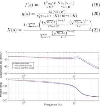
(6) Figure 8: Frequency response of 6 different samples, all of them with the same geometry. Length 15 mm, width 4 mm and thickness 0.25 mm.. Figure 9: Comparison of experimental and physics-based model frequency responses for actuators of sample 1 (widths of 4 mm, 2 mm, 1 mm and 0.5 mm).. Table 2: Initial values of physical parameters T 300 K ξ 0.18 d 3.48 × 10⁻¹¹ m2 /s Ke 5.07 × 10⁻⁷ F/m. E 154 MPa h 0.125 mm C 1068 mol/m3 r2′ 9.99 × 10⁻⁶ Ωm. the samples. Changes in damping, ion diffusivity, or even the appearance of some non linear effects due to the manufacturing process could explain the unmatching between experimental and theoretical responses.. ωn 75.4 rad/s Rp′ 0.37 Ωm2 α0 -40 r1′ 64 Ωm. fore fitting) of key physical parameters are given in Table 2. Only some values are varied in the fitting procedure, most of them limited to the 50% of its initial value; the remainder parameters are fixed. Table 3 shows the values of the key parameters after fitting. Note that α0 allows to fit the gain of the system even if the model is not accurate enough.. Figure 10: Comparison of experimental and physics-based model frequency responses for actuators of sample 2 (widths of 4 mm, 2 mm, 1 mm and 0.5 mm).. The results after fitting for one IPMC sample can be observed in Figure 9. Here the model is fitted to the bigger sample (4 mm width). Experimentally frequency response is influenced by width. Nevertheless, and analysing equation (13) carefully, it is seen that theoretically IPMC does not depend on this variable. A Smaller width will produce a smaller moment generation, therefore, since stiffness decreases also linearly with width, net dynamic should not be affected.. As commented, physics-based model can be used to determinate which parameters affect to the actuator performance. More specifically in that case, the model can be used to determinate which parameter has been modified during the cutting process between actuators of the same sample. For example, as shown in Figure 11, an increment in the value of parameter r2 will decrease the gain of the system. This undesirable effect, together with others, could explain this phenomenon. Nevertheless, this issue will be studied in future works.. The same phenomenon appears in Figure 10 after testing and fitting a second sample. In this case, it is more evident that there is some dependency between the width and tip displacement. All the experiments keep the same results for all. 5 Table 3: Values of physical parameters after fitting d 3.07 × 10⁻¹¹ m2 /s Ke 4.47 × 10⁻⁷ F/m. C 941.94 mol/m3 r2′ 8.81 × 10⁻⁶ Ωm. α0 -155 r1′ 56.44 Ω. IDENTIFICATION FOR CONTROL. This section presents several black-box models identified from the above-mentioned experimental frequency responses for control purposes. In this work, System Identification toolbox of MATLAB. 722.
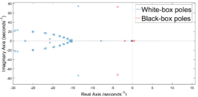
(7) Figure 11: Effect of an increment in parameter r2 on experimental frequency responses for actuators of sample 2 (widths of 4 mm, 2 mm, 1 mm and 0.5 mm).. Figure 12: Comparison of experimental and model frequency responses for actuators of sample 4: model with 4 poles and 1 zero.. was used to obtain the models. At first glance, the global dynamics of the actuators is approximated by a transfer function with 4 poles and 1 zero. The results are represented in Figure 12. However, as can be observed, experimental and model responses do not match perfectly. Mismatch can be seen through s−plane in Figure 13. In that case, the poles of the model are not close enough to those of the physics based model. Therefore, it can be stated that the identified model can fit the resonance point, but it can not match the complete experimental frequency response.. Figure 13: Pole-zero maps of white box (dominant) and the model with 4 poles and 1 zero for actuators of sample 4.. If the number of poles and zeros increases, a better fitting can be obtained, as shown in Figure 14 for a model with 5 poles and 2 zeros. It is possible to obtain the percent of adjustment using ident MATLAB tool. In that case, an adjustment of 92.57% is obtained between model and the experimental data. Poles are shown in Figure 15. Additional black-box models have been used for other samples as shown in Figure 16 for sample 1, ratifying the models with at least 5 poles and 2 zeros should be used for modelling IPMC actuators. In this case, the adjustment between experimental and model responses is of 92.96%.. Figure 14: Comparison of experimental and model frequency responses for actuators of sample 4: model with 5 poles and 2 zeros.. 6. meter.. CONCLUSIONS. In what the characterization of the IPMC actuators is concerned, although chemical manufacturing and cutting method used in this work seems to be good enough for the purpose of this work, it was demonstrated that several physical parameters can differ in different samples obtained of the same IPMC sheet. For the second objective, models with at least 5 poles and 2 zeros were identified.. This paper has analyzed the frequency responses of several IPMC actuators, cut from the same bulk IPMC sheet with a micro laser etching machine, in order to: 1) characterize each actuator, i.e., determine how cutting affects to the parameters of the physical model of this kind of actuators, and 2) identify a model for each actuator for control purposes. The frequency responses were obtained experimentally in LabVIEW by attaching a couple of gold electrodes to each IPMC unit and measuring the tip deflection by means of a laser distance. Our future efforts will focus on three directions: 1) the investigation of new fabrication methods. 723.
(8) [3] Guo-Hua Feng and Ri-Hong Chen. Improved cost-effective fabrication of arbitrarily shaped µIPMC transducers. Journal of Micromechanics and Microengineering, 18(1):015016, 2008. [4] Andres Hunt. Application-Oriented Performance Characterization of the Ionic Polymer Transducers (IPTs). PhD thesis, Tallin University of Technology, 04 2017. [5] J. Liu, Y. Wang, D. Zhao, C. Zhang, H. Chen, and D. Li. Design and fabrication of an IPMC-embedded tube for minimally invasive surgery applications. In Electroactive Polymer Actuators and Devices (EAPAD) 2014, 2014.. Figure 15: Pole-zero maps of white box (dominant) and the model with 5 poles and 2 zeros for actuators of sample 4.. [6] Sia Nemat-Nasser. Micromechanics of actuation of ionic polymer-metal composites. Journal of Applied Physics, 92(5):2899–2915, 2002. [7] Sia Nemat-Nasser and Jiang Yu Li. Electromechanical response of ionic polymermetal composites. Journal of Applied Physics, 87(7):3321–3331, 2000. Figure 16: Comparison of experimental and model frequency responses for actuators of sample 1: model 5 poles and 2 zeros.. [8] Deivid Pugal. Physics Based Model of Ionic Polymer Metal Composite Electromechanical and Mechanoelectrical Transduction. PhD thesis, University of Nevada, 2012.. of IPMC actuator, 2) the design of robust control strategies to obtain a gain and phase range to control the system, and 3) the manufacturing of a small prototype IPMC robot to be able to swim in conditions similar to those found in the human circulatory system.. [9] Mohsen Shahinpoor and Kwang J. Kim. Ionic polymer metal composites: IV Industrial and medical applications. Smart Materials and Structures, 14(1):197, 2005. [10] Tyler Stalbaum, Taeseon Hwang, Sarah Trabia, Qi Shen, Robert Hunt, Zakai Olsen, and Kwang J. Kim. Bioinspired travelling wave generation in soft-robotics using ionic polymer-metal composites. International Journal of Intelligent Robotics and Applications, 1(2):167–179, Jun 2017.. ACKNOWLEDGMENT This work has been supported by the Spanish Ministry of Economy and Competitiveness under the project with reference DPI2016-80547-R.. [11] Shigeki Tsuchitani, Kunitomo Kikuchi, Ippei Shimizu, Tomohisa Taniguchi, and Hirofumi Miki. IPMC actuators fabricated using MEMS technology. In 7th Forum on New Materials - Part A, volume 97 of Advances in Science and Technology, pages 57–60. Trans Tech Publications, 1 2017.. References [1] Z. Chen and X. Tan. A control-oriented and physics-based model for ionic polymer–metal composite actuators. IEEE/ASME Transactions on Mechatronics, 13(5):519–529, Oct 2008. [2] Guo-Hua Feng and Ri-Hong Chen. Universal concept for fabricating arbitrary shaped µIPMC transducers and its application on developing accurately controlled surgical devices. In 2007 2nd IEEE International Conference on Nano/Micro Engineered and Molecular Systems, pages 622–625, 2007.. c 2018 by the authors. ⃝ Submitted for possible open access publication under the terms and conditions of the Creative Commons Attribution CC-BY-NC 3.0 license (http://creativecommons.org/licenses/by-nc/3.0/).. 724.
(9)
Figure


+4

Documento similar
In this paper, we characterize the vanishing of such invariants for a
To see this, note that each edge we paste along corresponds to a cross cut in the unit disk and that the diameter of the cross cut is comparable to its harmonic measure with respect
No obstante, como esta enfermedad afecta a cada persona de manera diferente, no todas las opciones de cuidado y tratamiento pueden ser apropiadas para cada individuo.. La forma
This text discusses the characterization of compact solid-state lasers, as a first approach to the study of the microchip laser concept applied to several rare earth-doped
The availability of small deformable mirrors with large number of actuators and stroke, on one hand, and versatile wavefront sensors (pyramid WFS), on the other, allows the
This chapter provides information necessary to install and use the IPMC712 and IPMC761 modules on your MVME5100 Single Board Computer (SBC).. The IPMC712 and IPMC761 are
Number of actuator modules over the actuators per module. thickness of the support
The hardware abstract layers model the features of the physical components of the system, defining virtual sensors, actuators, motion controllers, etc.. The hardware abstract
