Design and Implementation of a Quasi-Orthogonal
Switching Beam-Former for Triangular Arrays of
Three Radiating Elements
Javier García-Gaseo Trujillo, Alvaro Noval Sánchez de Toca, Ignacio Montesinos Ortego, José Manuel Fernández González, and Manuel Sierra Pérez
Abstract—An innovative switching multi-beam network for triangular arrays of three radiating elements is proposed. This novel network provides three orthogonal beams in a desired ele-vation angle and a fourth one in the broadside steering direction. The network is composed of four-port 3-dB quadrature hybrid power couplers and fixed phase shifters. In this paper, a relation between network components, radiating element distance and beam steering directions is shown. Application of the proposed dissipative network to the triangular cell of three double stacked patches of 1.7 GHz and 60° beamwidth that integrates the in-telligent antenna GEODA with an array distance of 0.56A is exhibited. Measured scattering parameters of the network are compared with both, theoretical and simulated scattering ma-trices, validating the expected behavior. Besides, by combining two complementary single proposed networks, a matrix that supplies six orthogonal beams in a given elevation angle and a seventh one in the broadside steering direction has been built. Moreover, the whole system, dissipative network with GEODA cell array, has been measured in the anechoic chamber of the Radiation Group at Technical University of Madrid, demonstrating a successful performance.
Index Terms—Adaptive arrays, beam steering, multibeam an-tennas, phased arrays.
I. INTRODUCTION
F
ROM the beginning of telemetry, tracking and command (TT&C) systems, mechanical scanning antennas have been employed at ground stations. As it is well known, this technique is not only sensitive to gravity and mechanical failure, but also slow, increasing the total cost of the system and making simultaneous satellite communications infeasible. The use of electronically scanned antenna arrays overcomes these limitations, allowing much faster multi-beam scans without physical antenna rotation [1], [2]. These types of systems that use information from the link environment to set the proper beam shape are called intelligent architectures [3], [4].In order to improve the ground station performance, many studies have been carried out in the field of electronic scan-ning systems, in which large arrays composed of thousand of radiating elements have been considered [5]. Electronic steering technique is based on the control of the relative amplitude and phase of the signal associated with each antenna that composes the whole array. The relative signal can be adjusted by using dig-ital signal processing algorithms, e.g., MUSIC [6] or ESPRIT [7], or placing beam-forming circuits inside the hardware an-tenna, e.g., phase shifters [8] or switched networks [9].
Nowadays, software/hardware hybrid architectures are gaining special interest because of their versatility. Generally, these huge array structures are divided into subarrays based on unitary cells of at least three radiating elements to reduce not only post-processing data time but also its cost [10]—[12]. The unitary cell radiation pattern, the combiner/divider cell circuit and the post-processing data algorithm will define the whole system capabilities. This segmentation may reduce the total number of required active circuits, such as amplifiers or phase shifters [13], decreasing total cost and improving post-pro-cessing data efficiency. Usually, this type of antenna performs a hardware beam steering that selects the willing communi-cation direction area and a signal data processing algorithm that improves the desired signal to interfering signal/noise rates. Therefore, the study of structures that provide multiple beams in different spatial ranges related to each sub-array cell is needed.
The number of radiating elements composing the unitary cell and its distribution state the basic beam scanning shape. A tri-angular cell of three radiating elements is the simplest way to obtain a planar scanner. In this paper, a new multibeam network configuration that provides three orthogonal beams in a desired
6Q elevation angle and an extra one in the broadside steering
net-- T ^ Y
70
„ 60
D> <L>
C O § 40
•I 30 £
I 20 d) m
10
a/b = 0.5; 3 = 104.5° a/b = 0.7; 3 = 110.5° a/b = 1.0; 8 = 120° — a/b = 1.3; p = 130.5°
a/b =1.5; 3 =
138.6°-^ 138.6°-^ " 138.6°-^ 138.6°-^ 138.6°-^ 138.6°-^
^ ^ ^ ^ - S s
0.5 0.6 0.7 0.8 0.9 1 1.1 Array distance d [A]
1.2 1.3 1.4 1.5
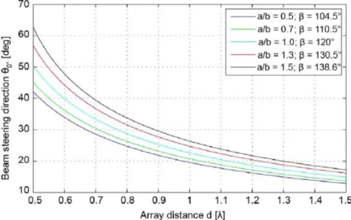
Fig. 1. (Left) Triangular cell of three radiating elements and its orthogonal f^2- Array factor steering direction 0O respect to array distances for different
beams [Azimuth xy-plane]. (Right) Coordinate System. feeding signal relations.
works. Measurements of the whole system will be also depicted. Finally, Section VI will collect the conclusion drawn during the paper.
II. ORTHOGONAL MULTI-BEAM FORMING NETWORKS FOR TRIANGULAR ARRAYS
One of the most important tasks in a phased array antenna is to design the beam-forming network (BFN). A BFN essen-tially combines/divides properly the signal of/to each radiating element compounding the array in order to produce the desired beam. Most common types of BFNs are presented in [13], where Butler matrix [16], Blass network [17], Rotman lens [18] and many more are explained. Many studies have been developed in order to overcome the limitations of these useful networks. As an example, a switching network that generates four beams for three linear radiating elements is presented in [19]. Final network presented in this paper is based on Butler matrix modifications.
The behavior of a BFN is characterized by its scattering ma-trix. As presented in [9], when a lossless and reciprocal network with adapted and isolated beam and array ports is considered, vectors related to the columns of each transmission and recep-tion matrices are orthonormal to each other. Hence, the number of beam and array ports must be the same; the output power must be equal to the input power; and its scattering matrix vec-tors must be orthogonal, ensuring isolation between different beams.
Assuming three radiating elements located over vertices of an equilateral triangle in the xy-plane with d side length as in Fig. 1, the relation between the location of the radiating elements and the array signal is shown in (1) and (2)
3
AF(0, <t>) = ^ Aie~jai e~jk*ri (!)
¿ = i
-krrpatchi - apatchi = - kfrpatch2 - apatch2
— - kfrpatch3 - OLpatch3- ( 2 )
The lossless scattering parameters of a network associated with a triangular cell of three radiating elements that provides three orthogonal beams in a desired 6Q elevation angle must sat-isfy the condition of adding contributions of each array element
in the desired steering direction. Hence, it is shown that desired beam is obtained when relations between array port signals are
where
apatchi, Beaml — ^patch2,Beaml — ^ ^
Spatch3,Beaml =be~3l-a!
/? = v ^ ^ s i n ( 6 J0) .
(3)
(4)
(5)
Two additional orthogonal beams are obtained by rotating signal relations between array ports.
Ensuring orthogonal excitation vectors by imposing (2), is obtained,
sin(0o) =
y/Sird arceos - )
2b J
(6)
Beam steering direction f?o, depends on both, array element distance d and feeding signal relation between elements in amplitude a/b and phase ¡3. Fig. 2 shows the steering elevation direction f?o of the array factor for different d, a/b and /?. As distance between elements d or relation b/a increase, beam steering direction 6Q raise closer to broadside (f?o = 0°).
Once analysis has been performed, the hard task is to find structures that fulfill the desired behavior. Different lossless schemes of three beam ports by three array ports based on hybrid couplers and fixed phase shifters have been studied, [9]. Intrinsic features of orthogonal lossless networks limit the number of provided beams to the number of radiating elements and impose the relation between those beams. Therefore, this research leads to consider the possibility of using dissipative networks, which are capable of providing a higher number of beams than the number of radiating elements compounding the cell.
III. DISSIPATIVE NETWORK FOR TRIANGULAR ARRAYS
However, when radiating elements are related to radiofrequency circuits in which amplifiers are found, the relevant parameter that shows the quality of the antenna is the G/T factor. As a re-sult, the use of a dissipative network is not restricted whenever there is an amplifier stage.
In this section, a four beam ports by three array ports quasi-or-thogonal dissipative network that generates three orquasi-or-thogonal beams in a desired elevation direction 0O and an additional beam in the broadside direction is studied. To this end, a four beam ports by four array ports network with a matched array port is analyzed. The scattering matrix associated to the dissipative net-work under study is shown in (7). Broadside beam is obtained by maintaining same signal relation between elements at array ports (column one). Three orthogonal beams are generated as analyzed in Section II thanks to columns two to four
[ST] =
f
f
f
gie>aibe-i? a a g2e^
a be-jP
a g3e>a»
a a be-*13 9i& J « 4
(7)
The matched array port gives a degree of freedom, as depicted in row four of matrix (7), with which is possible to satisfy the reciprocity lossless condition (2) if the whole 4 x 4 network is considered. This condition does not remove losses associated to the 4 x 3 dissipative network but reduces them to the power absorbed by the matched array port. Applying condition (2) to the scattering matrix (7) is obtained
5 2 = l - 3 /2( 8 )
gi = 1 - 2 a2 -b2 with i =[2,4] (9) f (2a+beiP)=-g1gi(a1-ai)withi =[1,2] (10) a{a+beifi+b-jP+b-jP) = -gigjeHa¡-aj) with i,j = [2,4]
(11)
Solving system (8)—(11), relation between signal array ports are given by
a = 2 + r2
ar = r I - /2 + r2 2
where
r =
(12)
(13)
(14)
Losses associated with the network are related to the broad-side beam as
5 i = l - 3 /2
9i=f2 with ¿ = [2,4].
Total mean losses of the 4 x 3 dissipative network is
Ef=iá?
1 - 3 /2 + 3 /2(15) (16)
(17)
- 1 - 0 . 5 0 0.5 1
U
(t)
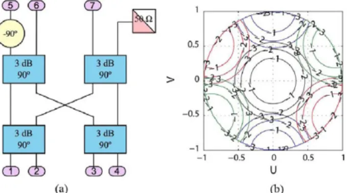
Fig. 3. (a) Scheme of a 4 X 3 modify Butler matrix, (b) GEODA cell array factor when the network is connected. Each color is a different beam.
Fig. 4. 4 x 3 proposed dissipative network.
Showing that total mean network losses are independent of its configuration, being a fourth of the total power. The homo-geneous losses case is obtained when / = 1/2, in which each beam has 1.25 dB losses.
The steering direction of the three orthogonal beams with the desired 6Q elevation angle depends on signal factors, (a, b), and on the distance between elements of the array, (d), as
sin(0o)
\/37rd cos
/ a2 + b2- l \
V 2ab J (18)
Several dissipative networks for triangular arrays have been studied. It is important to bear in mind the fact that the appear-ance of intrinsic side lobes and diffraction must be considered and avoided, as shown in [9], where the truncated Butler net-work for three radiating elements shown in Fig. 3(a) was ana-lyzed, presenting two main lobes when it was applied to a tri-angular cell array. Fig. 3(b) depicts expected array factor if the network is applied to GEODA subarray cell.
To obtain the proper signal network distribution that gener-ates the desired beams, the scattering matrix of the proposed network, (19), must be matched to the desired scattering matrix pattern previously analyzed, (7). After comparison, scattering parameters of the network under study are giving by
(mod [ST])2
c 4 - 3 c
c
4 — 3c c c
c c c
c c 4 — 3c c4 — 3c c c
(20)
arg[ST] = •K 2
T
0 0
T
it
2
7T
2 7T
—7T
— 7 T
2
— 7 T
2
T 3TT
2
T T
—7T
, T = tan" 1
/-27I^\
(21)
The behavior of the network is governed by the value of the central coupler c, as shown in (20) and (21). Relations between network components obtained after study are
cos(a) = \/l — c with sin(a)
03
±Vc
•4>A +
o
(22)
(23)
The sign in sin(a) = ± \ / c determines the desired elevation steering direction ±0o of the three orthogonal beams. In the above analysis, sin(cí) = +y/c has been considered. A com-plementary beam-former network could be obtained by using in the study sin(a) — —\[c, as shown in Section V. Moreover, note that </>3 and (f>4 are fixed phase shifters not related to the de-sired steering direction 6Q of the three orthogonal beams but to the relative phases between array ports needed to generate the different desired beams.
The relation between the desired steering direction angle 9Q and the phase shift between elements ¡3 was given by (5). The steering direction of orthogonal beams as well as losses associ-ated with each beam depend on the coupler c as
sin(0o) = tan
jga
- 1 0 1 o g ( l - - )
-lOlog(ijc).
(24)
(25)
(26)
- 1 0 - 2 0 - 3 0 - 4 0 - 5 0 -60 -70 -80
7: c = 0.0;u = 0.0°
/ ;c = 0.1:8 = 18.4°
•/•!•——•¿c-=02;Á-2BB'>
I | :C = 0.3;a = 33.2'
-<^P
| | \
« - 0 4 ii - 39 2°
¡0 = 0.5:0 = 45.0°: ^c = 0 8:c> = 63.4° o = 0 6:ri = 50 8° ^^c = 6.9:5 = 71.6° :c = 0.7;cf = 56.8°: :c = i.0:a = 90.0°
— v
L6„
i i i
¡-0.5 0.6 0.7 0.8 0.9 1 1.1 1.2 1.3 1.4 1.5 Array distance d [^.]
Fig. 5. Beam steering directions 80 depending on parameters c, a, and d.
35
30 25 CO
5 20
10
-5 0
0 0.1 0.2 0.3 0.4 0.5 0.6 0.7 0.8 0.9 1
c-Coupler
Fig. 6. 4 x 3 Beam losses. (Blue) Broadside beam. (Red) 90 steering direction.
Fig. 5 shows beam steering directions #o depending on the pa-rameters c, a and d. Both type of losses, LQO and LQO associated
with broadside and tilted beams respectively, are also depicted in Fig. 6.
Fig. 5 presents the beam steering capabilities of the network, showing that for larger arrays the possible coverage area in the system is reduced. For a beam-switching application, the contin-uous coverage of the system field-of-view is a critical design re-quirement, which means that relative amplitudes between every beam compounding the network must be carefully analyzed. The total losses of the system that must be taken into account are: intrinsic losses of the proposed network (Fig. 6) and losses introduced into the tilted beams because of the beam width of the single element composing the antenna array. The important condition in the design is that both losses should be balanced to provide a quasi-homogeneous radiation pattern in the system
[Sj
A=e~J
B=\/l
• A-B
-j(A + B)
a
— C
-j(A + B) -yTc -(A-B) - J V H
- J V 5 ¿ " ^3 (-{A-B))e-rt°
- ^ - ^ (-j(A + B))e-M*
3\Tc -V~c
{-JiA + B^e-i*3
(A - B^-M*
TABLE I
SCATTERING MATRIX AND LOSSES OF THE 4 X 3 NETWORK
Fig. 7. Microstrip dissipative 4 x 3 proposed network.
field-of-view considered. Losses in software/hardware hybrid architectures are compensated by using amplifiers.
Fig. 6 depicts that the intrinsic network losses for the broad-side beam decrease as c increases, showing that for c-coupler smaller than 0.4 the losses forthe broadside beam will be higher than 5 dB. Therefore, it is important to notice that to implement a proposed network with such a small c-coupler might be im-practical since it would be very difficult to balance such a high intrinsic losses of the network.
IV. IMPLEMENTATION OF THE PROPOSED 4 X 3 NETWORK
In this section, a microstrip implementation of the proposed dissipative network is presented. The aim of this section will be to validate that the signal distribution provided by the net-work is as defined by (20) and (21). The generation of three orthogonal beams with a 6Q elevation angle and an additional one in the broadside direction when the designed network is applied to a triangular cell of three radiating elements will be verified as well. For this purpose, the simple practical case in which all hybrid power couplers composing the network are four-port 3-dB quadrature couplers is assumed. This case is ob-tained when main network parameters are
c = 0.5 witha = 45° (27)
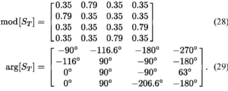
To simplify the implementation and minimize the size of the whole network, commercial four-port 3-dB quadrature hybrid power couplers (Mini Circuits QCN-25) are used. Additional fixed microstrip transmission line lengths will generate required phase shifters. Taking (27) into (20) and (21), the scattering ma-trix associated to this network is
m o d ^ x ] =
arg[53
0.35 0.79 0.35 0.35 - 9 0 ° -116
0° 0°
0.79 0.35 0.35 0.35 0.35 0.35 0.35 0.79
-116.6° 90° 90° 90°
0.351 0.35 0.79 0.35 J
-180° - 9 0 ° - 9 0 ° -206 .6°
-270° -180° 63° -180°
(28)
(29)
To check a correct performance, the network with ideal com-ponents has been simulated by CST Design Studio 2011. Its scattering matrix shows a perfect behavior. Simulated scattering parameters with real measurements of the 4 x 3 dissipative net-work components, fixed phase shifters and QCN —25 90°3 dB
[1 12 13 14
AOl 0.700e'°-91s"
0.327eJ,,M3z" 0.312e-J°'51"
0.312eJ'os3'"
A02 0305e-'OM<-7'
0.312e'0049" 0.327e-J'°969™
0.691e-jo'los''
A03 0.302e-J°412™
0.300eJ'""68" 0.683e-",t17™
0.324eJ'0572"
P
ii8.r±3° 0°±3° ii2.r±2° ii9.r±3°
Losses 32% 70% 33% 32%
60
50
40
S Í J
03
H 20
10
0
""Or*^ Theory
C^^O^ Measurement
/fV V w / \v\if '•• v
Jr '•• //xcL JL
0 3i<L~ * 0 100 200 300
Phi [deg]
Fig. 8. Radiation pattern simulation of the whole system, cell with proposed network, using theoretical (blue) and measured (red) S-parameters.
hybrid couplers, are shown in expressions (30) and (31). These measurements show a good agreement with expectations, with a phase error of ±4° and an amplitude error of ±0.1 dB
mod [Sj
avg[ST] =
0.30 0.72 0.31 0.73 0.32 0.31 0.31 0.32 0.31 0.30 0.31 0.72 -87.0° -114°
-118° 94° - 1 ° 87°
0° 86° 0.301 0.30 0.73
0.3lJ
-182° - 9 0 ° - 9 2 ° -208°
-270° -181° 66° -177°
(30)
(31)
The network has been implemented in a microstrip RO4350B substrate of 0.254 mm thickness as presented in Fig. 7. Fixed phase shifters and four-port 3 — dB 90° hybrid power couplers (QCN-25) have been evaluated independently in order to assure a good performance. The use of commercial chip couplers is helpful when total network dimensions must be minimized. The network presents ±0.3 dB module error and ±5° phase error as summarized in Table I. Signal errors introduced are reason-able, as it is depicted in Fig. 8, where a comparative simulation between radiation patterns of the cell GEODA with theoretical and measured S network parameters shows low beam steering deviations. It is worth noting the use in the simulation of the pre-vious measured radiation pattern of the radiating element com-posing the GEODA cell, which consists of two stacked circular patches with 60° beam width [9]. This beamwidth explains not only the mismatch between factor array and radiation pattern el-evation steering direction OQ, shifting from —41.9° to —23.1°, but also the increase of side lobes shown in following radiation pattern measurements of the GEODA cell with the implemented network.
Fig. 8 shows an almost continuous coverage by using a patch element with a 60° beamwidth.
Fig. 9. Whole system, dissipative 4 x 3 network with GEODA cell array, in the anechoic chamber of the Radiation Group at UPM.
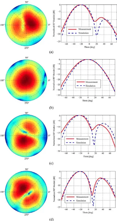
of the Radiation Group at Technical University of Madrid as shown in Fig. 9. Measurements confirm the generation of one beam in the broadside steering direction with an error of ±3° and three orthogonal beams equidistant in azimuth 120° ± 5° with an elevation of—23° ± 2 ° , as expected, depicted in Fig. 10. The radiation patterns associated with the three tilted beams present an increased secondary lobe with a peak of—5 dB with respect to the main beam. Comparisons between measured and simulated radiation patterns associated with each beam have shown a good. Main lobe shapes and steering directions fit prop-erly. The three tilted beams present acceptable smooth varia-tions in amplitude, ± 2 dB, and azimuth, ±7.5°. These devia-tions might be related to a mismatch between the built and the simulated patch array structure.
V. A 7 X 3 B F N BY USING COMPLEMENTARY NETWORKS
To find a beam pattern as homogeneous as possible leads to consider the use of switching beam-formers with higher number of beams. While the number of beams provided by the network is increased, the depointing losses associated with the switching between contiguous beams are reduced. In this section, a new 7 x 3 network is proposed by combining two complementary 4 x 3 networks as described in Fig. 11. The practical imple-mentation is composed of the designed network in the previous section (BFN A) and its complementary network that generates same beams but rotated 180° in azimuth (BFN B).
Design parameters of BFN B are obtained by considering in the analysis the relation (32)
Then
COS(CK) = y/l — c withsin(o!) = —yfc.
c = 0 . 5 witha = - 4 5 °
fc =fa + | = 0°.
(32)
(33)
(34)
Being the expressions governing complementary networks as follow:
0 = ->/§* y sin(0o)
A
sin(0o) =
1 A
V3ñd tan
-2(y/T=c)
H
(35)(36)
/ >
/
/ »i '
^ — ^ — Measurement
mt *m m Simulation
Ns !
V
\\l \ \
U ; i 3i
— i i 1
\
-60 -40 -20 0 20 40 Thcia [dcg]
(a)
i
in
Í
-25
-11)
- M
Á^ \ ^V;
/' \
ft
1
^ " ^ ^ Measurement \ — — — Simulation 1 | ; V
-60 -40 -20 0 20 40 Theta [tlcg]
-10
-20 -25 -10
/ » ^ \
/
^ ^ ^ ^ Measurement
— — — Simulation
' V
> 1 \ \
-60 -40 -20
(c)
/TT\|
/
\
f^%
1
Yp
J^
f ^ ^ ^ ^ Measurement 1 ^ ^ « Simulation
1 *
{
f -20 r _
-60 -40 -20 0 20 40 60 Theta [deg]
Fig. 10. (a), (b), (c), and (d) Measured radiation patterns of the beam forming network and cell subarray GEODA by exciting All, AI2, AI3, and AI4 respec-tively. (Left column) Comparison between measured (red) and simulated (blue) radiation patterns.
Considering the case under study, and taking into account the expressions above, it is shown the desired 180° rotation beams
(3 = 116.6° with BOB = 41.9° = -90A. (37)
Losses associated with the BFN B are the same as in the simple BFN A.
BFNA
^an — 90° 3dB
Patch 03
^Qfi 90°
3dB
Patch 0 2
^«n — 3dB
Patch Q1
E&Q ^an
BFNB
Fig. 11. 7 x 3 BFN Scheme.
Fig. 12. Implementation of the 7 x 3 BFN.
TABLE II
SCATTERING MATRIX AND LOSSES OF THE 7 X 3 NETWORK
1A
2A
3A 4A
IB 2B
3B
4B
Patch 1-02
0AQe}0-70w
0.21e--'0-1911 022eJO-822lc
0.2ieJ'o-34"
0 S 2 É, J 0 . 9 S T I 0 20^)0.85,1
0 24e; o . 8 5 í t 0 2 0 ^ 0 . 3 4 7 1
Patch 2-03
0.21e--f0o5,T 0.22e-i°16n
0.22e>0Sln
0.48e^'023,T 0 2ie; o . 3 3 T i
0.23e''085TI 0 1 9 e; 0 . 8 3 n
QA9ejo.<>(,T,
Patch 3-04
0.20e-J'°-66,t
O^Oe--"11771
0.46e-io-201t 0 2 l eJ 0 . 3 71 l 022eJt)3i1l
0.24ejOS3lt
0.53e--,'°-53,t
0.22ejU28Tt
P
116°±1° 0°±4° 112.1°±1° 113.8°±2° -114.3°±2° 0°±2° -113.5°±2° -116.5°±5°
Losses 68% 86% 69% 68% 64% 85% 63% 67%
lower due to coupler combiner/divider between complemen-tary networks. Table II summarizes measurements of scattering parameters of the whole network, where is shown ±0.3 dB error module and a ±5° error phase. Fig. 13(a) shows the mea-surement of the radiation pattern of the broadside beam, and Fig. 13(b) depicts the measurement of the general radiation pat-tern of a tilted beam. Besides, main plane sections of measured and simulated radiation patterns are also presented, showing similar characteristics as previous network A (Fig. 10). Hence, these measurements show a successful system behavior, pro-viding desired beams.
VI. CONCLUSIONS
BFN for triangular subarrays of three radiating elements has been studied. Intrinsic features of lossless networks limit the
-40 -20 0 20 40 Theta [deg]
Z -25
v ^ v \\
v\
A
il
if
1
I
V I
i
_ _ Measurement Simulationi \
-20 0 20 Theta [deg]
Fig. 13. Measurements of the radiation pattern of the broadside beam (a), and the general radiation pattern of a tilted beam, (b). Measured (red) and simulated (blue) sections of the main plane radiation patterns for broadside (c), and tilted (d) beams.
number of beams generated leading the investigation to dissi-pative network. A novel quasi-orthogonal network providing three orthogonal beams in a desired 9Q elevation angle and an extra broadside one has being proposed. Besides, a 7 x 3 net-work based on two complementary of those novel beam-formers has been described. Practical implementations of both networks have been applied to GEODA triangular subarray cell. Measure-ments ensure a correct behavior of both systems, proving the effectiveness of the proposed innovative BFN design.
REFERENCES
[1] A. Torre, J. Gonzalo, M. Pulido, and R. M. Rodriguez-Osorio, "New generation ground segment architecture for LEO satellites," in Proc.
57th Int. Astronautical Congr., Valencia, Spain, Oct. 2006, pp.
221-226.
[2] C. A. Balanis, Modern Antenna Handbook. New York, NY, USA: Wiley, 2008.
[3] L. C. Godara, Smart Antennas, 1st ed. Boca Raton, FL, USA: CRC. [4] M. A. Salas Natera, A. Garcia Aguilar, J. Mora Cueva, J. M. Fernández, P. Padilla Da La Torre, J. García-Gaseo Trujillo, R. M. Rodriguez-Os-orio, M. Sierra-Peréz, L. De Haro Ariet, and M. S. Castañer, 'New Antenna Array Architectures for Satellite Communications, Advances in Satellite Communications ," in Advances in Satellite
Communica-tions, M. Karimi and Y. Labrador, Eds. Madrid, Spain: Universidad
[8]
[9]
[11]
[5] R. Mailloux, Phased Array Antenna Handbook. Norwood, MA, USA: Artech House.
[6] R. O. Schmidt, "Multiple emitter location and signal parameter esti-mation," in Proc. RADC Spectrum Estimation Workshop, Griffiss Air Force Base, NY, USA, 1979, pp. 243-258.
[7] R. C. Johnson and H. Jasik, Antenna Engineering Handbook. New York, NY, USA: McGraw-Hill, 1984.
J. García-Gaseo Trujillo, M. Salas Natera, I. Montesinos, M. Arias Campo, M. Sierra Pérez, and R. Martinez, "GEODA-GRUA: Adap-tive multibeam conformal antenna for satellites communications," pre-sented at the 30th URSI General Assembly and Sci. Symp. Int. Union of Radio Sci., Istanbul, Turkey, Aug. 2011.
J. García-Gaseo Trujillo, M. Sierra Pérez, A. Novo Garcia, and M. Vera-Isasa, "Multibeam network design and measurement for trian-gular array of three radiating elements," presented at the 5th Eur. Conf. Antennas and Propagation, Rome, Italy, Apr. 2011.
[10] B. Tomasic, J. Turtle, and S. Liu, "A geodesic sphere phased array an-tenna for satellite control and communication," presented at the XXVII General Assembly of the Int. Union of Radio Sci., Maastricht, The Netherlands, Aug. 2002.
S. Liu, B. Tomasic, S. Hwang, and J. Turtle, "The geodesic dome phased array antenna (GDPAA) for satellite operations support," in
Proc. IEEE 18th Int. Conf. Appl. Electromagnetics and Commun.,
Dubrovnik, Croatia, Apr. 2006, p. 1.
[12] I. Montesinos, M. Sierra Pérez, J. L. Fernández, R. Matinez, and J. L. Masa, "GEODA: Adaptive antenna of multiple planar arrays for satel-lite communications," presented at the Eur. Conf. Antenna and Propa-gation, Berlin, Germany, 2009.
[13] A. K. Bhattacharyya, Phased Array Antennas. New York, NY, USA: Wiley.
[14] R. H. Roy and T. Kailath, "Esprit-estimation of signal parameters via rotational invariance techniques," IEEE Trans. Acoust., Speech, Signal
Process., vol. 37, no. 7, pp. 984-995, Jul. 1989.
[15] R. Hansen, Phased Array Antennas. Hoboken, NJ, USA: Wiley, 1998.
[16] J. Butler and R. Lowe, "Beam-forming matrix simplifies design of elec-tronically scanned antennas," Electron. Design, vol. 9, pp. 170-173, Apr. 1961.
[17] J. Blass, "Multidirectional antenna - A new approach to stacked beams," in IRE Int. Convention Record, 1960, pp. 48-50, Part 1. [18] W. Rotman and R. Turner, "Wide-angle microwave lens for line source
applications," IEEE Trans. Antennas Propag., vol. AP-11, no. 6, pp. 623-632, Jun. 1963.
J. H. Kim, K. D. Jang, W. J. Byun, B. S. Kim, K. S. Kim, M. S. Song, and W. S. Park, "Design of a novel switched four beam array antenna for millimeter wave," in Proc. IEEE Antennas and Propagation Soc.
Int. Symp., Jun. 9-15, 2007, pp. 2654-2657.
Javier García-Gaseo Trujillo was born in 1986
in Toledo, Spain. He received the M.Sc. degree in telecommunication engineering from the Technical University of Madrid (UPM), Madrid, Spain, in 2009.
Since then, he is a Ph.D. degree student in the Radiation Group, Signal, Systems and Radio-communications Department, UPM. His main research interest is reconfigurable planar phased array antennas, focusing on multi-beamforming networks and transmission/reception modules for [19]
Alvaro Noval Sánchez de Toca was born in Madrid,
Spain, in 1986. He received the M.Sc. degree in telecommunication engineering from the Technical University of Madrid (UPM), Madrid, Spain, in 2011.
He is currently working toward the Ph.D. degree in the Radiation Group, UPM, as a recipient of a Spanish Ministry of Science and Innovation Schol-arship (2011-2015). His research interests include active array antenna design with electronic steering for satellite communications. He is participating in national and international investigation.
Ignacio Montesinos-Ortego was born in León,
Spain, on April 19, 1984. He received the B.S., M.S., and Ph.D. degrees in electrical engineering from Technical University of Madrid (UPM), Madrid, Spain, in 2007, 2009, and 2012, respectively.
From 2007 to 2009, was a Research Associate in the Radiation Group of UPM. From 2009 to 2011, he became a Research Associate at Ando & Hirokawa Laboratory at Tokyo Institute of Tech-nology, Tokyo, Japan. His researching interests are planar waveguide arrays, smart antenna arrays and
h
* T É
beam-forming networks.
material structures with
José-Manuel Fernández was born in Lausanne,
Switzerland, in 1977. He received the Diplome d'Ingénieur en Electricité from the Ecole Polytech-nique Fedérale de Lausanne (EPFL), Lausanne, Switzerland, in 2003. He received the M.S. and Ph.D. degrees in electrical engineering from Tech-nical University of Madrid (UPM), Madrid, Spain, in 2003 and 2009, respectively.
Since 2009, he is a Postdoctoral Researcher in the Radiation Group at Technical University of Madrid. His current research interest is in the field of meta-emphasis on planar antenna applications.
L and S bands.
Manuel Sierra-Peréz was born in Zaragoza, Spain,
in 1952. He received the Master degree (Telecommu-nication Engineer) from the Technical University of Madrid (UPM), Madrid, Spain, in 1975 and the Ph.D. degree in 1980.