Evaluación – Prueba de habilidades prácticas CCNP
Johnathan Castelblanco Chavez Código: 1012.353.130
TRABAJO DE PRUEBA DE HABILIDADES PRACTICAS
Diplomado de Profundización CCNP
Director de Curso:
Ing. Juan Carlos Vesga
Tutor de Curso:
Ing. Gerardo Granados Acuña
Línea de Profundización:
Redes de Telecomunicaciones
Universidad Nacional Abierta y a Distancia UNAD
Escuela de Ciencias Básicas, Tecnología e Ingeniería - ECBTI
Ingeniería de Telecomunicaciones
Contenido
Introducción ...3
1.1 Prueba de habilidades ... 4
1.1.1 Escenario 1 ... 4
1.1.2 Escenario 2 ... 13
1.1.3 Escenario 3 ... 21
Conclusiones ... 32
Introducción
El presente documento muestra el desarrollo de tres escenarios prácticos de redes
de Routeres y Switches; para dar solución a cada escenario se requirió de la
aplicación de las diferentes habilidades en configuración de protocolos como OSPF,
EIGRP, BGP, VTP y DTP en equipos activos Cisco, dichas habilidades fueron
adquiridas en el curso del diplomado de profundización Cisco CCNP, opción de
grado del programa de Ingeniería de telecomunicaciones de la UNAD.
El desarrollo de escenarios prácticos permite contextualizar situaciones reales de
redes interconectas, de manera que el estudiante plante soluciones desde
1.1 Prueba de habilidades
1.1.1 Escenario 1
Figura 1. Topología Escenario 1
1. Aplique las configuraciones iniciales y los protocolos de enrutamiento para los routers R1, R2, R3, R4 y R5 según el diagrama. No asigne passwords en los routers. Configurar las interfaces con las direcciones que se muestran en la topología de red.
Desarrollo:
R1: Se aplica las configuraciones iniciales activando las interfaces seriales con su correspondiente dirección IP, se activa el protocolo OSPF en el área correspondiente.
R1#enable
R1#configure terminal
Enter configuration commands, one per line. End with CNTL/Z. R1(config)#!
R1(config)#hostname R1
R1(config)#no ip domain-lookup R1(config)#!
R1(config)#interface Serial1/0
R1(config-if)# description ### PHYSICAL FRAME RELAY INTERFACE ### R1(config-if)# no ip address
R1(config-if)# encapsulation frame-relay R1(config-if)# serial restart-delay 0 R1(config-if)# no frame-relay inverse-arp R1(config-if)# no shut
R1(config-if)# exit R1(config)#!
R1(config)#interface Serial1/0.122 point-to-point
R1(config-subif)# description ### FRAME RELAY LINK TO R2 ### R1(config-subif)# ip address 10.103.12.1 255.255.255.0
R1(config-subif)# ip ospf 1 area 0
R1(config-subif)# frame-relay interface-dlci 122 R1(config-fr-dlci)# exit
R1(config-subif)#!
R1(config-subif)#router ospf 1 R1(config-router)# exit
R1(config)#!
R1(config)#line con 0
R1(config-line)# logging sync R1(config-line)# no exec-timeout R1(config-line)#!
R2: Se aplica las configuraciones iniciales activando las interfaces seriales con su correspondiente dirección IP, se activa el protocolo OSPF en el área correspondiente.
R2#enable
R2#configure terminal
Enter configuration commands, one per line. End with CNTL/Z. R2(config)#!
R2(config)#hostname R2
R2(config)#no ip domain-lookup R2(config)#!
R2(config)#interface Serial1/0
R2(config-if)# description ### PHYSICAL FRAME RELAY INTERFACE ### R2(config-if)# encapsulation frame-relay
R2(config-if)# no frame-relay inverse-arp R2(config-if)# no shut
R2(config-if)#!
R2(config-if)#interface Serial1/0.221 point-to-point
R2(config-subif)# description ### FRAME RELAY LINK TO R1 ### R2(config-subif)# ip address 10.103.12.2 255.255.255.0
R2(config-subif)# ip ospf 1 area 0
R2(config-subif)# frame-relay interface-dlci 221 R2(config-fr-dlci)# exit
R2(config-subif)#!
R2(config-subif)#interface Serial1/0.223 point-to-point
R2(config-subif)# description ### FRAME RELAY LINK TO R3 ### R2(config-subif)# ip address 10.103.23.2 255.255.255.0
R2(config-subif)# ip ospf 1 area 0
R2(config-subif)# frame-relay interface-dlci 223 R2(config-fr-dlci)# exit
R2(config-subif)#!
R2(config-subif)#router ospf 1 R2(config-router)# exit
R2(config)#!
R2(config)#line con 0
R2(config-line)# logging sync R2(config-line)# no exec-timeout R2(config-line)#!
R3: Se aplica las configuraciones iniciales activando las interfaces seriales con su correspondiente dirección IP, se activa el protocolo OSPF en el área correspondiente.
R3#enable
R3#configure terminal
Enter configuration commands, one per line. End with CNTL/Z. R3(config)#!
R3(config)#hostname R3
R3(config)#no ip domain-lookup R3(config)#!
R3(config)#interface Serial1/0
R3(config-if)# description ### PHYSICAL FRAME RELAY INTERFACE ### R3(config-if)# encapsulation frame-relay
R3(config-if)# no frame-relay inverse-arp R3(config-if)# no shut
R3(config-if)# exit R3(config)#!
R3(config)#interface Serial1/0.322 point-to-point
R3(config-subif)# description ### FRAME RELAY LINK TO R2 ### R3(config-subif)# ip address 10.103.23.3 255.255.255.0
R3(config-subif)# ip ospf 1 area 0
R3(config-subif)# frame-relay interface-dlci 322 R3(config-fr-dlci)# exit
R3(config-subif)#!
R3(config-subif)#interface Serial1/0.324 point-to-point
R3(config-subif)# description ### PHYSICAL FRAME RELAY INTERFACE ### R3(config-subif)# ip address 172.29.34.3 255.255.255.0
R3(config-subif)# frame-relay interface-dlci 324 R3(config-fr-dlci)# no shut
R3(config-subif)#!
R3(config-subif)#router ospf 1 R3(config-router)# exit
R3(config)#!
R3(config)#router eigrp 10 R3(config-router)# no auto
R3(config-router)# network 172.29.0.0 0.0.255.255 R3(config-router)# exit
R3(config)#line con 0
R3(config-line)# logging sync R3(config-line)# no exec-timeout R3(config-line)#!
R3(config-line)#end
R4:Se aplica las configuraciones iniciales activando las interfaces seriales con su correspondiente dirección IP, se activa el protocolo OSPF en el área
correspondiente.
R4#enable
R4#configure terminal
Enter configuration commands, one per line. End with CNTL/Z. R4(config)#!
R4(config)#hostname R4
R4(config)#no ip domain-lookup R4(config)#!
R4(config)#interface Serial1/0
R4(config-if)# description ### PHYSICAL FRAME RELAY INTERFACE ### R4(config-if)# encapsulation frame-relay
R4(config-if)# no frame-relay inverse-arp R4(config-if)# no shut
R4(config-if)#!
R4(config-if)#interface Serial1/0.423 point-to-point
R4(config-subif)# description ### FRAME RELAY LINK TO R3 ### R4(config-subif)# ip address 172.29.34.4 255.255.255.0
R4(config-subif)# frame-relay interface-dlci 423 R4(config-fr-dlci)# exit
R4(config-subif)#!
R4(config-subif)#interface Serial1/0.425 point-to-point
R4(config-subif)# description ### FRAME RELAY LINK TO R5 ### R4(config-subif)# ip address 172.29.45.4 255.255.255.0
R4(config-subif)# frame-relay interface-dlci 425 R4(config-fr-dlci)# exit
R4(config-subif)#!
R4(config-subif)#router eigrp 10 R4(config-router)# no auto
R4(config)#!
R4(config)#line con 0
R4(config-line)# logging sync R4(config-line)# no exec-timeout R4(config-line)#!
R4(config-line)#end
R5: Se aplica las configuraciones iniciales activando las interfaces seriales con su correspondiente dirección IP, se activa el protocolo OSPF en el área correspondiente.
R5#enable
R5#configure terminal
Enter configuration commands, one per line. End with CNTL/Z. R5(config)#!
R5(config)#hostname R5
R5(config)#no ip domain-lookup R5(config)#!
R5(config)#interface Serial1/0
R5(config-if)# description ### PHYSICAL FRAME RELAY INTERFACE ### R5(config-if)# encapsulation frame-relay
R5(config-if)# no frame-relay inverse-arp R5(config-if)# no shut
R5(config-if)#!
R5(config-if)#interface Serial1/0.524 point-to-point
R5(config-subif)# description ### FRAME RELAY LINK TO R5 ### R5(config-subif)# ip address 172.29.45.5 255.255.255.0
R5(config-subif)# frame-relay interface-dlci 524 R5(config-fr-dlci)# exit
R5(config-subif)# exit R5(config)#!
R5(config)#router eigrp 10 R5(config-router)#no auto
R5(config-router)#network 172.29.0.0 0.0.255.255 R5(config-router)#!
2. Cree cuatro nuevas interfaces de Loopback en R1 utilizando la asignación de direcciones 10.1.0.0/22 y configure esas interfaces para participar en el área 0 de OSPF.
R1#configure terminal
Enter configuration commands, one per line. End with CNTL/Z. R1(config)#interface loopback0
R1(config-if)#ip address 10.1.0.1 255.255.255.0 R1(config-if)#ip ospf 1 area 0
R1(config-if)#ip ospf network point-to-point R1(config-if)#!
R1(config-if)#interface loopback1
R1(config-if)#ip address 10.1.1.1 255.255.255.0 R1(config-if)#ip ospf 1 area 0
R1(config-if)#ip ospf network point-to-point R1(config-if)#!
R1(config-if)#interface loopback2
R1(config-if)#ip address 10.1.2.1 255.255.255.0 R1(config-if)#ip ospf 1 area 0
R1(config-if)#ip ospf network point-to-point R1(config-if)#!
R1(config-if)#interface loopback3
R1(config-if)#ip address 10.1.3.1 255.255.255.0 R1(config-if)#ip ospf 1 area 0
R1(config-if)#ip ospf network point-to-point R1(config-if)#end
3. Cree cuatro nuevas interfaces de Loopback en R5 utilizando la asignación de direcciones 172.5.0.0/22 y configure esas interfaces para participar en el Sistema Autónomo EIGRP 10.
R5#configure terminal
Enter configuration commands, one per line. End with CNTL/Z. R5(config)#interface loopback0
R5(config-if)#ip address 172.5.0.1 255.255.255.0 R5(config-if)#!
R5(config-if)#interface loopback1
R5(config-if)#ip address 172.5.1.1 255.255.255.0 R5(config-if)#!
R5(config-if)#interface loopback2
R5(config-if)#!
R5(config-if)#interface loopback3
R5(config-if)#ip address 172.5.3.1 255.255.255.0 R5(config-if)#exit
R5(config)#router eigrp 10
R5(config-router)#network 172.5.0.0 0.0.255.255 R5(config-router)#end
4. Analice la tabla de enrutamiento de R3 y verifique que R3 está aprendiendo
las nuevas interfaces de Loopback mediante el comando show ip route.
172.5.0.0/24 is subnetted, 4 subnets
D 172.5.1.0 [90/2809856] via 172.29.34.4, 00:00:41, Serial0/0.324 D 172.5.0.0 [90/2809856] via 172.29.34.4, 00:00:41, Serial0/0.324 D 172.5.3.0 [90/2809856] via 172.29.34.4, 00:00:41, Serial0/0.324 D 172.5.2.0 [90/2809856] via 172.29.34.4, 00:00:41, Serial0/0.324 172.29.0.0/24 is subnetted, 2 subnets
C 172.29.34.0 is directly connected, Serial0/0.324
D 172.29.45.0 [90/2681856] via 172.29.34.4, 00:03:39, Serial0/0.324 10.0.0.0/24 is subnetted, 6 subnets
O 10.1.3.0 [110/129] via 10.103.23.2, 00:08:45, Serial0/0.322 O 10.1.2.0 [110/129] via 10.103.23.2, 00:08:45, Serial0/0.322 O 10.1.1.0 [110/129] via 10.103.23.2, 00:08:45, Serial0/0.322 O 10.1.0.0 [110/129] via 10.103.23.2, 00:08:45, Serial0/0.322 O 10.103.12.0 [110/128] via 10.103.23.2, 00:08:46, Serial0/0.322 C 10.103.23.0 is directly connected, Serial0/0.322
5. Configure R3 para redistribuir las rutas EIGRP en OSPF usando el costo de 50000 y luego redistribuya las rutas OSPF en EIGRP usando un ancho de banda T1 y 20,000 microsegundos de retardo.
Enter configuration commands, one per line. End with CNTL/Z. R3(config)#router ospf 1
R3(config-router)#redistribute eigrp 10 metric 50000 subnets R3(config-router)#exit
R3(config)#router eigrp 10
R3(config-router)#redistribute ospf 1 metric ?
<1-4294967295> Bandwidth metric in Kbits per second
R3(config-router)#redistribute ospf 1 metric ?
<1-4294967295> Bandwidth metric in Kbits per second
R3(config-router)#redistribute ospf 1 metric ?
<1-4294967295> Bandwidth metric in Kbits per second
R3(config-router)#redistribute ospf 1 metric ?
<1-4294967295> Bandwidth metric in Kbits per second
R3(config-router)#redistribute ospf 1 metric ?
<1-4294967295> Bandwidth metric in Kbits per second
R3(config-router)#redistribute ospf 1 metric 1544 ?
<0-4294967295> EIGRP delay metric, in 10 microsecond units
R3(config-router)#redistribute ospf 1 metric 1544 2000 ? <0-255> EIGRP reliability metric where 255 is 100% reliable
R3(config-router)#redistribute ospf 1 metric 1544 2000 255 ?
<1-255> EIGRP Effective bandwidth metric (Loading) where 255 is 100% loaded
R3(config-router)#redistribute ospf 1 metric 1544 2000 255 1 ? <1-65535> EIGRP MTU of the path
R3(config-router)#redistribute ospf 1 metric 1544 2000 255 1 1500 R3(config-router)#end
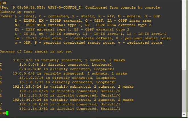
6. Verifique en R1 y R5 que las rutas del sistema autónomo opuesto existen en
Figura 3. Topología Escenario 2
Información para configuración de los Routers
R1 Interfaz Dirección IP Máscara
Loopback 0 1.1.1.1 255.0.0.0
Loopback 1 11.1.0.1 255.255.0.0 S 0/0 192.1.12.1 255.255.255.0 sR2 Interfaz Dirección IP Máscara
Loopback 0 2.2.2.2 255.0.0.0
Loopback 1 12.1.0.1 255.255.0.0 S 0/0 192.1.12.2 255.255.255.0 E 0/0 192.1.23.2 255.255.255.0 R3 Interfaz Dirección IP Máscara
Loopback 0 3.3.3.3 255.0.0.0
Loopback 1 13.1.0.1 255.255.0.0 E 0/0 192.1.23.3 255.255.255.0
S 0/0 192.1.34.3 255.255.255.0
R4 Interfaz Dirección IP Máscara
Loopback 0 4.4.4.4 255.0.0.0
Loopback 1 14.1.0.1 255.255.0.0 S 0/0 192.1.34.4 255.255.255.0
Figura 4. Topología Implementada en GNS3 Escenario 2
Desarrollo:
Se configuran las diferentes interfaces loopback e interfaces seriales con las direcciones IP indicadas en los diferentes routers.
R1(config)#interface lo0
R1(config-if)#ip address 1.1.1.1 255.0.0.0 R1(config-if)#description Loopback 0 R1(config-if)#exit
R1(config)#interface lo1
R1(config-if)#description Loopback 1
R1(config-if)#ip address 11.1.0.1 255.255.0.0 R1(config-if)#exit
R1(config)#interface s1/0 R1(config-if)#description s1/0
R1(config-if)#ip address 192.1.12.1 255.255.255.0 R1(config-if)#exit
R1#conf t
Enter configuration commands, one per line. End with CNTL/Z. R1(config)#interface s1/0
R1(config-if)#clock rate 128000 R1(config-if)#no sh
R1(config-if)#end
R2#conf t
Enter configuration commands, one per line. End with CNTL/Z. R2(config)#interface lo0
R2(config-if)#ip address 2.2.2.2 255.0.0.0 R2(config-if)#exit
R2(config)#interface lo1
R2(config-if)#description Loopback 1
R2(config-if)#ip address 12.1.0.1 255.255.255.0 R2(config-if)#no sh
R2(config-if)#exit
R2(config)#interface s1/0 R2(config-if)#description s1/0
R2(config-if)#ip address 192.1.12.2 255.255.255.0 R2(config-if)#no sh
R2(config-if)#exit
R2(config)#interface s1/1 R2(config-if)#description s1/1
R2(config-if)#ip address 192.1.23.2 255.255.255.0 R2(config-if)#clock rate 128000
R2(config-if)#no sh R2(config-if)#end
R3#conf t
Enter configuration commands, one per line. End with CNTL/Z. R3(config)#interface lo0
R3(config-if)#description Loopback 0 R3(config-if)#ip address 3.3.3.3 255.0.0.0 R3(config-if)#exit
R3(config)#interface lo1
R3(config-if)#description Loopback 1
R3(config-if)#ip address 13.1.0.1 255.255.0.0 R3(config-if)#exit
R3(config)#interface s1/1 R3(config-if)#description s1/1
R3(config-if)#ip address 192.1.34.3 255.255.255.0 R3(config-if)#clock rate 128000
R3(config-if)#no sh
R4#conf t
R4(config-if)#description Loopback 0 R4(config-if)#ip address 4.4.4.4 255.0.0.0 R4(config-if)#exit
R4(config)#Interface s1/0 R4(config-if)#description s1/0
R4(config-if)#ip address 192.1.34.4 255.255.255.0 R4(config-if)#no sh
R4(config-if)#exit
R4(config)#interface lo1
R4(config-if)#description Loopback 1
R4(config-if)#ip address 14.1.0.1 255.255.0.0 R4(config-if)#exit
R4(config)#end
1. Configure una relación de vecino BGP entre R1 y R2. R1 debe estar en AS1 y R2 debe estar en AS2. Anuncie las direcciones de Loopback en BGP. Codifique los ID para los routers BGP como 11.11.11.11 para R1 y como 22.22.22.22 para R2. Presente el paso a con los comandos utilizados y la salida del comando show ip route.
R1#conf t
Enter configuration commands, one per line. End with CNTL/Z. R1(config)#router bgp 100
R1(config-router)#neighbor 192.1.12.3 remote-as 200 R1(config-router)#network 1.1.1.0 mask 255.0.0.0 % BGP: Incorrect network or mask configured
R1(config-router)#network 1.1.1.0 mask 255.255.255.0
R2#conf t
Enter configuration commands, one per line. End with CNTL/Z. R2(config)#router bgp 200
R2(config-router)#neighbor 192.1.12.1 remote-as 100 R2(config-router)#network 2.2.2.0
2. Configure una relación de vecino BGP entre R2 y R3. R2 ya debería estar configurado en AS2 y R3 debería estar en AS3. Anuncie las direcciones de Loopback de R3 en BGP. Codifique el ID del router R3 como 33.33.33.33. Presente el paso a con los comandos utilizados y la salida del comando show ip route.
R3#conf t
Enter configuration commands, one per line. End with CNTL/Z. R3(config)#router bgp 300
R3(config-router)#neighbor 192.1.23.0 remote-as 200 R3(config-router)#network 2.2.2.0 mask 255.255.255.0 R3(config-router)#network 12.1.0.0 mask 255.255.255.0
R3#conf t
Enter configuration commands, one per line. End with CNTL/Z. R3(config)#router bgp 300
3. Configure una relación de vecino BGP entre R3 y R4. R3 ya debería estar configurado en AS3 y R4 debería estar en AS4. Anuncie las direcciones de Loopback de R4 en BGP. Codifique el ID del router R4 como 44.44.44.44. Establezca las relaciones de vecino con base en las direcciones de Loopback 0. Cree rutas estáticas para alcanzar la Loopback 0 del otro router. No anuncie la Loopback 0 en BGP. Anuncie la red Loopback de R4 en BGP. Presente el paso a con los comandos utilizados y la salida del comando show ip route.
R3#conf t
Enter configuration commands, one per line. End with CNTL/Z. R3(config)#router bgp 300
R4#conf t
Enter configuration commands, one per line. End with CNTL/Z. R4(config)#router bgp 400
R4(config-router)#neighbor 192.1.12.0 remote-as 100 R4(config-router)#network 1.1.1.0 mask 255.255.255.0 R4(config-router)#network 11.1.0.0 mask 255.255.255.0 R4(config-router)#exit
R4(config)#router bgp 400
R4(config-router)#neighbor 192.1.23.0 remote-as 100 R4(config-router)#neighbor 192.1.12.0 remote-as 200 R4(config-router)#neighbor 192.1.12.0 remote-as 100 R4(config-router)#neighbor 192.1.23.0 remote-as 200 R4(config-router)#network 2.2.2.0 mask 255.255.255.0 R4(config-router)#network 12.1.0.0 mask 255.255.255.0 R4(config-router)#exit
R4(config)#router bgp 400
1.1.3 Escenario 3
Figura 6. Topología Implementada en Packet Tracer
A. Configurar VTP
1.Todos los switches se configurarán para usar VTP para las actualizaciones de VLAN. El switch SWT2 se configurará como el servidor. Los switches SWT1 y SWT3 se configurarán como clientes. Los switches estarán en el dominio VPT llamado CCNP y usando la contraseña cisco.
SWT2(config)#conf t
SWT2(config)#vtp domain CCNP
Changing VTP domain name from NULL to CCNP SWT2(config)#vtp mode server
Device mode already VTP SERVER. SWT2(config)#vtp password cisco
SWT1(config)#conf t
SWT1(config)#vtp domain CCNP
Changing VTP domain name from NULL to CCNP SWT1(config)#vtp mode client
Setting device to VTP CLIENT mode. SWT1(config)#vtp password cisco
Setting device VLAN database password to cisco
2. Verifique las configuraciones mediante el comando show vtp status.
• Al observar el resultado se puede verificar que SWT1 y SWT3 operan modo
VTP Client.
B. Configurar DTP (Dynamic Trunking Protocol)
1. Configure un enlace troncal ("trunk") dinámico entre SWT1 y SWT2. Debido a
que el modo por defecto es dynamic auto, solo un lado del enlace debe
configurarse como dynamic desirable.
SWT1(config)#conf t SWT1(config)#interface f0/1
SWT1(config)#switchport mode dynamic desirable
3. Entre SWT1 y SWT3 configure un enlace "trunk" estático utilizando el comando switchport mode trunk en la interfaz F0/3 de SWT1
SWT1(config)#conf t SWT1(config)#interface f0/3
SWT1(config)#switchport mode trunk
4. Configure un enlace "trunk" permanente entre SWT2 y SWT3.
SWT3(config)#conf t SWT3(config)#interface f0/1
SWT3(config)#switchport mode trunk
SWT2(config)#conf t SWT2(config)#interface f0/2
SWT2(config)#switchport mode trunk
C. Agregar VLANs y asignar puertos.
1. En STW1 agregue la VLAN 10. En STW2 agregue las VLANS Compras (10), Mercadeo (20), Planta (30) y Admon (99)
SWT1(config)#conf t SWT1(config)#vlan 10 SWT1(config)#
SWT2(config)#conf t SWT2(config)#vlan 10
SWT2(config)#name COMPRAS SWT2(config)#vlan 20
SWT2(config)#name MERCADEO SWT2(config)#vlan 30
SWT2(config)#name PLANTA SWT2(config)#vlan 99
SWT2(config)#name ADMON SWT2(config)#end
2. Asocie los puertos a las VLAN y configure las direcciones IP de acuerdo con la siguiente tabla.
Interfaz VLAN Direcciones IP de los PCs
F0/10 VLAN 10 190.108.10.X / 24
F0/15 VLAN 20 190.108.20.X /24
F0/20 VLAN 30 190.108.30.X /24
X = número de cada PC particular
Interfaz VLAN Direcciones IP de los PCs
SWT1 F0/10 VLAN 10 190.108.10.1 / 24
SWT1 F0/15 VLAN 20 190.108.20.1 / 24
SWT1 F0/20 VLAN 30 190.108.30.1 / 24
SWT2 F0/10 VLAN 10 190.108.10.2 / 24
SWT2 F0/15 VLAN 20 190.108.20.2 / 24
SWT2 F0/20 VLAN 30 190.108.30.2 / 24
SWT2 F0/10 VLAN 10 190.108.10.3 / 24
SWT2 F0/15 VLAN 20 190.108.20.3 / 24
Configure el puerto F0/10 en modo de acceso para SWT1, SWT2 y SWT3 y asígnelo a la VLAN 10.
SWT1(config)#conf t SWT1(config)#int f0/1
SWT1(config-if)#switchport mode access SWT1(config-if)#switchport access vlan 10
SWT2(config)#conf t SWT2(config)#int f0/1
SWT2(config-if)#switchport mode access SWT2(config-if)#switchport access vlan 10
SWT3(config)#conf t SWT3(config)#int f0/10
SWT3(config-if)#switchport mode access SWT3(config-if)#switchport access vlan 10
Repita el procedimiento para los puertos F0/15 y F0/20 en SWT1, SWT2 y SWT3. Asigne las VLANs y las direcciones IP de los PCs de acuerdo con la tabla de arriba.
SWT1(config)#conf t SWT1(config)#int f0/15
SWT1(config-if)#switchport mode access SWT1(config-if)#switchport access vlan 20 SWT1(config)#conf t
SWT1(config)#int f0/20
SWT1(config-if)#switchport mode access SWT1(config-if)#switchport access vlan 30
SWT2(config)#conf t SWT2(config)#int f0/15
SWT2(config-if)#switchport mode access SWT2(config-if)#switchport access vlan 20 SWT2(config)#conf t
SWT2(config)#int f0/20
SWT3(config)#conf t SWT3(config)#int f0/15
SWT3(config-if)#switchport mode access SWT3(config-if)#switchport access vlan 20 SWT3(config)#conf t
SWT3(config)#int f0/20
SWT3(config-if)#switchport mode access SWT3(config-if)#switchport access vlan 30
D. Configurar las direcciones IP en los Switches.
1. En cada uno de los Switches asigne una dirección IP al SVI (Switch Virtual Interface) para VLAN 99 de acuerdo con la siguiente tabla de direccionamiento y active la interfaz.
Equipo Interfaz Dirección IP Máscara
SWT1 VLAN 99 190.108.99.1 255.255.255.0
SWT2 VLAN 99 190.108.99.2 255.255.255.0
SWT3 VLAN 99 190.108.99.3 255.255.255.0
SWT1(config)#int vlan 99
SWT1(config-if)#ip address 190.108.99.1 255.255.255.0 SWT1(config-if)#no sh
SWT2(config)#int vlan 99
SWT2(config-if)#ip address 190.108.99.2 255.255.255.0 SWT2(config-if)#no sh
SWT3(config)#int vlan 99
SWT3(config-if)#ip address 190.108.99.3 255.255.255.0 SWT3(config-if)#no sh
E. Verificar la conectividad Extremo a Extremo
• PC compras en SWT1: Ping a Pc Compras en SWT2 y SWT3 exitoso
• PC Planta en SWT1: Ping a Pc Planta en SWT2 y SWT3 exitoso
• Al intentar realizar ping entre un pc de un departamento diferente (Ejemplo entre un pc del área mercado y otro del área planta) no se completa el ping puesto que cada departamento está en una VLAN diferente, incluso cuando están conectados al mismo Switch.
• Al realizar el ping entre los diferentes Switch se tiene obtiene respuesta, lo que confirma que hay una adecuada negociación.
3. Ejecute un Ping desde cada Switch a cada PC. Explique por qué el ping tuvo o no tuvo éxito.
• El ping no se completa puesto que los PCs no están dentro de la misma
Conclusiones
• Cuando se configura el protocolo BGP se puede automatizar una red de varios routers para que intercambien información de rutero entre cada router, en ese proceso de intercambian las tablas de ruteo y se envían actualizaciones, por lo general el protocolo BGP se emplea en Gateways.
• El protocolo VTP permite optimizar la gestión de un dominio de VLANs de manera global sin necesidad de realizar administración en cada equipo switch de la red, ese caso puede operar como servidor o cliente.
• El protocolo EIGRP es una alternativa que mantiene información en dos tablas, una la tabla de vecinos, donde se registran las direcciones IP de los routers adyacentes; la segunda tabla es la de topología donde se guardan las rutas aprendidas de los routers adyacentes.
Referencias Bibliográficas
• Teare, D., Vachon B., Graziani, R. (2015). CISCO Press (Ed). Path Control Implementation. Implementing Cisco IP Routing (ROUTE) Foundation
Learning Guide CCNP ROUTE 300-101. Recuperado de
https://1drv.ms/b/s!AmIJYei-NT1IlnMfy2rhPZHwEoWx
• Froom, R., Frahim, E. (2015). CISCO Press (Ed). Spanning Tree Implementation. Implementing Cisco IP Switched Networks (SWITCH) Foundation Learning Guide CCNP SWITCH 300-115. Recuperado de https://1drv.ms/b/s!AmIJYei-NT1IlnWR0hoMxgBNv1CJ
• room, R., Frahim, E. (2015). CISCO Press (Ed). Fundamentals Review. Implementing Cisco IP Switched Networks (SWITCH) Foundation Learning
Guide CCNP SWITCH 300-115. Recuperado de
https://1drv.ms/b/s!AmIJYei-NT1IlnWR0hoMxgBNv1C
• UNAD (2015). Switch CISCO Security Management [OVA]. Recuperado de https://1drv.ms/u/s!AmIJYei-NT1IlyVeVJCCezJ2QE5c
• Odom, W. (2013). CISCO Press (Ed). CCNA ICND2 Official Exam
Certification Guide. Recuperado de