J.G.M. Van Mier, G. Ruiz, C. Andrade, R.C. Yu and X.X. Zhang (Eds)
FINITE ELEMENT SIMULATION OF SANDWICH PANELS OF
PLASTERBOARD AND ROCK WOOL UNDER MIXED MODE FRACTURE
J.A. ALONSO*, E. REYES† AND J.C. GÁLVEZ†
*Universidad Politécnica de Madrid (UPM) E.U. Arquitectura Técnica.
Avenida Juan de Herrera 6, 28040 Madrid, Spain
e-mail: [email protected] - Web page: http://www.upm.es
†
Universidad Politécnica de Madrid (UPM) ETS de Ingenieros de Caminos, Canales y Puertos Calle Profesor Aranguren s/n, 28004 Madrid, Spain
e-mail: [email protected]; [email protected] - Web page: http://www.upm.es
Key words: Cohesive fracture, sandwich panel, mixed-mode fracture, size-effect
Abstract: This paper presents the results of research on mixed mode fracture of sandwich panels of plasterboard and rock wool. The experimental data of the performed tests are supplied. The specimens were made from commercial panels. Asymmetrical three-point bending tests were performed on notched specimens. Three sizes of geometrically similar specimens were tested for studying the size effect. The paper also includes the numerical simulation of the experimental results by using an embedded cohesive crack model. The involved parameters for modelling are previously measured by standardised tests.
1 INTRODUCTION
The fracture research of sandwich panels of plasterboard and rock wool has been focused on the out-of-plane bending failure. Nevertheless, the use of such as material for internal vertical divisions in building has substantially grown due to the velocity and ease of mounting. In some cases this composite material performs a good solution for noise insulation requirements in building, as it is contemplated by the Spanish Technical Code for Building [1-3].
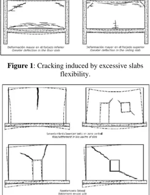
Figures 1 and 2 show a sketch of the typical failure mechanisms of the vertical partitions in a building due to excessive deflections and differential settlements. Both are mixed mode fracture problems of in-plane bending with a composite cohesive material. There is not
enough experimental data to perform a fracture analysis of the problems with such material.
This paper supplies experimental data of mixed mode fracture, with in-plane bending failure, of sandwich panels of plasterboard and rock wool with the specimens being performed with commercial the corresponding sandwich panels. Three similar specimen sizes were also tested for studying the size effect. The load-displacement and load- crack mouth opening displacement (CMOD) curves are presented.
Figure 1: Cracking induced by excessive slabs
flexibility.
Figure 2: Cracking induced by differential settling.
2 EXPERIMENTAL PROGRAMME
The aim of the experimental programme was to study the mixed mode fracture of the sandwich panels of plasterboard and rock wool and the size effect. The tests were performed with notched specimens under a non-symmetric three-point bending loading procedure.
2.1 Specimens
Table 1 shows the dimensions and nomenclature of the specimens. All the specimens were cut from commercial panels coming from the same batch.
Table 1: Types and dimensions of the plasterboard
sandwich panels. Thickness in mm. Type
e-E-e
Faces: plasterboard Core: mineral
wool
10-50-10 10 50
10-60-10 10 60
12-50-12 12 50
12-60-12 12 60
e= thickness of plasterboard (mm) E= thickness of rock wool (mm)
The size effect study was performed with the 50-12-50 specimens. Table 2 shows the dimensions of the specimens for the size effect study.
Table 2: Size effect (Specimen dimensions)
Panel Height (mm.) Length (mm.)
12-50-12
74 314.5
150 637.5
290 1232.5
2.2 Experimental Procedure
The mixed fracture under a three-point bending test was performed according to the procedure proposed by the authors [4]. To guarantee mixed mode loading conditions, the load P was applied to the specimens under non-symmetric boundary, as shown in Figure 3. Figure 3 also shows the dimensionless geometry of the specimens. To avoid the local crushing of the specimens on the support areas, ground plates of aluminium were inserted between the roller and the specimen. The support device allowed free rotation out of the plane of the beam and guarantee negligible friction rolling in the longitudinal direction of the beam.
The tests were performed with a servo-controlled testing machine of 1000kN at maximum load. An extensometer, with 2.5mm travel and 0.1 percent error at full-scale displacement, was used to measure the CMOD. The tests were performed in CMOD control, at a rate of 0.04 mm/min.
The recorded parameters were load P, vertical displacement of the actuator and CMOD. Figure 4 shows a specimen under mixed mode fracture testing. Twelve specimens were tested, three for each type of specimen.
Figure 3: Testing arrangement, geometry and
dimensions of the fracture specimens under mixed mode loading conditions.
Figure 4: Sandwich panel specimen, under mixed
mode fracture testing.
Figure 5: Size effect. Testing arrangement,
geometry and dimensions of the fracture specimens under mixed mode loading conditions.
Figure 6 shows one of the largest specimens under testing.
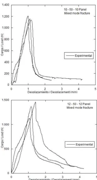
3 EXPERIMENTAL RESULTS
The obtained experimental results are quite stable and repetitive for both testing geometries, as may be seen, for example, in
the load versus displacement curves shown in Figures 7 and 8.
Figure 6: Sandwich panel specimen, under mixed mode
fracture testing. Specimen of 150 mm height.
Figure 7: Fracture experimental results of the
mixed mode fracture.
PPPP
DDDD
D / 4 D / 4D / 4 D / 4 2 D2D2D2D
7 D / 4 7 D / 47 D / 4 7 D / 4 D / 4D / 4D / 4D / 4
D / 2 D / 2D / 2 D / 2
4 . 2 5 D 4 . 2 5 D4 . 2 5 D 4 . 2 5 D
DDDD
PPPP
DDDD
D / 4 D / 4 D / 4 D / 4 7 D / 4
7 D / 4 7 D / 4 7 D / 4 7 D / 4
7 D / 47 D / 4 7 D / 4
D / 2 D / 2 D / 2 D / 2
4 . 2 5 D 4 . 2 5 D 4 . 2 5 D 4 . 2 5 D
3 D / 4 3 D / 43 D / 4 3 D / 4
D / 2 D / 2 D / 2 D / 2
4 NUMERICAL MODEL
The numerical procedure adopted is based on the finite element method. This reproduces the fracture process of sandwich panels of plasterboard and rock wool under mixed loading, by using an embedded cohesive crack based on the strong discontinuity approach [5]. The model has previously been successfully used for the simulation of mixed mode fracture of brickwork masonry by Reyes et al. [6], where a detailed description of the model is collected.
The numerical approach is incorporated in the commercial finite element code ABAQUS©, by means of a user subroutine for the material (UMAT). In summary it can be said that the model uses constant strain triangles which are capable of cracking when a failure criterion is reached by introducing a jump displacement inside, as Figure 9 schematically shows. In this work a Rankine criterion is used.
These finite elements with embedded cracking are used to simulate the mixed mode bending tests, by introducing the mechanical properties of the panels obtained in previous works [7], as summarised in Table 3. For modeling an exponential type of softening curve has been used.
The geometry of the models are adapted to the outline of the Figures 3 and 5, and their dimensions are as shown in Table 2 and Table 4.
Table 3: Mechanical properties of sandwich panels.
Panel GF (N/m) ft (MPa) E (MPa)
Aver. (σ) Aver. (σ) Aver. (σ)
10-50-10 437 (80.01) 1.08 (0.19) 140 (9.20)
10-60-10 919 (142.5) 1.17 (0.14) 113 (13.6)
12-50-12 463 (128.5) 1.13 (0.24) 126 (11.4)
12-60-12 548 (118.3) 1.01 (0.09) 107 (20.1)
Table 4: Mixed Mode Panels (Specimen dimensions)
Panel Height (mm.) Length (mm.)
10-50-10 70 297.5
10-60-10 80 340.0
12-50-12 74 314.5
12-60-12 84 357.0
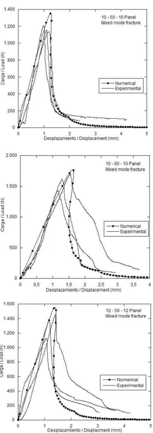
Firstly the numerical model is used to simulate the mixed mode bending tests of the panels described in Table 1. The numerical load versus displacement curves are compared with those obtained in the experimental tests, with a good fit being obtained as that shown in Figure 10.
Figure 8: Size effect. Fracture experimental results
of the mixed mode fracture.
1 y 2 + -x 3 s β n 2 3 1 -+ n
e es
(a) (b)
(c)
Figure 9: Constant strain triangles: a) global
coordinate system x-y and locals coordinate n-t; b) normal and tangential components of the
displacement jump.
Figure10: Experimental records and numerical
prediction of mixed mode fracture test.
Figure 10 (cont.): Experimental records and
numerical prediction of mixed mode fracture test.
Figure 11: Size effect. Experimental records and
numerical prediction of mixed mode fracture test.
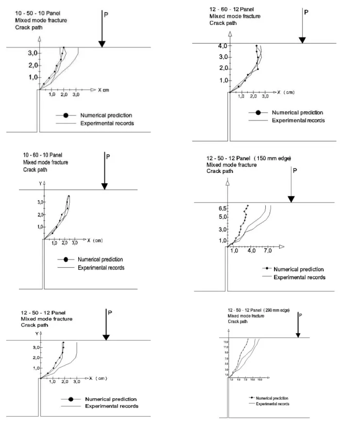
Figure 12: Experimental records and numerical
prediction of mixed mode crack paths.
Figure 13: Finite elements deformed mesh of a
panel sandwich specimen under mixed mode loading conditions.
5 SIZE EFFECT
Figure 14 shows the graph of the size effect, with error bars, corresponding to the values obtained for the different samples with 74, 150 and 290 mm of height.
In the graph the values of the height are parameterised with the characteristic length of the material, Bazant and Planas [8], and the nominal stress with the ultimate stress. The required values were obtained from previous works [7].
Figure 14: Size effect. Specimen of 70 – 150 y
290 mm of height.
6 CONCLUSIONS
The cohesive crack model, implemented in finite elements with an embedded crack, provides a good approximation of the mixed mode fracture behaviour of sandwich panels of
plasterboard and rock wool. The prediction provided by the proposed numerical model adequately reproduces the experimental results, as Figures 7, 10 and 12 show. This procedure could be used to study the limitation of the deflection of slabs to prevent cracking of sandwich panel partitions.
The size effect of this material is appreciable, given the different mechanical properties of the two components of the panel. It is possible to appreciate a change in the mechanical behaviour from which it may be deduced that for small specimens the dominant material is plaster, whereas in the case of the large it is the rock wool.
Given that it uses as input variables the mechanical and resistant properties of the sandwich panel obtained from experimental tests, which are different and separated from the simulated mixed mode fracture tests, the
proposed numerical model is predictive. In this
work the authors have used as input variables the properties measured for the material in previous studies.
ACKNOWLEDGEMENTS
The authors gratefully acknowledge the financial support for the research provided by the Spanish Ministerio de Ciencia e Innovación under grants IPT-42000-2010-31, and DPI2011-24876.
REFERENCES
[1] Ministerio de la Vivienda, “Código Técnico
de la Edificación. Documento Básico: Protección Frente al Ruido”. Madrid
(2006)
[2] Asociación Española de Fabricantes de Ladrillos y Tejas, “Estadísticas del sector”. Madrid (2.010)
[3] Ministerio de la Vivienda, C.S.I.C. Instituto Eduardo Torroja, “Catálogo de elementos
constructivos del Código Técnico de la Edificación”. Madrid (2008)
[4] E.Reyes, M.J.Casati y J.C.Gálvez “Estudio
experimental de la fisuración de la fábrica de ladrillo bajo solicitaciones de tracción y cortante en modelos reducidos”. Materiales
de construcción. (Vol 58, 291, 69-83, Julio-Septiembre 2.008). 0 0,2 0,4 0,6 0,8 1
0 1 2 3 4 5 6 7
ft, n
o m in a l / ft, u lt im a te
[5] Simó, J, Oliver J., Armero F.,“An analysis
strong discontinuities induced by strain softening in rate-independent inelastic solids”. Comput. Mech., (12:277-96, 1993)
[6] Reyes, E., Gálvez, J.C., Casati, M.J., Cendón, D.A., Sancho, J.M., Planas, J.,“An
embedded cohesive crack model for finite element analysis of brickwork masonry fracture”. Engineering Fract. Mech (Vol
76, pag 1930-1944, 2009)
[7] J.A.Alonso, E. Reyes y J.C. Gálvez,
“Caracterización del comportamiento en fractura de paneles sándwich de placa de yeso laminado y lana de roca”. Anales de
mecánica de la fractura. XXVIII Encuentro del grupo español de fractura (Vol 28-I, pag 77-82, 2011)
[8] Z.P., Bazant y J.M., Planas, J.,“Fracture
and size effect in concrete and other quasibrittle materials”. CRC Press LLC