A Reference Model Instantiation to Develop a Methodology from Mechatronic Product Desig: In Wireless Sensor Network Application Edición Única
153
0
0
Texto completo
(2) INSTITUTO TECNOLÓGICO Y DE ESTUDIOS SUPERIORES DE MONTERREY DIVISIÓN DE INGENIERÍA Y ARQUITECTURA PROGRAMA DE GRADUADOS EN INGENIERÍA Los miembros del Comité de Tésis recomendamos que la presente Tésis del Ing. Roberto Cristian Delgado Arcos sea aceptada como requisito parcial para obtener el grado académico de Maestro en Ciencias con especialidad en:. SISTEMAS DE MANUFACTURA COMITÉ DE TESIS. ________________________ Dr. Arturo Molina Gutiérrez ASESOR. __________________________ Dr. Federico Guedea Elizalde SINODAL. _____________________________ MC. Armando Céspedes Mota SINODAL. APROBADO. _______________________________ Dr. Federico Viramontes Brown Director del Programa de Graduados en Ingeniería. Mayo de 2006. II.
(3) Dedicatory. gÉ Åç ÑtÜxÇàá eÉuxÜàÉ tÇw VtÜÅxÇ gÉ Åç ã|yx Uxàç gÉ Åç f|áàxÜ fxÄxÇx g{tÇ~á yÉÜ tÄÄ444. III.
(4) Acknowledgements. Dr. Arturo Molina Gutiérrez Thanks for sharing his knowledge, supporting my master studies at the ITESM and the time dedicated to my thesis work.. Dr. Federico Guedea and MC. Armando Céspedes Thanks for their support as advisors in my thesis work.. Centro de Sistemas Integrados de Manufactura, now, Centro de Innovación en Diseño y Tecnología, and special to Mechatronics Research Center for supporting me in my master studies.. To IECOS and UC Berkeley for all Wireless Sensor Nodes provided To Joaquín, Polox, Choche, Concha, Nico, Nacho, “Los Paisas”, “Los Costeños y sus burritas”, la víbora, tux and all my friends, specially, the active and no-active members from some place called “El Alberge”, thanks for their friendship.. IV.
(5) Summary Currently the process of manufacturing has been changed according to the customer’s requirements. Actual trends in manufacturing, such as mass customization, shorter product life, frequent of changes of design, small inventory restrictions, legal restrictions (energy, environment pollution), etc., presses to companies to employ different technologies in order to be more competitive and efficient. Recently, the industry has been developed some concepts to overcome current currently challenges. For example: process automation (PA), factory automation (FA), flexible manufacturing systems (FMS), reconfigurable manufacturing systems (RMS) etc., but these concepts need some technologies for achieving the best performance and ensuring product quality. Sensors are fundamental devices or systems in the automation process. Sensors and the sensor systems must work with some performance; the performance are based in electrical, electronic and mechanical characteristics (accuracy, repeatability, small size, low power consumption, practical installation, frequency bandwidth, ration noise, linearity, etc.), but of single sensor is not enough for multivariable detection and conversion of industrial variables, because the number of parameters is relatively large. The Wireless Sensor Networks (WSN) have a lot of features that make them attractive such as an instrument of solution for different challenges in the actual industry or factory. This technology can achieve the new requirements in futures aspects of the manufacturing. This thesis proposes an integrated methodology for Mechatronic Product Development using the Wireless Sensor Network technology. The methodology allows to create a mechatronic product from the reference and partial model to a particular model through instantiation. The methodology is based in stages, each stage has activities performed to achieve a result in a specific process. The stages are from product planning to prototyping (product planning, conceptual design, embodiment design and prototyping) and the activities of the design process [(1) Analysis: are oriented to diagnose, define and prepare information, (2) Synthesis: are oriented to put all elements together to produce new effects and to demonstrate that these effects create an overall order. (3) Evaluation: are oriented to test those solutions against the goals and requirements] in each stage. This methodology emphasized in the coupling between each area (mechanical, electronic and software) and the electronic design. The case of study was the development a mechatronic product to demonstrate the usefulness of the methodology. The mechatronic product was an integrated product for monitoring remotely pneumatic pressure in industrial pipelines using commercial WSN, the system developed covered the mechanical design of the attaching system for the sensor. The conditioning of the electrical signal from the sensor and the programming of the sensor capabilities for remote data access and management using real-time operating system called TinyOS. The data gathered from the WSN were displayed in a personal computer (PC). The principal results obtained on this research thesis were: (1) A methodology to develop mechatronics products form the reference and partial model to particular model through instantiation (2) A case study was developed to demonstrate how to use the methodology to develop mechatronics products using Wireless Sensor Networks technology, (3) A mechatronic product for monitoring remotely pneumatic pressure in industrial pipelines with following features: small size, low power consumption, wireless data transmission, “ad- hoc” network, etc.. V.
(6) Some conclusions obtained from this thesis were: (1) Although the concept of measurement physical variables using wireless technologies has been applied, the proposed solutions have not been integrated with the methodology to develop mechatronics products using Wireless Sensor Networks nor the signal conditioning and power management to integrate new Micro-Electro-Mechanical Systems (MEMS) (2) The methodology provides some benefits: fulfills the customers needs, solves some design problems, prevents some failures in design, reduces the time of design, etc. (3) The literature review showed that there are a lot of methodologies to product design. These methodologies do not provide a particular model to mechatronic product or mechatronics product based in wireless sensor network technologies (4). The case of the study helped to identify important areas of further work in power management, data sampling, communications, and software design. (5) The methodology, in this case of study, fulfilled with the objectives, but the correct validation will be based in more case of study.. VI.
(7) Contents. Contents DEDICATORY.................................................................................................................................................. III ACKNOWLEDGEMENTS ...............................................................................................................................IV SUMMARY.......................................................................................................................................................... V CONTENTS ...................................................................................................................................................... VII LIST OF FIGURES............................................................................................................................................. X LIST OF TABLES............................................................................................................................................ XII CHAPTER 1 1.1 1.2 1.3 1.4 1.5. INTRODUCTION.................................................................................................................... 1. BACKGROUND ...................................................................................................................................... 1 RESEARCH JUSTIFICATION ................................................................................................................... 2 OBJECTIVES.......................................................................................................................................... 2 SCOPE .................................................................................................................................................. 2 THESIS ORGANIZATION ........................................................................................................................ 3. CHAPTER 2. LITERATURE REVIEW........................................................................................................ 4. 2.1 NEXT GENERATION MANUFACTURING SYSTEMS ................................................................................. 4 2.2 NEXT GENERATION MANUFACTURING SYSTEMS AND CHALLENGES IN NEXT GENERATION MANUFACTURING SYSTEMS ............................................................................................................................... 5 2.3 RECONFIGURABLE MANUFACTURING SYSTEMS ................................................................................... 6 2.4 MEASUREMENT SYSTEMS .................................................................................................................... 7 2.5 FUNCTIONAL ELEMENTS OF AN INSTRUMENT ....................................................................................... 7 2.6 ACTIVE OR PASSIVE TRANSDUCERS ...................................................................................................... 8 2.7 GENERALIZED PERFORMANCE CHARACTERISTICS ................................................................................ 8 2.7.1 Media transmission......................................................................................................................... 9 2.7.2 Data transmission and instrument connectivity.............................................................................. 9 2.7.3 Cable transmission for analog voltage and current signals ......................................................... 10 2.7.4 Cable transmission for digital data .............................................................................................. 10 2.7.5 Radio Telemetry............................................................................................................................ 10 2.7.6 Signal Condition for Pressure Sensor........................................................................................... 10 2.8 INDUSTRY NETWORK AND WIRELESS TECHNOLOGIES ......................................................................... 12 2.9 WIRELESS COMMUNICATIONS IN INDUSTRY ....................................................................................... 13 2.10 WIRELESS SENSOR NETWORK ............................................................................................................ 14 2.10.1 History ..................................................................................................................................... 14 2.10.2 Description............................................................................................................................... 15 2.10.3 Applications of Wireless Sensor............................................................................................... 17 2.10.4 The challenges for routing data in Wireless Sensor Network .................................................. 18 2.10.5 The requirements for wireless sensor ...................................................................................... 18 2.10.6 Hardware requirements ........................................................................................................... 19 2.10.7 Software for Wireless Sensor Network..................................................................................... 25 2.11 EMBEDDED SYSTEMS ......................................................................................................................... 26 2.12 WIRELESS SENSOR NETWORK IN THE INDUSTRY ................................................................................ 29 2.12.1 Pneumatic Systems................................................................................................................... 29 2.12.2 Machining tools industry ......................................................................................................... 30 2.12.3 Robots Industry ........................................................................................................................ 31 CHAPTER 3. METHODOLOGY PROPOSED.......................................................................................... 34. 3.1 METHODOLOGY DESCRIPTION ............................................................................................................ 34 3.2 PHASE 1, PRODUCT PLANNING: .......................................................................................................... 37 3.2.1 Activities in the Product Planning ................................................................................................ 37 3.3 PHASE 2 CONCEPTUAL DESIGN ........................................................................................................... 38. VII.
(8) Contents 3.3.1 Activities in the Conceptual Design.............................................................................................. 38 3.4 PHASE 3 EMBODIMENT DESIGN PHASE FOR MECHATRONIC PRODUCT ............................................... 39 3.4.1 Mechanical Design ....................................................................................................................... 39 3.4.2 Electronic Design ......................................................................................................................... 39 a b c. Design specifications. ....................................................................................................................................40 Library Development.....................................................................................................................................40 Design Synthesis. ..........................................................................................................................................40. 3.4.3 Software Design............................................................................................................................ 42 3.5 PROTOTYPING .................................................................................................................................... 43 3.5.1 Mechanical Prototype................................................................................................................... 43 CHAPTER 4. CASE OF STUDY.................................................................................................................. 47. 4.1 INTRODUCTION................................................................................................................................... 47 4.2 PRODUCT PLANNING PHASE ............................................................................................................... 47 4.2.1 Product Definition ........................................................................................................................ 47 4.2.2 Project Planning........................................................................................................................... 48 4.2.3 Understanding customers needs. .................................................................................................. 48 4.2.4 Competitive benchmarking Mechatronic Product ........................................................................ 48 4.2.5 Competitive benchmarking Mechanical Product.......................................................................... 49 4.2.6 Competitive benchmarking Electronic Product............................................................................ 49 4.2.7 Patent Analysis ............................................................................................................................. 50 4.2.8 Market Requirements.................................................................................................................... 52 4.2.9 Technical requirements and characteristics ................................................................................. 53 4.2.10 Tollgates in Product Planning Phase ...................................................................................... 53 4.3 CONCEPTUAL DESIGN PHASE ............................................................................................................. 54 4.3.1 Functional Analysis for Electronic Design................................................................................... 54 4.3.2 Functional Analysis for Mechanical Design................................................................................. 55 4.3.3 Functional Analysis for Software Design ..................................................................................... 55 4.3.4 Functional Analysis for Mechatronic Design (Coupling)............................................................. 56 4.3.5 Product Process Specifications .................................................................................................... 57 4.3.6 Target and Constraints ................................................................................................................. 57 4.3.7 Tollgates in Conceptual Design Phase ......................................................................................... 57 4.4 EMBODIMENT REQUIREMENTS ELECTRONIC DESIGN ......................................................................... 58 4.4.1 Coupling Between Each System (Mechanical, Electronic and Software)..................................... 58 4.4.2 Behavioral or functional representation of the systems................................................................ 58 4.4.3 Signal Condition Pressure Sensor and Model for the sensor ....................................................... 59 4.4.4 Virtual Construction ..................................................................................................................... 59 4.4.5 Bills of Materials .......................................................................................................................... 60 4.4.6 Drawings ...................................................................................................................................... 61 4.4.7 Tollgates in Embodiment requirements (electronic design) ......................................................... 62 4.5 EMBODIMENT REQUIREMENTS MECHANICAL DESIGN ........................................................................ 62 4.5.1 Embodiment Requirements ........................................................................................................... 62 4.5.2 Mechanical Dimensions and Assembly......................................................................................... 63 4.5.3 Tollgates in Product Mechanic Design......................................................................................... 64 4.6 EMBODIMENT REQUIREMENTS SOFTWARE DESIGN ............................................................................ 65 4.6.1 Case Diagrams ............................................................................................................................. 65 4.6.2 Interaction diagrams .................................................................................................................... 65 4.6.3 Class diagrams ............................................................................................................................. 66 4.6.4 Tollgates in Software Design........................................................................................................ 67 4.7 PROTOTYPE ........................................................................................................................................ 67 4.7.1 Tollgates in Prototyping ............................................................................................................... 70 CHAPTER 5 5.1 5.2 5.3. RESULTS AND CONCLUSIONS ....................................................................................... 72. RESULTS............................................................................................................................................. 72 CONCLUSIONS .................................................................................................................................... 72 FURTHER WORK ................................................................................................................................. 73. VIII.
(9) Contents CHAPTER 6. REFERENCES....................................................................................................................... 74. CHAPTER 7. APPENDIX............................................................................................................................. 77. APPENDIX A1 APPENDIX A2 APPENDIX A3. PRODUCT PLANNING ............................................................................................................ 78 CONCEPTUAL DESIGN .......................................................................................................... 95 EMBODIMENT DESIGN PHASE FOR MECHATRONIC PRODUC .............................................. 109. IX.
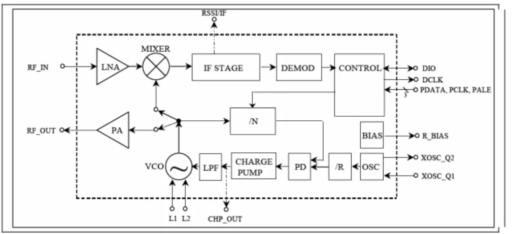
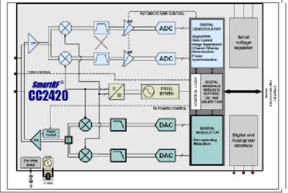
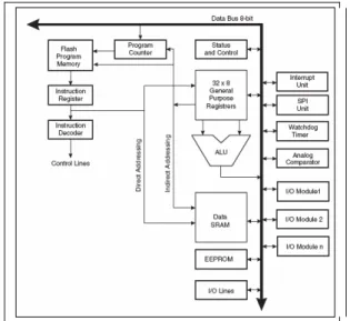
(10) List of Figures. List of Figures Figure 1. Functional Elements of a measurement system..........................................................7 Figure 2 General Signal Condition for pressure sensor ...........................................................11 Figure 3 General concept of Wireless Sensor Network...........................................................16 Figure 4 General block diagram for TR1000...........................................................................21 Figure 5 General diagram block CC1000 ................................................................................21 Figure 6 General block diagram for CC2420 ..........................................................................22 Figure 7. Harvard Architecture for Microcontroller. ...............................................................23 Figure 8 RISC Architecture for Microcontroller .....................................................................23 Figure 9 General block diagram for Atmel microcontroller. ...................................................24 Figure 10 Von-Neumann Architecture ....................................................................................24 Figure 11 Components for multi-hop sensing application.......................................................28 Figure 12. Wireless Sensor Network and lay out factory distribution.....................................29 Figure 13 Temperature, vibration and sound sensor network in machining tool. ...................31 Figure 14 Wireless Sensor Network in Machining Tools........................................................31 Figure 15 Wireless Sensor Network in Robots........................................................................32 Figure 16 Particular Model through Instantiation of Mechatronics Products..........................34 Figure 17 Reference Model for Integrated Product, Process and Facility Development (IPPDM) (Aca Sánchez, 2004) ................................................................................................35 Figure 18 Framework and methodology to developing mechatronic products. ......................36 Figure 19 Particular model from partial model........................................................................37 Figure 20. General block diagrams for electronic system. ......................................................39 Figure 21 Relationship between Next Generation Manufacturing System, Wireless Sensor Network Technology and Methodology for Develop new Products. ......................................44 Figure 22 Gantt chart for project planning ..............................................................................48 Figure 23 General sketch from the competitive benchmarking in mechatronic products .......50 Figure 24 Possible solutions gotten from the Patent Analysis.................................................52 Figure 25 Functional Analysis for Electronic Design..............................................................55 Figure 26 Functional Analysis for Mechanical Design ...........................................................55 Figure 27 Functional Analysis for Software Design................................................................55 Figure 28 Functional Analysis in Coupling .............................................................................56 Figure 29 Tollgates in Conceptual Design Phase ....................................................................57 Figure 30 General elements selected from functional decomposition and Morphological Matrix.......................................................................................................................................59 Figure 31 Electrical model for the sensor a) Ideal b) with electrical noise .............................60 Figure 32 Electrical circuit for filtering the electrical noise ....................................................60 Figure 33 Electrical circuit for power management ................................................................60 Figure 34 General dimension for condition signal and filtering circuit...................................61 Figure 35 General elements selected after of electronic design activities ...............................62 Figure 36 General elements selected after of mechanical design activities.............................63 Figure 37 Mechanical dimensions and assembly for Mechanical Design...............................64 Figure 38 Robustness diagram for monitoring pressure using TinyOS...................................66 Figure 39 General elements selected after of software design activities .................................67 Figure 40 Mechatronic Prototype ............................................................................................68. X.
(11) List of Figures Figure 41 Electronic Prototype ................................................................................................69 Figure 42 Mechanical and Electronic joined Prototype...........................................................69 Figure 43 Layout of sensor deployment in the CETEC’s cellar..............................................70 Figure 44 Pneumatic pressure was displayed in real time using the application “oscilloscope” ..................................................................................................................................................70 Figure 45 Phase 1 Formulate factions through task listening ..................................................99 Figure 46 Case diagram for monitoring pressure remotely ...................................................124 Figure 47 Robustness diagram for monitoring pressure using TinyOS.................................125 Figure 48 Interaction diagrams for monitoring pressure using TinyOS ................................127 Figure 49 Class diagrams for monitoring pressure using TinyOS.........................................128. XI.
(12) List of Tables. List of Tables Table 1. Major changes in manufacturing systems....................................................................4 Table 2 Tendencies in manufacturing from 80’s to present ......................................................5 Table 3.Table Features and Concept in Reconfigurable Manufacturing Systems.....................6 Table 4. Main challenges in RMS..............................................................................................6 Table 5 Common transducers and their properties ....................................................................8 Table 6 Characteristics of Wireless Networks.........................................................................13 Table 7 Projects in Wireless Sensor Network..........................................................................15 Table 8 Berkeley motes and radio description.........................................................................20 Table 9 Berkeley mote and Microcontroller............................................................................22 Table 10 sensor market digital and analog ..............................................................................25 Table 11 Open source and no open source RTOS ...................................................................26 Table 12 Major research in Architecture for Wireless Sensor Network (T. Liu & Martonosi, 2003)(H. Liu et al., 2005) ........................................................................................................27 Table 13 Wireless Sensor technology capabilities and the Next Generation Manufacturing Technology ..............................................................................................................................33 Table 14 Activities summarized in product planning phase....................................................38 Table 15 Activities summarized in the Conceptual Design Phase. .........................................38 Table 16 Activities summarized in the Mechanical Design ....................................................39 Table 17 Levels of abstraction and representation ..................................................................41 Table 18 Levels of abstraction and synthesis ..........................................................................41 Table 19 Activities summarized in the Electronic Design.......................................................41 Table 20 Activities summarized in the Software Design phase ..............................................42 Table 21 Activities for rapid mechatronic product development and manufacturing .............45 Table 22 Activities for Product Planning Phase ......................................................................47 Table 23 Information about the competitive benchmarking....................................................49 Table 24 Competitive benchmarking in Mechanical Product..................................................49 Table 25 Competitive benchmarking in Electronic Product....................................................49 Table 26 Ideas generated for competitive benchmarking ........................................................50 Table 27 Patents used in Mechanical Design ..........................................................................51 Table 28 Patent Analyzed ........................................................................................................51 Table 29 Ideas generated for patent analysis ...........................................................................51 Table 30 Format for interview in market requirements. ..........................................................53 Table 31 Tollgates in Product Planning Phase ........................................................................53 Table 32 Activities for Conceptual Design Phase ...................................................................54 Table 33 Activities for Functional Decomposition..................................................................54 Table 34 Targets and constrains for monitoring pneumatic pressure ......................................57 Table 35 Coupling between each system (mechanical, electronic and software)....................58 Table 36 the bill of materials for building the coupling circuit (sensor and MOTE) ..............61 Table 37 Tollgates in Embodiment Requirements Phase (Electronic Design)........................62 Table 38 Embodiment requirements for mechatronic product ................................................63 Table 39 Tollgates in Embodiment Requirements Phase (Mechanical Design)......................64 Table 40 Tollgates in Embodiment Requirements Phase (Software Design)..........................67 Table 41 Tollgates in Prototyping............................................................................................71. XII.
(13) Chapter 1. Chapter 1 1.1. Introduction. Background A new competitive environment for industrial products and services, pressures and regulatory issues. (prices, political, environment etc.), are emerging and are forcing a change in the way manufacturing enterprises are managed. Competitive advantages in the new global economy will belong to manufacturing enterprises, which are capable of responding rapidly to changing market, the demand of high quality products, continuous innovation, and highly customized products. Operating new competitive firms is becoming more difficult as product variety and options increase, product complexity increases, product life cycles shrink, and profit margins decrease. In addition, the capital costs of manufacturing technologies are extremely high. These factors impose high productivity levels for labor and manufacturing facilities. There is also the need to create the next generation of manufacturing systems (NGMS) with higher levels of flexibility, allowing these systems to respond to very dynamic market demands. The following technological areas have been defined to be core for the success of next generation manufacturing: •. Adaptable, integrated equipment, processes, and systems that can be readily reconfigured.. •. Manufacturing processes that minimize waste production and energy consumption.. •. Innovative processes to design and manufacture new materials and components.. •. Biotechnology for manufacturing.. •. System synthesis, modeling, and simulation for all manufacturing operations.. •. Technologies that can convert information into knowledge for effective decision making.. •. Product and process design methods that address a broad range of product requirements.. •. Enhanced human-machine interfaces.. •. Educational and training methods that would enable rapid assimilation of knowledge.. •. Software for intelligent systems for collaboration.. There are some organizations working in these challenges; European Commission, The future of Manufacturing in Europe 2015-2020; DTI and EPSRC, industry needs in UK (National Research Council . Board on Manufacturing and Engineering Design. Committee on Visionary Manufacturing Challenges & NetLibrary, 1998b). 1.
(14) Chapter 1. 1.2. Research Justification Wireless Sensor Networks (WSN) is a new technology with some capabilities that can help to improve. some industrial process. This technology, in manufacturing process could be able to: measure, indicate, record quantities or physical properties as light, temperatures, sound, acceleration etc. Today, WSN are used in environment monitoring, inventory tracking, machine mounting sensing, building climate monitoring, security, identification, medical monitoring etc., WSN has the characteristics of being smaller, more efficient, less expensive, and more versatile that other network solutions, but they have an inconvenient, this technology is an experimental network. Some industries such as Sensicast Inc., Millenialnet Inc., and Smartdust Inc. have been developed applications for WSN, the applications developed were done for environment applications. WSN uses devices called Micro-Electro-Mechanical Systems (MEMS). MEMS in the global market are showing great growth, and this growing expects to increase even more (up to 250% at the end of 2005) for the measurement and control market than in the automotive market (50% growth) (Jean-Michel, 2004). The development of some products or prototype for manufacturing process needs a methodology to achieve the desired objective, a product that satisfies the needs of the customers (time, cost, etc). The mechatronics products in the industry has been grown quickly, therefore a methodology for developing mechatronics products using Wireless Sensor Network will have great potential.. 1.3. Objectives The objectives of the present thesis are: •. Develop integrated methodology for Mechatronic Product Development using the Wireless Sensor Network technology; the methodology allows to create a mechatronic product from the Reference Model for Integrated Product, Process and Facility Development developed by (Aca Sánchez, 2004) and the partial model developed by (Farias Moreno, 2003) through instantiation. The new model (a particular model) will be developed for the electronic subsystem.. •. Demonstrate using case study how to use the methodology to develop mechatronics products using Wireless Sensor Networks,. •. A mechatronic product for monitoring remotely pneumatic pressure in industrial pipelines with the following features: small size, low power consumption, wireless data transmission, “adhoc” network.. 1.4. Scope The development of a product is a set of activities to bring from the idea to a final product, according to. (Farias Moreno, 2003); mechatronics is a methodology to design products that exhibits fast, precise performance. These characteristics can be achieved by considering not only the mechanical design but also the use of servo controls, sensors, and electronics. This thesis covers an integrated methodology for Mechatronic Product Development using the Wireless Sensor Network technology; the methodology allows create a mechatronic. 2.
(15) Chapter 1 product form the reference and partial model to particular model through instantiation, the methodology is based in stages, an case study to demonstrate how to use the methodology to develop mechatronics products using Wireless Sensor Networks, a mechatronic product for monitoring remotely pneumatic pressure in industrial pipelines with following features: small size, low power consumption, wireless data transmission, “ad- hoc” network, etc.. 1.5. Thesis Organization The research realized is organized in four chapters described below Chapter 2: In this chapter a literature review analysis is done about the Next Generation Manufacturing. Systems (NGMS), Reconfigurable Manufacturing Systems (RMS) and their 8 principal challenges. Measurements Systems are important tools to achieve the main goals in RMS and NGMS; the concepts of elements, transducer, characteristics of sensors, media transmission, etc. are covered. The concept of Wireless Sensor Networks (WSN) such as history, description, applications, requirements, are covered. Chapter 3: This chapter covers the methodology proposed, this methodology was obtained from the reference model and the partial model through instantiation. The four stages are described (Product Planning, Conceptual Design, Embodiment Requirement and Prototyping) and the design activities (analysis, synthesis and evaluation) are defined. Chapter 4: This chapter describes the case of study developed for monitoring remotely pneumatic pressure in an industrial pipeline system using the methodology proposed. The design covers the stage of Product Planning (Product Definition, Project Planning, Competitive Benchmarking, and Patent Analysis), Conceptual Design (Functional Analysis, Targets and Constrains), Embodiment Requirements (Coupling between each Systems Behavioral representation, Signal Condition Pressure Sensor, Electrical and mathematical model of Components, Virtual Construction Simulation and Prototype, Virtual Assembly, etc) and prototype. Chapter 5: This chapter describes the main results, the conclusions gotten after the case of study and future work to be developed. Chapter 6: Reference. 3.
(16) Chapter 2. Chapter 2. Literature Review. The purpose of this chapter is provide information about the new tendencies in manufacturing systems, a description about measurement system, Wireless Sensor Network capabilities and how this technology can help to achieve the Next Generation Manufacturing Systems concept.. 2.1. Next Generation Manufacturing Systems What is manufacturing? The word manufacturing, according with Merriam Webster dictionary, meaning,. “To make into a product suitable for use” “to make from raw material by hand or by machinery” “is the process of converting raw materials into products. It compasses: the design, the selection of raw materials and the sequence of process through witch the product will be manufactured.” (Kalpakjian, 2001). The manufacturing has been changed since early 18th century but from 20,000 B.C. some product was “manufactured” by the first human, the past, present and future in manufacturing is showing in the Table 1. The manufacturing systems exist in different types, for mass production, lean production, flexible and reconfigurable, and it’s depending on the objective pursuit of the enterprise and the competitive market advantages. The factors that made possible the fast evolution of manufacturing systems and development of new tools and techniques for improved processes were determinant in the creation of new enterprises. From early 70s were the emphasis was on mass production using dedicated lines for custom parts, passing to the 80s were the invention of the CNC changed to a revolutionary industry, and improved the product quality and time production, introducing the just-in-time (JIT), the lean manufacturing and total quality management (TQM), until the development of Flexible Manufacturing Systems (FMS) in which the economic objective is to make possible the cost-effective manufacture of numerous types of parts than may change over time, on the same system at the required volume and quality (Setchi & Lagos, 2004). In the 90s, the management of information systems, the progress of software applications, the improvement in communication systems and the vast use of computers, have led to a fast progress in the manufacturing systems. th. Table 1. Major changes in manufacturing systems th. th. th. Early 18 Century. 19 Century. 20 Century. 21 Century. A person with an anvil hammer. Steam powered machinery. CAX (Computer Aided X: Design, Planning, Manufacturing). System wide networks and information. Poorly understood process Craftspeople Cottage Industry. Improved understanding of processes Factory conditions in cities. Limit process models using closed loop control Increase factory automation. Robust process intelligent control. and. Global enterprises and virtual manufacturing corporations.. Since 1980 to the manufacturing has been changed quickly, this change was done according to the customer’s needs and intense competition. There are some concepts, tools and philosophies created to improve the manufacturing process, and these trends are showed in the Table 2 (Wright, 2001).. 4.
(17) Chapter 2 Table 2 Tendencies in manufacturing from 80’s to present Year. Concept. Improve. <1975. Computer Integrated Manufacturing (CIM). Lower labor. 1980. Robotics and Flexible Manufacturing Systems (FMS). Lower labor, flexibility. 1983. Artificial Intelligence. 1985. Quality assurance manufacture. 1988. Open manufacturing. 1994. Agile manufacturing. Lower labor, flexibility, Intelligence quality, reduced WIP, reduced lead time, rapid response, reconfigurability for new products. 2000. Internet based manufacturing. Lower labor, flexibility, Intelligence quality, reduced WIP, reduced lead time, rapid response, reconfigurability, Networked CAD/CAM, collaborative design. Future. 2.2. Lower labor, flexibility, Intelligence and. lean. architecture. Lower labor, flexibility, Intelligence quality Lower labor, flexibility, Intelligence quality, reduced WIP, reduced lead time, rapid response. NGMS. ???. Next Generation Manufacturing Systems and Challenges in Next Generation Manufacturing Systems There are some visions about what is the trend or philosophy to follow in manufacturing systems. In. 1998 the Committee on Visionary Manufacturing Challenges visualized the trend and challenges in manufacturing for 2020. The objectives were: create a vision of competitive environment for manufacturing and the nature of manufacturing factory or enterprise, determine the major challenges for future manufacturing and identify the key technologies for achieving these challenges Table 3 shows these conclusions (National Research Council . Board on Manufacturing and Engineering Design. Committee on Visionary Manufacturing Challenges & NetLibrary, 1998a).. Table 3 Next Generation Manufacturing Systems, Concepts and Vision CONCEPT. Next Generation Manufacturing System. Challenge 1. Information technology. The knowledge exchanged must enable decisions based on the exchange This technology will permit the recipient to convert diverse sources of information into knowledge that can be readily used. Enterprise modeling and simulation. The technology is essential to combining information from many sources into a consistent description of the enterprise and its operations It will enable individuals to access the information and knowledge within the enterprise's systems. Machine-human interfaces Challenge 2. Challenge 3. VISION. Control and Communication Concepts. Adaptable and reconfigurable systems Collaboration Technology, Teleconferencing, Telecontrol, Telepresence System Security. It will require flexible sensors Reconfiguration of communications and control systems will rely on a common programming and control architecture, as well as ''flexible" and "adaptive" software that does not require reprogramming but does provide operators with sufficient real-time information about the process to allow effective intervention, troubleshooting, and control. It will require system architectures and algorithms and methodologies for acquiring information and converting it into immediately usable knowledge. As jobs and factories are distributed around the globe, real-time information technology will be the most effective means of collaboration. They will need efficient and foolproof security systems to protect data, information, and knowledge, which will be the lifeblood of the industrial enterprise.. 5.
(18) Chapter 2 Automatic Sensors and Actuators for Process and Equipment Control Reduced Energy Consumption Adaptable and reconfigurable systems Adaptable and reconfigurable systems. Challenge 4 Challenge 5 Challenge 6. Improved methodologies. 2.3. design. Processes and equipment will have to be tightly controlled to ensure high quality, low cost output with minimum waste. It must always be to produce no waste of any kind, to consume the minimum amount of energy, and to do both economically. Manufacturing, business processes, and manufacturing systems will be rapidly reconfigurable. It will make possible programmable equipment, processes, and systems that can be used to create a broad range of products rapidly and with minimal changeover costs. It will provide new design methodologies that can be quickly adapted to accommodate major changes in requirements.. Reconfigurable Manufacturing Systems Reconfigurable Manufacturing System (RMS) is a new class of manufacturing system and it is a new. cost-effective response to the market requirements. A RMS is designed for rapid adjustment in its structure, including software and hardware, in order to quickly adjust production capacity and functionality within a part family. The reconfigurability is the ability to repeatedly changes and rearranges the components of a system in a cost-effective way, manufacturing process has a lot paradigms, each paradigm has different objectives, which were defined by the market requirements. There are tree main groups of RMS, dedicated manufacturing systems (DMS), cellular manufacturing systems (CMS), flexible manufacturing systems (FMS).The reconfiguration of a RMS relied on the system design combined with the simultaneous design of open-architecture reconfigurable controllers with reconfigurable modular machines. The key characteristics of a RMS are listed in the Table 3: (Setchi & Lagos, 2004). Table 3.Table Features and Concept in Reconfigurable Manufacturing Systems Features. Concept. Integrability. Interfaces between different modules and sub-modules and the interoperate with each other. Modularity. Describe the use of common units to create products variants. Customization. Ability of latter to be customized in terms of flexibility and control. Convertibility. Short conversion times between different production batches.. Diagnosability. Detecting and identify the causes of abnormal behavior.. RMS have different challenges, the main challenges are showed in the Table 4. Table 4. Main challenges in RMS Challenges. Concept. Product variability. Need for variety of products types and capacities. Responsiveness. Rapid response to changing market requirements.. Non-obsolescence. Enable the adoption of new advances in technology. Cost-effectiveness. Installing the required functionality only when and where it’s in needed. Reliability. Compatibility with future manufacturing systems. Simplicity. Standardization.. 6.
(19) Chapter 2. 2.4. Measurement Systems According to the current and futures challenges in manufacturing systems, the measurement systems. can help to achieve the NGMS concepts, for example: information technology, machine-human interfaces, control and communication concepts, adaptable and reconfigurable systems, automatic sensors and actuators for process and equipment control could need the measurement systems capabilities to solve or improve some problems or performance. Measurement systems include all components (hardware and software) to lead measure variable to process data, every application of sense or measurement can be classified in two types of measurements applications. Monitoring of processes and operations, this system is used to keep and track some physical quantities. Control of processes and operations, these systems can controller a specific variable, or variables with a desired valued, the difference between the desire value and current value (error) can be manipulated with a controller then all feed back control system will have at least one measuring device. The measurement systems are elements of instrumentation field; the industrial instrument is equipment used in production processes in industry which indicates and or records quantities or physical properties (measuring /controlling). (Senbon & Hanabuchi, 1991).. 2.5. Functional elements of an Instrument The general model in an instrument is showing in the Figure 1, the primary sensing element: it’s the. device that receives energy from the environment or medium to be measurement and produces an output depending of measured quantity. All sensing elements extract some energy from the measurement environment or medium and energy is distributing through the instrument. Variable conversion elements: This element converts the original signal measured in the environment or medium by the primary sensing element, to another more suitable variable while preserving information contended in the original signal. Variable manipulation elements: The instruments need that a signal represented by some physical variables be manipulated in some way. The manipulation word means a changing in the numerical value according to some rules, for example, the input can be multiplied, amplified, etc, the element that performs such a function is called variable manipulation element.. Figure 1. Functional Elements of a measurement system.. 7.
(20) Chapter 2 Data transmission elements: This element is a medium for send the information, and it may be a shaft and bearing or a telemetry systems. Data storage/playback: the main functions are recording and sending the desired information. Data presentation element: the main functions of this element is the simple indication for analysis and monitoring. 2.6. Active or passive transducers Transducer, in some literature, is a device that converts energy. A component whose output energy is. supplied almost entirely by its input signal is called passive transducer. The input and output signal can be transformed or be of the same form of energy, mechanical to mechanical, mechanical to electrical, Active transducer this device or devices must has an auxiliary energy source which provides the major part of the output power, the input signal almost always is an insignificant portion of the output signal.. 2.7. Generalized performance characteristics There are some performances characteristics in measurement systems according to the input signal,. Static Characteristics are used to measure quantities that are constant or vary only quite slowly. Static Calibration, Measured value vs. True Value, Static Sensitivity, Linearity, Threshold, Resolution, Hysteresis, Dead Space, Span, Loading effects, and others, are some static characteristics in the measurement systems. The dynamic characteristics are used when the quantities varying rapidly, these characteristics are: first order and second order (step response, ramp response, frequency response, Impulse response) dead time, response to a periodic input, transient input, etc. Table 5 summaries common transducers and their properties.. Table 5 Common transducers and their properties PHYSICAL VARIABLE Motion and dimensional measurement. DEVICE. CHARACTERISTICS. Resistive potentiometer. Linearity, Repeatability, Resolution, Accuracy, Rotation life, Element type, terminal type, Bushing Type, Input resistance, Power rating,, Maximum Input Voltages, Output signal, Resistance Range Enclosure, Operating temperature, Vibration, Output Signal: Voltage divider, incremental encoder, 0..10 V, 4-20 mA, RS232, Device net, CANBUS, (www.celesco.com, www.honeywell.com, ). Trimmers. Encoders. Encoder type, Pulse per revolution, Operation Speed, Dome switch, repeatability, Accuracy, maximum velocity, scale size, dimension, http://www.optra.com. Ultrasonic. Analog output, voltage output, current output, deviceNet, CAN bus, resolution, housing, range. http://www.mtssensors.com. Electro-optical devices. Sensitivity, linearity, reflectivity measurement, operating range, resolution, frequency, range, sensitivity, resolution, data format, measurement signal, reference signal, laser source, semiconductor source http://www.philtec.com/, http://www.zygo.com, http://www.udt.com. Synchros Resolvers. and. Hall effect. Resistive gage Linear. Input voltage, angular range, increments, steps, accuracy, readout, nominal frequency, , output, ,resolution, Insolated inputs and outputs, http://www.tucker.com Supply voltage, supply current, Output current, output voltage, sampling rate, bandwidth, step response, offset, range of sensitivity, output resistance, electrical angle, electrical output range, load life, high and low temperature operation. http://www.vishay.com. Strain. Operating temperature, compensation range, bonding adhesive, material backing, materials element, strain limit, resistance, fatigue life, dimensions, type, applicable specimen, , http://www.straingage.com. variable. Size, diameter, ranges, operating temperature, Enclosure, Input voltage, Input. 8.
(21) Chapter 2 Differential transformers (LVDT). frequency, linearity error, repeatability error, hysteresis error, coefficient of sensitivity, vibration tolerance, primary impedance, sensitivity. http://www.macrosensors.com/index.html. Capacitance. Range, Scale factor (um per volt), noise, thermal stability, axis, resonant frequency, response, material, size, resonant frequency. http://www.queensgate.com/. Acceleration. Accelerometers. Output voltage, Output signal, , frequency range, Mounting, connection, temperature range, Transverse sensitivity, amplitude linearity, output impedance, http://www.cecvp.com/, www.analog.com. Pressure and sound Measurement. Pressure gauge. Range, mount, accuracy, power, enclosure, media compatibility, process connection, output, 4-20 mA, 1-5VDC, relay output, sensitivity, natural frequency, operation range frequency, acceleration sensitivity, absolute, differential, hysteresis, supply voltage, rise time, output polarity, http://www.meriam.com, http://www.kistler.com, http://www.pcb.com/. Bimetallic Thermometer. Size, Accuracy, Ranges, connection, enclosure. http://www.dresserinstruments.com/. Thermocouples. Type, size, output voltage, material, enclosure, Bare wire, Cable assemblies, ceramic insulator, conventional, eroding, fast response, high temperature. www.omega.com http://www.nanmac.com. RTD. Temperature coefficient, total error, voltage output, power supply, temperature range, package, operating temperature. www.analog.com. Thermistor. Resistance, range, time constant, dissipation constant, maximum power, stability. www.ysi.com. Temperature. 2.7.1. Media transmission The information provided by a basic measurement device must be the processed or conditioned to be. presented to observed, storage in the data record or measure the variable controller in the feedback control systems. The processing information should be amplified, filtered, integrated, differentiated, added, subtracted, compensated, modulated or demodulated, according to the systems needs. The tasks listed before can achieve using hardware or software, the option for software solution can be achieve using algorithms for filtering, but, the amplification can be achieve using specific hardware. The devices used for this task are: •. Amplifiers: The electrical signals provides by the transducers are too low for transmit o for processing by some electrical devices, for example microcontrollers or microprocessors. Therefore, an important part of the measurement systems are the amplifiers. There are a wide range of amplifiers, and the most common are: Operational Amplifier, Instrumentation Amplifier, Transconductance and transimpedance amplifiers, carriers’ amplifiers, etc.. •. Filters: The electrical signal provided by the transducer, some times, has a lot of electrical components without information, this information is not desired. It’s called electrical noise and must be cleaned. The electrical filter is the device that can be used to select the frequency desired, the most common filters are: Analog and digital, active and passive, Low pass, highpass filter, band-pass filter, band rejection.. 2.7.2. Data transmission and instrument connectivity When the components of the measurement systems are placed far away from each other (primary. sensing, variable conversion, variable manipulation and the data presentation or storage), it is necessary to transmit this information by some communication channel.. 9.
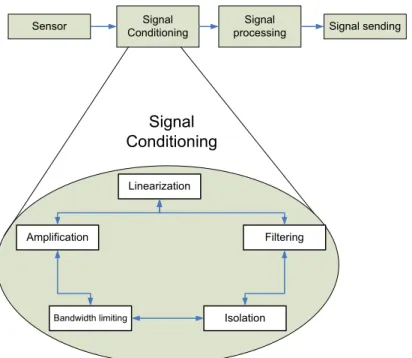
(22) Chapter 2 There are some medium transmissions for the data, for example: cable, fiber optics, radio telemetry, pneumatic. The selection of the transmission medium depends on the signals properties.. 2.7.3. Cable transmission for analog voltage and current signals The wire is the most common medium used to transmit analog voltage or signal from one place to. another, This medium is cheaper than others mediums but has some disadvantages: the cable has an electrical resistance, and this resistance is proportional to the length of the cable. This medium has other electrical parameters that can affect the quality of transmission (capacitance between the wires). The capacitance is affected by the frequency. Typical resistance per foot might be 0.01 ohm and 30 pF/ft. This medium, in the industry, is called “A hard wire”. This data transmission technique can be used to measurement the output of transmitters given in mill volt (thermocouple, RTD, frequency, potentiometer), used a current loop (usually from 4 to 20 mA), a zero input signal produce 4 mA, full scale produced 20 mA, this technique is compatible with HART field protocol (Highway-Addressable Remote Transducer), the HART devices use FSK (Frequency Shift keying) as transmission method.. 2.7.4. Cable transmission for digital data When the distance between the elements in the measurement systems is long, the analog signals tend. to be altered (attenuation, electrical noise, etc.) by the characteristics of transmission lines. The conversions from analog to digital signals transmit them and reconverted to analog should be considered, the rate of transmission in this systems are: ASCII RS-232 9600 Bd, IEEE-488 (GBIB) 2Mbits/s, etc. These digital signals can be transmitted by optical fiber; the advantages of optical fiber are immunity to electronic interference and security.. 2.7.5. Radio Telemetry Telemetry means measurement at distance, this medium is used when it is not possible or desirable to. make the interconnecting with wires. The radio telemetry can be uses in very short distances or when the devices under measuring are moving. The radio telemetry systems use two kinds of systems: FM/FM radio telemetry and digital telemetry (PCM/FM). The FM/FM systems separate the different signals in channels and giving them different frequency ranges; this is called frequency-division multiplexing (FDM) the digital transmission use the pulse code modulation (PCM/FM) to transmit the desired signal (Doebelin, 2004). 2.7.6. Signal Condition for Pressure Sensor. A signal conditioning circuit consists of a circuit to connect an analog sensor to a digital acquisition. system. The circuit has the function shows in the Figure 2. The linearization can be performed digitally, but the amplification and filtering need analog requirements.. 10.
(23) Chapter 2 Signal Conditioning. Sensor. Signal processing. Signal sending. Signal Conditioning Linearization. Amplification. Bandwidth limiting. Filtering. Isolation. Figure 2 General Signal Condition for pressure sensor Linearization/Compensation The output characteristic of a pressure sensor depends of the type of manufacturer. The ideal response is a linear relation between pressure and voltage but the pressure variation and the sensor’s output are similar a curve with a shape that is near to a straight line. The sensor has others parameters as hysteresis and repeatability, these errors can degrade the accuracy of most pressure sensors: Hysteresis error: Sensor output is different for a given pressure when the pressure changes from a higher or lower pressure Repeatability errors: Gain variations between two measurements The environmental factors, as the temperature, humidity, and time can also adversely affect sensor accuracy. The temperature influences the output signal of pressure sensors. The compensation of temperature can be achieved using an electronic circuit, or algorithms. Some commercial sensor has the capability for compensate the temperature effects. Amplification All analog-to-digital converters (ADCs) are limited in their input voltage range for operation. The pressure sensor output signals are usually in the mill volt range and it must be amplified to a point where the signal voltage falls within the input voltage range of the ADC. This function, currently, are done by some electrical devices called Instrumentation amplifiers (in-amps). Bandwidth Limiting Every analog-to-digital interface has frequency constraints. As provided by Nyquist, the highest allowable frequency component in an analog signal before sampling with an ADC is less than or equal to one-half the sampling frequency. The low-pass filter is used almost always in an ADC to remove the higher frequency. 11.
(24) Chapter 2 components that are present in most analog signals. The lower ranges of the signal sensor are more susceptible to electrical noise from several potential sources (motors, power supplies, RFI, etc). The ADC architecture also influences filter requirements. The filter implementation can be achieve with passive or active, analog or digital filter (for example. an operational amplifier, an Resistor-Capacitor (RC). network or only a single capacitor, which provides a first-order low-pass filter function).. 2.8. Industry network and wireless technologies The wireless technology has been developed from the 1920’s when it was used like another alternative. to send telegrams, later like radio (also known like walkie-talkie), to develop services of digital communication that are offered nowadays. In the last years the use of wireless technology has seen a fast growth, due to the increase of requirements (Morel G., Panetto H., Zaremba M-.B., Mayer F., 2003) of telecommunications, data transfer and IT devices in companies, the educative area and homes. These requirements are mentioned by Novel Networks: •. Great communication speed. •. Shared access to files, data/knowledge bases. •. Exchange of picture, voice – multimedia applications. •. On line/real-time access. •. Access for anybody, from anywhere, at any time, -mobility. •. Reliable secure exchange of information. •. Intelligent user interfaces. •. Easy and cheap installation. But all of these requirements have not been implemented in one type of network; nevertheless there are networks that fulfill some of these characteristics depending on the application. Within the wireless technology, different platforms exist (National Research Council . Board on Manufacturing and Engineering Design. Committee on Visionary Manufacturing Challenges & NetLibrary, 1998a) that are currently in use and their usage is limited depending on the application. A structured overview of the different wireless technologies is showing in Table 6.. 12.
(25) Chapter 2 Table 6 Characteristics of Wireless Networks Wireless network type Satellite. Operation frequency 2170–2200 MHz. Data rate. Operation range. Different (9.6 kbps - 2 Mbps). Main characteristics. Satellite coverage. Relative availability. high. Cellular coverage. Reach, quality, low cost. cost,. WWAN GSM. 824-1880 MHz. 9.6 (EDGE). 3G/UMTS. 1755-2200 MHz. 2.4 Mbps. Cellular coverage. Speed, big attachments. iMode (3G/ FOMA). 800 MHz. 64 - 384kpbs. Cellular coverage. Always on, easy to use. (2-2.5 G). 384. (W-CDMA). kbps. WWLAN IEEE-80.11. 2.4 GHz. 2 Mbps. IEEE 802.11a. 5 GHz. 54 Mbps. 30m. Speed, limited range. IEEE 802.11b. 2.4 GHz. 11 Mbps. 100 m. Medium data rate. IEEE 802.11g. 2.4 GHz. 54 Mbps. 100-150m. Speed, flexibility. Bluetooth. 2.4 GHz. 720 kbps. 10 m. Cost, convenience. UWB. 1.5 – 4 GHz. 50-100 Mbps. 100-150 m. Low cost, low power. ZigBee. 2.4 GHz, 915 - 868 MHz. 250 Kbps. 1-75 m. Reliable, low power, cost effective. Infrared. 300 GHz. 9.6 kbps-4Mbps. 0.2-2 m. Non interfere, low cost. WPAN. Nevertheless each one of these platforms differs from the others; each one having singular characteristics of transmission and reception, inherent properties to its design, in which they were made to fulfill some specific objective (bandwidth, transmission frequency, transmission distances) and they are commonly used nowadays.. 2.9. Wireless communications in industry Enterprises or industries are as efficient as their processes, the information is one of the most important. issues in the industry. The process is acquired and managed more information, integrate and communicate all the entities that conform the production process. The enterprises or industries to be able to competitive must provide products and services of quality. To provide these products, they must have some elements such as flexibility, quality control, inventory control, speed, etc. These issues depend of interconnection level with machinery, software (management, monitoring and control), control devices and workers. This information exchange is supported by industrial communication networks. Wireless communications is an option for the challenges in industrial communications networks because this technology may provide considerable saving in networking cost (lower installation and maintenance cost). Solution for physical barrier problems inherent in wiring, new scenarios, which add value to production process, arise when communication among mobile elements is allowed, but this technology has problems and. 13.
(26) Chapter 2 disadvantages as: more expensive station technology, power consumption, incompatibility with the standards, less capacity that their wired equivalent, security, coverage area, hidden nodes, noise and interference. Industrial networks for production are arranged into hierarchical levels (plant, area, cell and field level) these levels depends on the complexity of the overall production process. The difference between common networks and industrial data networks is the requirements in real time services, systems availability, fault tolerance, high electromagnetic interference, high temperature, corrosive substances, etc. (Egea-Lopez, Martinez-Sala, Vales-Alonso, Garcia-Haro, & Malgosa-Sanahuja, 2005). 2.10. Wireless Sensor Network. 2.10.1 History The development of Wireless Sensor network (WSN) began with the military project called DARPA in 1978. The main goal of this project was to develop a military surveillance system. After (mid-1990’s) the DARPA was interested in develop the Low Power Wireless Integrated Micro sensor (LWIM) after LWIM 29 researches project have been funded by the DARPA with 25 institutions •. WINS. The joint between the University of California, Los Angeles, and Rockwell Science Center developed the Wireless Integrated Network Sensors (WINS). This project began in 1993; this program covers the integration aspects, sensor and the transceiver in the same circuit level and the network protocol. (Callaway, 2003) •. μAMPS. The μAMPS program began at the MIT (Massachusetts Institute of Technology) and the main goal was development of sensor network communication protocol called Low energy Adaptive Clustering Hierarchy (LEACH) •. TERMINODES AND MANET. A mobile ad-hoc network (MANET) is a self-configuring network of mobile routers connected by wireless links, the unions of these routers form an arbitrary topology. The routers are free to move randomly and organize themselves. The wireless networks topology may change rapidly and unpredictably. Such a network may operate in a standalone, or may be connected to the larger Internet. Minimal configuration and quick deployment make ad hoc networks suitable for emergency situations like natural disasters, military conflicts, emergency medical situations etc. (Warneke, Atwood, & Pister, 2001). •. PICO RADIO. In 1999 the UC Berkeley started the Pico Radio program, the main goal was to develop an ad hoc wireless network with low cost and low energy sensor, and the protocol proposed was MAC. This project was kwon as “smart dust“ program. The Smart Dust program explores miniaturization systems to packing autonomous sensing, computing and communication into a cubic millimeter device called ”MOTE”. The firs motes developed were the uni-directional and bi-directional mote and the transmission was by optical devices. (Perkins, Correal, & O'Dea, 2002). 14.
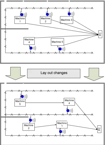
(27) Chapter 2 The principal projects in Wireless Sensor Network and their sponsor, and some figures are summarized in the Table 7.. Table 7 Projects in Wireless Sensor Network Project in WSN. Company or Institutions. SensIt. DARPA. http://www.darpa.mil/body/archives/sensit/index.htm ZigBee. BBN. http://www.zigbee.org/en/index.asp Smart Dust. UC Berkeley. www.berkeley.edu Sensor Web. JPL. http://sensorwebs.jpl.nasa.gov WINS. UCLA. www.ucla.edu Power aware microsensor. MIT. www.mit.edu neuRFon ™. Motorola. www.freescale.com. 2.10.2 Description The Wireless Sensor Network is a technology that is able to monitor physical variables in many scenarios from environment, industry, security and battlefield, for example: traffic, habitat security, factory. 15.
(28) Chapter 2 appliances, water distribution, etc. These devices have the ability to extract information process it and show it for control; WSN consist of small (tiny) nodes and these nodes have the capability of sensing, computing and transmitting by wireless. This technology put together the next disciplines: tracking and localization, sensor data fusion, distributed databases, communication protocols, power management, architecture and design methodologies. These devices have a sensing unit, processing unit, transceiver unit, other characteristics are the “self-configuration”, and the “self maintenance”. The general model is shown in the Figure 3. The major challenges in this field are fault tolerances, scalability, power consumption, cost, etc. Each node operates or works not only as a host but also as a router, sending or forwarding packages to other nodes, a mesh network will be able to self-organize and self-configure to automatically establish and maintain the connectivity among themselves (ad hoc network). .(Havinga, Hou, & Feng Zhao, 2004)(Zorzi, 2004). Figure 3 General concept of Wireless Sensor Network The generic model for WSN is based in gathering and communication capabilities, but a specific model is based on the next assumptions: •. All Sensors have identical capabilities.. •. All sensors are anonymous.. •. The sensors can create a region.. •. Each sensor belongs to one region.. •. Each region has an address.. •. The communication between regions is based on address.. •. The sensor has synchronization property.. (Gracanin, Eltoweissy, Olariu, & Wadaa, 2004) According to (Zhao & Guibas, 2004) in their interdisciplinary research, the key definitions are: •. Sensor: A transducer that converts a physical phenomenon (heat, light, sound, motion, etc.) in electrical or other signals that may be further manipulated by other devices.. •. Sensor node: Device with sensor, processor, memory, radio transmission and power supply.. 16.
(29) Chapter 2 •. Network topology: A connectivity graph where each node is the sensor nodes and edges are the communication links.. •. Routing: The process of determining network path from a packet of the source node to the desire destination.. •. Embedded operating system (OS): The real time operating system supporting sensor network applications.. FAULT TOLERANCE There are a lot of network topologies but in WSN the star topology and the distributed topology are the main. The star topology is more vulnerable to a failure central node. The distributed network topology provides multiple paths for the communication; redundancy level is used to describe the number of links in the networks topology. The WSN needs a high degree of fault tolerance because the lost links caused by the node distribution, mobility and the stochastic behavior of the wireless of medium. (Bilstrup, Sjoberg, Svensson, & Wiberg, 2003). 2.10.3 Applications of Wireless Sensor According with (Callaway, 2003) the application of WSN is possible in these areas: •. Industrial Control and Monitoring:. •. Security and Military Sensing. •. Asset tracking and Supply Chain Management. •. Agriculture and Environment. •. Health Monitoring. •. This research focus in the industrial control and monitoring. •. Industrial Control and Monitoring:. In those fields the WSN can be used for monitoring temperature, pressure, humidly, etc, in the floor factory and these devices also can monitor toxic or poison substances. The modern systems in the industry are becoming more and more complex; this increase of complexity increase the value of the systems or machinery, therefore, the desire for automated prognostic and held monitoring systems are growing constantly. The sensors can monitor the critical variable (such as temperature, humidly, vibration, pressure, etc) and with this information held monitoring or automated prognostic can optimize in time and costs, but these sensor must be wired, therefore, the wiring the sensor increase the systems cost and the weigh in equipment or machinery. Wireless Sensor Network can be considered as such option for decrease time, cost and weigh in those systems. (Haowei Bai, Atiquzzaman, & Lilja, 2004) Another application may be monitoring the environmental temperature and humidity in buildings or offices to substitute the wired thermostats used in HVAC. A typical WSN has hundred or thousand of sensor network, they have the ability to communicate either among each other or with the external base station. Each sensor is able to collect and route data to near neighborhood sensor or to base station and the base station is able to connect with external protocols as. 17.
Figure
+7


Documento similar
Finally, specifications are independent of the implementation language, and they can be used for testing implementations written in different languages. In particular, the approach
Finally, the main objective of the work is to develop a complete study of the manifold multiplexer, its circuit model optimization and a complete design (from the ideal circuit model
de Inform ´atica e Ingenier´ıa de Sistemas, University of Zaragoza,
Government policy varies between nations and this guidance sets out the need for balanced decision-making about ways of working, and the ongoing safety considerations
In this thesis, we present a neural network architecture based on Mixture Density Networks to explicitly learn the channel model for end-to-end communications for SISO and
The empirical study carried out using quantile regression confirms that visitors to theme parks who are willing to pay a high price for express passes are
The aim of this research was to develop a numerical model which explained the radial flow phenomena from the fluid mechanics point of view in the developed non-contact end
sized enterprises (M‐SME). In this proposal, we imply that facilitating their development is a natural way to improve their performance,
