INDEX
1. INTRODUCTION
1
2. THEORETICAL CONCEPTS OF AERODYNAMICS
2
3. NACA 4 DIGIT SERIES FOR WING CROSS SECTIONS 4
4. MAIN FORCES ACTING ON AIRCRAFT
4
5. BASIC CALCULATIONS
5
6. DESCRIPTION OF THE UAV
8
7. INTERNAL COMPONENTS
9
7.1 Engine 9
7.2 Propeller blade 10
7.3 Batteries 12
7.4 Servomotor 12
7.5 Speed controller 13
7.6 Autopilot 14
7.7 Telemetry 14
7.8 GPS 14
7.9 Altimeter and Bluetooth adaptor 15
7.10 Pitot tube and sensor 15
8. CONSTRUCTION
15
8.1 Fuselage 15
8.2 Wings 18
8.4 Horizontal stabilizers 22
8.5 Horizontal flap 22
8.6 Vertical flap 23
8.7 Support 23
8.8 Batteries 24
Flight endurance 24
8.9 Plate support of the electronics 25
8.10 Motor 25
8.11 Propeller 26
9. DRAWINGS
29
10. MATERIALS
31
10.1 Glass fibre 31
10.2 Airex ® 31
10.3 Aluminium 32
10.4 Carbon fibre 32
10.5 Composite 33
10.5 Balsa Wood 33
11. MANUFACTURING PROCESS
34
12. CONTROL SCHEME
37
13. ANALYSIS
38
13.1 Calculation of the speed and the lift coefficient in an horizontal, straight and uniform flight 38
13.2 Static analysis of the drone 41
13.3 Stress analysis in an accident against the floor 43
Fuselage 44
Wings 46
Aluminium support 47
Composite (balsa wood, carbon fibre, Kevlar) 50
14. ECONOMIC CALCULATIONS
53
14.1 Human resources budget 53
14.2 Hardware budget 53
14.3 Software budget 55
14.3 Total budget 55
15. ENVIRONMENTAL REQUIREMENTS AND SAFETY
USE
55
16. CONCLUSIONS
56
17. BIBLIOGRAPHY
57
1
1. Introduction
In the last years, the development of unmanned aerial vehicles (UAV) has had a very significant progress, moreover for the use in civilian applications. The most usual applications of this kind of vehicle are focused in tasks where the access is difficult or dangerous, like, for example, surveillance and following tasks, geographical recognition, etc.
Within the field of UAV, there is a lot of investigation focused in small UAV, called Mini-UAV, which are the topic of this project. The development of these systems has been possible thanks to the great progress of microcontrollers, which offer the possibility of making really complex calculations in a very small place, the miniaturization of the sensors (MEMS: Micro ElectroMechanical Systems) as well as the improvements in the energy storage systems.
This project is about manufacturing a UAV driven from land. The idea of the project is to create from zero a design that can be used and improved in the future.
To decide the final shape of the UAV, it has been taken in account different designs that actually exist and are used for totally different purposes.
As an example of these models, it is the case of the UAV Zephyr (Figure 1), a HAPS (High Altitude Pseudo-Satellite) UAV designed by Airbus. The wings of this aircraft are not totally straight, giving it higher stability while flying.
Figure 1: UAV Zephyr 8. [1]
2
Figure 1.2: UAVMQ-1 Predator. [2]
The last example is a RC model for personal use, the AeroSky RC RoboSurfer UAV Glider Plane, with an electric engine to make it fly. The shapes are simpler in this case.
Figure 1.3: Toy UAV. [3]
The final shape of this UAV mixes different elements of these cases, trying to be attractive for the consumers while is still fulfilling the rest of its objectives (endurance of flight, mechanical properties, etc.).
2. Theoretical concepts of aerodynamics
Aerodynamics studies the solids behaviour when there is a relative movement between them and a fluid in contact with them, being the air in this particular case.
Is necessary to know the aerodynamic concepts that rule the behaviour of the vehicle that is going to be tested, because in other case it should be necessary make real tests.
3 There are a lot of different configurations and sizes for the wings, where their design depends on the application of the UAV. In case of a low speed aircraft, the rectangular wings are better. If it is wanted higher speed, the triangular shape is more adequate. But independently of this, the most important factor in the wing’s design to consider is the wing area, because it will define the sustentation.
In aeronautic is called wing to an aerodynamic body that is composed by aerodynamic sections and is capable of generate a pressure gradient when it moves within the air. As a consequence of this gradient, it takes place the stall that allows the UAV to fly.
Aerodynamic profile
An aerodynamic profile (Figure 2.1) is a planar surface that, when it moves along its way through the air creates a pressure gradient that generates a reference stall. The parameters that have influence in an aerodynamic profile are:
1. Chord line: Is the straight line that goes from the leading edge to the trailing edge. The chord length, or simply chord, is the length of the chord line. That is the reference dimension of the airfoil section.
2. Camber line: Is the locus of point’s midway between the upper and lower surfaces. Its shape depends on the thickness distribution along the chord.
3. Thickness: It varies along the chord. It may be measured in either of two ways:
Thickness measured perpendicular to the camber line. This is sometimes described as the "American convention".
Thickness measured perpendicular to the chord line. This is sometimes described as the "British convention".
4. The suction surface (upper surface): It is generally associated with higher velocity and lower static pressure.
5. The pressure surface (lower surface): It has a comparatively higher static pressure than the suction surface. The pressure gradient between these two surfaces contributes to the lift force generated for a given airfoil.
4
The leading edge is the point at the front of the airfoil that has maximum curvature (minimum radius).
The trailing edge is defined similarly as the point of maximum curvature at the rear of the airfoil.
Finally, important concepts used to describe the airfoil's behaviour when moving through a fluid are:
1. The aerodynamic centre: Is the chord-wise length about which the pitching moment is independent of the lift coefficient and the angle of attack.
2. The centre of pressure: Is the chord-wise location about which the pitching moment is zero.
The profiles can be symmetric or not:
Symmetric profile: The advantages are that this kind of profile is easier to build. Non-symmetric profile: This profile gives higher level of sustentation to the aircraft.
3. NACA 4 digit series for wing cross sections
The NACA (National Advisory Committee for Aeronautics) was a federal agency from USA founded in 1915 with the mission of promoting and undertaking the aeronautics investigations.
The NACA developed the 4 digits series, which is the first family of sustentation surfaces.
First digit means the maximum inclination of the chord (expressed in percentage). The second digit is the position of the maximum curvature expressed in chord decimals. And the last two numbers are the thickness of the surface in percentage.
4. Main forces acting on aircraft
The four main forces acting on aircraft are showed in Figure 4.1.
4.1 Lift force
Is an aerodynamic force generated by an object that moves along the fluid. Is the foce that keep the aircraft in the air. Is generated by all the body of the aircraft, but most of it is generated by the wings. It is perpendicular to the movement direction. Its magnitude depends on some factors as the shape, the size and the speed.
5 Is the force caused by the gravity acting on the mass of the aircraft. Its application point is the centre of mass.
4.3 Drag
Is the force that is created by the air resistance to the displacement of the aircraft. This force opposes the movement of the drone.
4.4 Thrust
Is the mechanic force that generates the engine and the propeller to move the plane through the air. Its direction depends on the position of the engines and its magnitude depends on the power of them.
The direction of the plane when it is flying depends on these forces. If these four forces are balanced, the UAV will fly with constant speed. To accomplish this is necessary:
Lift = Weight Drag = Thrust
Figure 4.1: Forces acting on an aircraft. [5]
5. Basic calculations
6
easily. This is the first calculation that has to be done to know if the UAV will take off from land.
First of all, is necessary to use the equations of the lift and drag coefficients:
(5.1)
(5.2)
where CL and CD are the lift and drag coefficients, respectively, FL and FD the lift and drag
forces, ρ is the air density, v the velocity of the UAV and A is the wing area.
To calculate lift coefficient it has to be known the Reynolds number in the conditions of the flight. The Reynolds number can be calculated with the following equation:
(5.3)
where ρ is the air density, v the UAV speed, l the chord length, µ and
are the dynamic and
kinematic viscosities of the air.For the design, it has been decided that the chord of the wing will be 500 mm in its maximum, 350 mm in the medium section and 200 mm in the wing extreme. The drone has been designed to have 4.2 m of wing spare, which means that the wing area is 1.47 m2. These measurements are usual in drones of this kind, to be used in open areas with medium speed.
The attack angle of the wing (α) it has been set in 0º and the maximum speed 17 m/s.
With all this data, is possible to start the calculations to estimate the maximum weight of the drone.
For the wing section it has been chosen the MH 32-il section, which will provide the UAV more sustentation than a symmetric cross section. This section is usual in aircrafts with the same purpose.
According to the selected characteristics, the Reynolds number can be calculated by using equation 5.3:
5.4
7
Figure 5.1: Graphic of the CL/α curve for MH 32-il profile. [6]
As what is wanted is the attack angle to be 0º, it has to be checked where the vertical line on 0º cuts the two lines. As it is seen in the graphic, both lines match when they cut the 0º line for attack angle, so no interpolation between them is needed.
The value for CL, looking at this graphic is 0.3. Taking the 5.1 equation is obtained how much weight the UAV can weigh.
(5.5)
To get the maximum mass that the wing area selected can carry it is only needed to divide the weight force calculated in 5.5 by the gravity acceleration:
(5.6)
8
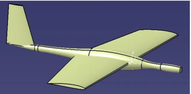
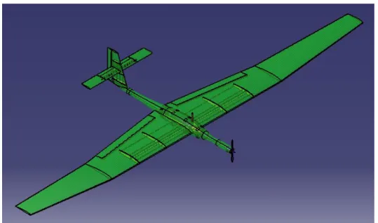
6. Description of the UAV
The UAV has a shape similar to the one showed in the first point called Zephyr (Figure 6.1). The idea is make it in one entire piece to simplify the process of manufacturing and the costs.
Figure 6.1: General view of the UAV.
The wings have a special shape, which will be described deeply in the following points. They change their section length from 500mm of chord in the beginning, where the wings connect with the fuselage, to the final 200mm of chord length in the end. At one point, the wings have an angle different from zero with the horizon, gaining, the aircraft, in stability.
This drone does not have wheels for land or take off, so the way of taking off can be by just grabbing with the hand and turning on the engine, or it can be with the help of a platform that throws the drone to the air (Figure 6.2). In this case, is good to know that, for this cross section, the maximum CL/CD coefficient possible to obtain is obtained with a 4.75º of angle of attack. So this would be the best inclination of the launcher platform.
9 It only has one propeller connected to two engines working as one. These engines are fed by 4 batteries, which provide the drone of enough power to keep flying during 16 min until is necessary to charge them.
Inside the UAV there is an Aluminium square tube which encloses the electronic components that are necessary to have control of the drone: autopilot, GPS, altimeter, Pitot tube, batteries and the radio control receiver.
In the head of the UAV are founded the servomotor and the motor. That is the reason why the head is a little bit wider than the neck.
7. Internal components
In this section are shown the internal components that will be inside the UAV.
The fuselage is prepared in the front to ensure the engines by putting them on the frontal structure.
For the rest of components it has been placed a metallic profile inside the body of the UAV that will be secured fuselage, which has the shape in its body to embrace the profile. The batteries and all the rest of the electronic components (GPS, radio controller, etc.) will be attached to the profile, which can be taken when the UAV is dismounted to change them or charge the batteries.
The specifications showed in this part are just the ones that are necessary to design them in CATIA as realistic as is possible. The rest of the specifications can be seen in the References part, where all the items are listed with the website where they can be found.
7.1 Engine
It has been used a brushless motor, because this kind of motors have a higher efficiency than the brushed ones, as the lack of brushes means less engine wear.
The engine selected is a powerful motor that will allow to fly a heavy drone. The reason of choosing this engine is because in the design is wanted just one motor, so the thrust have to be as much as possible.
The product chosen is the brushless outrunner motor called ‘Emax BL2832/05’
The specifications of it are the following:
Dimension: 39 mm or diameter x 53.5 mm of length Weight: 210g
Diameter of axis: 5 mm RPM: 960 rpm/V Voltage: 6-17 V
Maximum current: 69 A
10
Recommended aircraft weight: 2000-4600 g
This engine has enough thrust to carry on with a UAV that weighs 4600g as maximum. This means that the past restriction of weight, given by the wing surface, it is not enough.
The drone has to weigh 4600g as maximum.
Figure 7.1: Emax BL2832/05 brushless motor drawing. [8]
7.2 Propeller blade
The motor selected recommends specifics propeller blade measurements. It is recommended a 14inch blade.
To confirm the thrust that the selected motor can give with a propeller with this characteristics, it has been used a program called ‘Drive Calculator’
In this application it is possible to calculate the thrust that the engine will give with an specific propeller by introducing the RPM, the voltage and the current.
The motor has a 960rpm/v rate, and it will be fed by batteries with 11.1v. The current introduced is the maximum efficiency current for the motor. The propeller chosen is the one that is recommended by the motor manufacturer, a propeller with 14inch length and 7inch of pitch.
RPM = 960rpm/v · 11.1v = 10656rpm
11
Figure 7.2: Thrust calculation with Drive Calculator. [9]
The thrust calculated for this configuration engine-propeller is 5935g, a 30% more than the maximum weight allowed.
The usual recommendation is that the weight of the plane must not be more than the 90% of the thrust. So, in this case, the UAV is in the safety side of this rule.
Between the blades that meet the requirements, it has been chosen the propeller ‘Aerostar
Composite Propeller’, which has different hub inserts to suit with different motor shafts, so it will fit with the engine selected.
Specifications:
Length: 14 inch Pitch: 7 inch
12
7.3 Batteries
When choosing a battery, there are three characteristics to consider:
Constant current Capacity
Voltage
It has been selected a LiPo battery, because this kind of batteries are capable of give a high quantity of energy in a short time, and they are very light.
The product selected for this mission is ‘Turnigy Graphene 6000mAh 3S 65C Lipo Pack’, a Graphene Li-Poly battery with three cells.
Specifications:
Capacity: 6000 mAh Number of cells: 3 Voltage: 11.1V
Discharge: 65C constant /130C burst Maximum charge rate: 10C
Weight: 587g
Dimensions: 168x69x26 mm
Figure 7.4: Battery Turnigy nano-tech A-SPEC G2. [11]
7.4 Servomotor
13 It has been selected the analogic servo ‘RCTECNIC S3006’, which provides a 6kg torque at 4.8 volts.
Specifications:
Weight: 40 g
Dimensions: 40.8x20.1x38 mm
Figure 7.5: RCtecnic S3006 servomotor. [12]
7.5 Speed controller
The speed controller is a circuit that has the mission of generate a triphasic signal that feeds the motor.
The speed controller selected is ‘Brushless e-max Simon Series 80A – UBEC’. The GPS selected is ‘Quanum GPS Logger V2 with Backlit LCD Display NEO-6 U-Blox’
Specifications:
Constant current (max): 80A (100A) Dimensions: 86x38x12 mm
Cells: 2-6S LiPo Weight: 81g
The ESC selected works at a higher current than the engine. It has been selected that way, oversizing respect the engine, with the purpose of protecting it.
This ESC has, in addition, three kinds of protections:
Low tension protection: In case of turning off the engine immediately or reducing the power when the tension is lower than the protection threshold programmed, the engine stops working.
14
Overheating protection: When the temperature is higher than 110 Celsius degrees, the power is reduced at 35%.
7.6 Autopilot
The main part to control the drone while it is flying is the autopilot. Its function is to maintain the parameters of the flight under control to permit the drone fly without problems.
The autopilot selected is ‘Px4Pilot 32Bit AutoPilot Flight Controller’. It has included the gyroscope and accelerometer sensors.
Specifications:
Weight: 38g *
Dimensions: 81.5x50x15.5 mm*
*In this case, in the website shop is impossible to find these parameters, so it has been taken parameters from another model (the next generation) from another website.
7.7 Telemetry
Necessary to be informed about everything that happens in the UAV in real time. The telemetry permits the ground control to know the status of every sensor in the drone.
The product selected is ‘Quanum 2.4GHz Telemetry System (Volt/Amp/Temp/mAh) V3.1’.
Specifications:
Weight: 16g *
Dimensions: 50x17.5x2 mm*
*These parameters are only for the part that is going to be inside the aircraft.
7.8 GPS
The GPS provides information about the position of the drone with high accuracy in real time.
The GPS selected is ‘Quanum GPS Logger V2 with Backlit LCD Display NEO-6 U-Blox’
Specifications:
Weight: 43
15
7.9 Altimeter and Bluetooth adaptor
The altimeter permits the owner to know the altitude of the aircraft. The altimeter that it has been selected does not give information in real time, so it has been bought too an adaptor to send the information to the mobile phone of the owner with and specific app.
These two products are. ‘HobbyKing® ™ Altimeter’ and ‘HobbyKing® ™ Altimeter Bluetooth
Adapter for Wireless Android App’.
Specifications:
Weight: 1.3g
Dimensions: 21x13x5 mm Weight: 3.3g
Dimensions: 28x16x5 mm
7.10 Pitot tube and sensor
To know the speed of the UAV is necessary the Pitot tube.
For this it has been chosen ‘HK Pilot Analog Air Speed Sensor And Pitot Tube’.
Specifications:
Weight: 4g (sensor)
8. Construction
This UAV has been designed from zero to the final result. It has been taken into account the materials that can be selected and the different ways of manufacturing, that may affect the final cost of the UAV.
In this section it is going to be explained how it has been designed step by step. For this purpose it has been used the 3D computer-aided three dimensional interactive application named CATIA, which is used in a lot of different factories for design and engineering.
To make it easy to see, the UAV has different colours. The fuselage, wings and stabilizers are coloured in light green, and they are transparent to see the parts inside. The stiffener of the wings and stabilizers are light brown, the electronic components are orange above a black plate and the batteries and the components of the motor are purple.
8.1 Fuselage
16
batteries. It has been chosen this distribution because the centre of mass has to be in ¼ of the chord of the wing from when it begins.
The shape is as smooth as possible to avoid turbulences, and it continues until the stabilizer in the end.
The fuselage is, from the head to the end, one piece of the same material. This means that it will be easier to build the drone because the fuselage will be only two pieces to join. And another advantage is that it will be cheaper, because it will be necessary only the two moulds for the two parts of the fuselage, and the resin to join them.
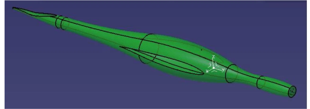
Figure 8.1: Sketch of the fuselage.
In the upper image it is shown the sketch of the fuselage. Once it is defined, it has been made a revolution of it and it has been obtained the primary surface that it is shown in the following picture.
17 Then the surface of the wings has been created and it has been cropped from the primary surface. The same process has been followed for the stabilizer. It is important to remark that the fuselage, in its end its curve, to make the moulds possible to manufacture.
Figure 14: Detail of the surfaces that were removed from the fuselage.
To end with this piece, it has been necessary make different holes in it. In the front face it has five holes. Four of them are in a circle of 25mm of radius. These holes are for the bolts that will ensure the motor inside. The central hole, with 5mm of diameter is where its axis will be placed. In the upper part it has one more hole where the Pitot tube will be placed.
18
Figure 17: Final result for the fuselage.
8.2 Wings
For the wings, it has been decided to use the MH 32-il profile (Figure 18) with a null angle of attack. This cross section will give a high level of lifting force because it is and asymmetric profile.
Figure 18: MH 32-il wing profile. [13]
The wings vary their chord length along they reach their limits. So, from an aerial point of view, the wings are narrower in their extremes than in their beginning at the fuselage. Moreover, at the half of the way from the fuselage, the wings change their angle with the horizontal and it becomes a 7º angle. This will give more stability to the UAV. This shape of the wings is typical in this kind of aerial vehicles.
To make possible to work with the most accurate shape of the cross sections, it has been used an Microsoft Excel macro that is given with the rest of the files in the CD.
This macro allows the user to introduce an unlimited quantity of points, by using its 3 dimensions coordinates, and introduce them in CATIA. It is possible to draw in CATIA the points, the spline that they define and a surface, in case that the spline can define it. For this work it has been selected the points and the splines, so the wings and stabilizers has been drawn with high accuracy.
To obtain the coordinates of the points that are part of the profile it has been used the data base found in the website ‘airfoiltools.com’. In this website it is possible to choose between lots of different wing sections and plot them using the lengths that are wanted. In our case it has been selected the MH32 profile and it has been plotted with three different chord lengths.
19 seven degrees, the chord length is 300, and in the extreme of the wing the chord length is 200mm. In the website it is possible to download one file with the X and Y coordinates of the sections, and after that the Z coordinate choose from the design.
In CATIA, once the three profiles are drawn in the programme, it has been created the surface of the wing by limiting it with the straight lines that can be seen in the image.
After creating this surface, the wing is fulfilled with material, and the flap is cut from the wing.
Finally, it is only necessary to shell the final shape, and make two holes that will allow the flap to rotate.
Figures19 and 20 : Initial curves and the surfaces made with ‘Multisection’ command.
20
Figures 24 and 25: Final results for right and left wing.
8.3 Vertical stabilizer
To make the vertical stabilizer it has been followed the same path that it has been used to get the wing profile, but in this case selecting NACA 63012A profile (Figure 26).
Figure 26: NACA 63012A stabilizer profile. [14]
Doing the same as it has been done with the wings, once the splines and points are in CATIA, the surface of the stabilizer has been made extending one section to the limit section following the two straight lines that are the limits. After that the surface is fulfilled with material.
When the filled is done, the vertical flap is cut from the stabilizer, and a hole is made to make possible for the flap to be placed.
21
Figures 27 and 28: Initial curves and surfaces made by ‘Multisection’ and the final surface with the cone below.
Figure 29: Detail of the body to remove from stabilizer.
22
8.4 Horizontal stabilizers
For the horizontal stabilizers it has been used the same cross section as the one used for the vertical stabilizer. Here is not necessary to use an asymmetric profile because these stabilizers will not generate lifting force. Their mission is to keep the UAV flying stable.
For these parts it has been only made and Extrude operation of the wing profile and then used Thickness to give them the necessary thick.
Figure 31: Initial curve and final result for the horizontal stabilizers.
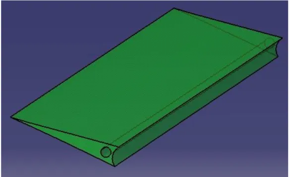
8.5 Horizontal flap
This piece it has been made from the wing. Following the same process that has been made to create the wing, once it is filled, the flap is cut, and the part that is wanted to remain is the opposite that remained before. After that, the flap is limited and cut by two planes.
Finally, a hole during the whole flap is made to place it in the wing.
23
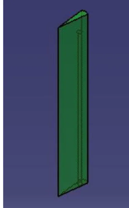
8.6 Vertical flap
The same process is followed to make this flap. With the stabilizer filled, the flap is cut.
After that, a cylinder is created to place the flap in the stabilizer.
Figure 31: Initial curve and final result for the horizontal stabilizers.
8.7 Support
24
Figure 37: Metallic profile for protecting electronic components.
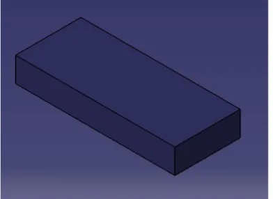
8.8 Batteries
The electronic components have been designed in CATIA with the information obtained in the websites where these components are going to be bought.
All of them have been simplified by the three lengths that are showed in the websites, and then their weights have been assigned too to make possible to calculate the total weight.
Figure 38: Simplification of the batteries.
Flight endurance
The UAV has 3 batteries of 6000mAh, so the total available is 18000mAh with a nominal voltage of 11.1V.
To make the calculations is only taken into account the engine consumption, because the rest of the consumption, caused by the electronic components is very small.
Consumption of the engine at its maximum power:
25 Time of flight at max power:
(8.2)
So the flight endurance is 15 min 39 s until the batteries discharge completely.
This is the time flying at max power, but the UAV will not be working always at max conditions, so the autonomy is a little bit higher.
8.9 Plate support of the electronics
The batteries will be placed directly in the support, but all the electronic components will be glued and placed over a plastic plate that will be their support. This plate will be placed in the support.
Figure 39: Simplification of the electronic sistems (GPS, RC, etc.).
8.10 Motor
The part of the engine is just a simplification of the real shape of the engine that it has been selected. It has been drawn the shape in one sketch and just extruded until the length that appears in the specifications in the website.
Once it is obtained, the axis that leads to the propeller is extruded.
26
Figure 40: Simplification of the engines.
The servomotor is drawn by the same process; it will be placed between the motor and the frontal face of the UAV.
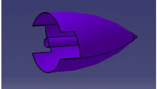
8.11 Propeller
The propeller is divided in two separated parts.
The first one is the ‘peak’ of the UAV. It is just a revolution of half of the cross section, and after that is made a pocket operation to recreate the real shape where the propeller has to be located. This shape has been taken from the real one that is going to be used in the UAV. It is just an approximation.
The second part is the propeller, properly said. It has two blades and, as the other part, is just and approximation, as realistic as possible, of the real propeller that will be used.
27
Figure 41 : View of the propeller from behind.
Figure 42: Right view of the propeller blade.
29
31
10. Materials
Here are described all the materials used for the different parts of the UAV.
10.1 Glass fibre
The fuselage, the wings and the stabilizers are made of glass fibre (Figure 10.1). The thickness of these parts is 0.32 mm. All of them are supposed to be made by moulding, typical in this kind of situations
The glass fibre selected is a kind of glass fibre specific for aeroplane modelling, with 80g/m2 of surface density and 0.08 mm of thickness. So the drone will have four layers of this material to reach the 0.32 mm of thickness in its parts.
Moreover its low weigh, it has high resistance. It can reach a 1080 MPa in the longitudinal way, but 50 MPa in the transversal one. Other advantage is that it is cheaper than the carbon fibre.
Figure 10.1: Example of a glass fibre wing. [15]
10.2 Airex ®
This material is the filler of the UAV (Figure 10.2). It will be applied over the glass fibre layers, following the same process. This material acts as insulation and it has very good behaviour in fire. It will protect the components inside the aircraft from the extreme temperatures and the external elements that may be able to filter through the chassis.
32
Figure 10.2: Example of the appearance of the filler [16]
10.3 Aluminium
The plane rods that embrace all the electronic components are made of aluminium. They can be bought with the specified width in the website.
It has been chosen aluminium because of its really good resistance/weight relation.
It has a very low density (2.7 g/cm3) and a very high resistance; depending on the alloy selected it can reach 690 MPa.
Moreover, is a very cheap material and easy to mechanize.
10.4 Carbon fibre
The first option for the stiffeners is the carbon fibre. It is a very efficient material, with high mechanical properties but being very light.
Its resistance is similar to the glass fibre, being 1100 MPa in the longitudinal direction and 50 MPa in the transversal one. The disadvantage against the glass fibre is its elevated cost.
Another advantage is that it is resistant to the heat and the ambient conditions.
33
10.5 Composite
The second option for the stiffeners is this composite. This composite is formed by transversal small layers of balsa wood with two layers of carbon fibre over it, creating a sandwich. The first idea was to do use this composite in bars surrounded by Kevlar thread, which gives it more strength, but is enough and cheaper to use just the composite formed by carbon fibre, balsa wood, and the epoxy resin necessary to join them.
Figure 10.4: Explanation of how the composite is fabric. [18]
10.5 Balsa Wood
For the stiffeners of the wings it is going to be used balsa wood, a material with a very low density (100 kg/m3 – 150 kg/m3) and resistance. But with the way it is going to be used, mounting a structure inside the wing to make it more rigid, is only necessary its low weight.
34
11. Manufacturing process
The process of fabrication consists in the moulding of advanced composites in moulds, which will be later joined with epoxy resin.
As it is shown in the drawings, the external parts of the UAV are divided in two parts. This is because the process of moulding. For this UAV it is necessary to make 10 moulds, two for each piece, but with the two horizontal stabilizers using the same two.
The fact that the UAV is made of glass fibre makes this part more expensive than if the drone was made of aluminium, but the restriction of weight forces to use this material and its moulds.
Figure 11.1: Two moulds for the same part of one aircraft, the fuselage. [20]
Once the moulds are created, they are filled with glass fibre composite. This material is placed layer by layer manually in the moulds, giving one layer of epoxy resin between them, to join all the layers and make the wing resistant. The epoxy resin acts as glue between the layers and as reinforcement.
35 Figure 11.2: Placing the glass fibre into the mould. [21]
Figure 11.3: Putting epoxy resin to join the layers of glass fibre.[22]
In case of building a big dimensions aircraft, is very important the way of placing the composites because the direction of the fibres affects to the mechanical behaviour of the final product.
When filling the moulds, the two moulds of one piece of the drone (one wing, the fuselage, etc.) must be filled with the composites at the same time, to join them instantly after the resins are cured. Before the wings are joined, the balsa wood stiffeners must be placed inside them.
36
Figure 11.4: Moments before the union of the moulds with pressure and heating. [23]
The covers for of the UAV are built now. The next step is placing the engines and the electronic components inside before the two parts are joined.
The electronic parts that are going to control the drone have to be glued to the plastic plate. This plate and the group of batteries are going to be placed inside the support. Then, the batteries with their boxes have to be placed on the other side of the big tube. The Pitot tube has to be inserted in the hole of the tube, and glued to it.
Once all the electronics are ensured in the aluminium profile, it has to be placed inside the space made for it in the fuselage. It is not necessary to join the tube to the chassis.
The servomotor, the motor and the propeller have to be placed in the frontal part of the UAV, and after that they have to be connected to the control system.
After putting the electronics inside the fuselage, the two moulds of this part have to be joined.
When all the parts are built, the stiffener bar has to be placed in the rectangular hole of the balsa wood stiffener, and then, the wings can be settled and glued to the fuselage. The vertical stabilizer can be placed too in the back hole of the fuselage and glued too.
38
13. Analysis
The drone is designed and it is proved that it can fly without any problems.
In this point is going to be shown what would happen in case of losing control of the UAV and crashing against the floor while flying.
First of all it will be calculated the cruise speed of the drone. It will be shown the theoretical way and the calculation with a computer.
After that, it is going to be shown the static analysis of the drone, to show that it meets the parameter named before, the weight and the measurements.
Finally, it is going to be supposed a crash at this cruise speed with a determined angle and it will be shown the forces in some key parts to see if they can support these forces.
13.1 Calculation of the speed and the lift coefficient in an horizontal, straight and
uniform flight
First of all, it is started from the equations of motion:
(
)
(13.1)(
)
(13.2)These equations can be simplified for a cruising flight, which is a known situation of and horizontal, straight, symmetric and stationary flight, where the horizontal and vertical accelerations are zero. So, the equations 7.1 and 7.2 become:
(13.3)
(13.4)
The angle of attack, α, and the angle between the motor shaft and the wing chord line, αT, are usually very small. If the drone is in a cruising flight, which means flying at a constant height, which means that γ=0, so the equations are reduced to:
(13.5)
(13.6)
So, as in the preliminary explanation point was said, in a cruise flight, the stall is the same as the weight and the aerodynamic resistance is the same as the thrust of the UAV’s engine, where the stall and aerodynamic resistance are defined by the equations 5.1 and 5.2. These equations, written in another way and changing FL and FD by L and D, become:
39
(
)
(
)
(13.8)From the first equation can be obtained a way to substitute CL in the second one:
(13.9)
(
)
(13.10)
The equation 13.10 leads to a quartic equation to solve the speed that satisfies the condition of vertical symmetric flight:
(
)
(13.11)
Because the complexity of this process (are needed different parameters to solve it), it has been used a computer programme prepared to find flying characteristics of drones. This programme is called ‘MotoCalc’. It has a huge data base with different components of a UAV, like motors, propellers, batteries, etc. But, in this case, is possible to write the specifications of the components of the UAV directly in the programme.
It is needed too to introduce in the executable some characteristics of the UAV. These are its wingspan, weight without payload and the cross section used with all its characteristics (max. camber, angle of attack, etc.).
40
Figure 13.1: Interface of the program MotoCalc with all the information of the UAV. [24]
With all this information, MotoCalc do some calculations and shows the result for different velocities, and the one that generates enough lifting force is 9.5 m/s. The program gives too the stall speed, which is 6.5 m/s.
41 So, the flying speeds for this drone are:
Stall speed: 6.5 m/s Cruise speed: 9.4 m/s
The static pitch speed (17,1m/s) is within the range of approximately 2,5 to 3 times the model's stall speed (6,5m/s), which is considered ideal for good performance.
With a wing loading of 25,3g/dm², a model of this size will have very sedate flying characteristics. It will be suitable for relaxed flying, in calm or very light wind conditions.
The static thrust (1843g) to weight (3713g) ratio is 0,5:1, which will result in medium length take-off runs, and no difficulty taking off from grass surfaces (assuming sufficiently large wheels).
At the best lift-to-drag ratio airspeed, the excess-thrust (1228g) to weight (3713g) ratio is 0.33:1, which will give strong climbs and rapid acceleration. This model will most likely readily loop from level flight, and have sufficient in-flight thrust for many aerobatic manoeuvres.
13.2 Static analysis of the drone
The maximum mass that the drone can have was obtained from the motor specifications. In the next tables are shown the masses of the different parts of the drone, separated in 4 groups: the chassis of the UAV, the supports for the internal elements, the propulsion components and the control components.
The stiffener bar that joins the two wings appears separated to see the difference between the composite and carbon tube mass. This will be a start point in the decision of which one will be in the final design.
Chassis
Part Weight (kg) Qty.
Fuselage 0.161 1
Wing 0.555 2
Vertical stabilizer 0.045 1 Horizontal stabilizer 0.039 2
Wing stiffener 0.02 2
Vertical stab. stiffener 0.005 1 Horizontal stab. stiffener 0.002 2
Flap 0.043 2
Flap 0.01 1
42
Metalic supports
Part Weight (kg) Qty.
Support 0.263 1
Support 2 0.003 1
Support 3 0.039 1
TOTAL 0.305
Propulsion
Part Weight (kg) Qty.
Motor 0.21 1
Propeller 0.004 1
Battery 0.587 3
TOTAL 1.975
Stiffener between wings Weight (kg)
Composite 0.278
Carbon tube 0.013
The total weights for the UAV with these two configurations are:
With composite: 4.373 kg With carbon tube: 4.108 kg
So there is a difference between both weights of 6%, being both under the maximum weight limit imposed by the motor.
This means that the drone will not have any problems to fly with any of these materials. The weight is not a valid criterion of decision.
The drone’s weight has been calculated by CATIA too, which displays more information about the mass of the UAV. In Figure 13.2 it can be seen all this information. In this picture it can be seen the weight of the aircraft with the composite bar, with a difference of 2 mg from the weight calculated theoretically, because of the rounding.
In the picture, below the weight and volume of the drone are the inertia moments calculated by CATIA. All of these moments are really small, so the UAV are really good balanced.
Control
Part Weight
(kg) Qty.
Autopilot 0.038 1
GPS 0.033 1
Altimeter 0.003 1
Speed
controller 0.08 1
Servomotor 0.016 3
Battery 0.041 1
Pitot 0.01 1
Tx 0.016 1
Plastic support 0.007 1
43 Figure 13.1: Interface of the program MotoCalc with all the information of the UAV.
This information is referred to the centre of mass, which is shown in the following picture (Figure 13.2).
Figure 13.2: Interface of the program MotoCalc with all the information of the UAV.
The centre of mass is the intersection point between the three inertia axis of the UAV, coloured red, blue and yellow. It is in a good position, right in front of the sustentation centre, and between the limits of the positioning of centre of mass in an empty aircraft. This means that the UAV will be easy to pilot and its behaviour in the air will be good.
13.3 Stress analysis in an accident against the floor
44
UAV crashed flying at this speed. Different parts of the UAV that an important for protecting essential components will be tested to see if they can support the forces and accomplish the mission of keep safe the internal components of the drone.
It has been supposed that the crash would not be at a perpendicular direction to the ground, for obvious reasons. In a moment where the pilot can lose the control of the UAV it would crash with and angle smaller than 45º. It has been chosen a 35º angle in the crash.
Once the speed is decided, is needed the acceleration that the drone suffers in the accident. It is supposed that the time needed to decelerate the aircraft from the cruise speed to zero is 0.1s. The acceleration in this case would be:
(13.21)
This acceleration is in the direction of the crash. Dividing it between the two components, horizontal and vertical, the final acceleration is:
(13.21)
These values have been introduced in CATIA, in its module of Analysis, and the pieces that have been studied are:
Fuselage
Wings and stiffeners Electronic support
From the fuselage is wanted to maintain its shape. That would guarantee the safety of the components inside and it would avoid repairing it. The most important part is the frontal, because there is where the motor is, and is important that the motor does not suffer any damage.
The wings and their stiffeners have the same requirement.
In case that the other elements do not success, the support has to resist the forces because is basic that the electronic components survive to an accident.
Fuselage
45 the back the forces are caused by the stabilizers’ weight, in the middle are caused by the weight if the wings and the internal parts, and the frontal corresponds to the weight of the motor.
Figure 13.3: Results of the static calculations for the carbon tube case
The Von Mises diagram (Figure 13.4) shows that the most critical stress that the fuselage suffers is in the neck, where the section is smaller than in the frontal and the medium parts. The maximum tension that the neck reaches is 2.61·108 N/m2, which is ten times lower than the glass fibre Yield Modulus, so the fuselage will not break, but it will suffer deformations.
Figure 13.4: Results of the static calculations for the carbon tube case
46
Figure 13.5: Results of the static calculations for the carbon tube case
Wings
The Von Mises diagram for the wing shows that the wing does not suffer any stress in its entire surface but in just a point. The reason of this distribution of tensions is that the wing has a much sharped edge in the back. When the aircraft crashes, all the forces caused by the acceleration that the fuselage resist are transmitted by its surface to the wings. The surface that transmits these forces has 0.16 mm of thickness. This thickness and the edge of the wing together act as a tension concentrator.
But, even though all the stress is concentrated in one point, it is not enough. As is shown in the picture (Figure 13.6), the maximum value of the stress generated by the accident does not exceed the Yield Modulus of the glass fibre. So the wing will resist the impact.
Figure 13.6: Results of the static calculations for the carbon tube case
47 and the way it is placed in the fuselage. It works as a built-in beam bearing a uniformly distributed load, where the free extreme does not suffer torsion but it can move.
Figure 13.7: Results of the static calculations for the carbon tube case
Aluminium support
The next part that it has been studied is the structure made of aluminium rods welded that plays as a support for the electronic components. All of the systems are embraced by this support, so this is the reason why this is the most critical piece. It has to be able to confront the forces generated by the crash to keep all the electronic devices safe.
In this case, the support is resisting the weight of the internal components. The electronics’ weight is not important, but the batteries weigh enough to make this situation dangerous. In the Figure 13.8 it can be observed that in the back part of the support, where the batteries are placed, the horizontal aluminium rods, and in special, the one in the centre, are suffering a lot of stress. The welded areas are suffering much stress too.
48
Figure 13.8: Results of the static calculations for the carbon tube case
In the next picture (Figure 13.9) can be seen the deformation. The central rod will deform more than the other two, but they will deform too. The medium section of the central rod will displace 3.55 mm, while the medium sections of the extreme rods will deform 1.77 mm.
Figure 13.9: Results of the static calculations for the carbon tube case
Carbon fibre tube
For the rectangular stiffener that joins both wings it has been studied not only two materials, but two ways of positioning these materials. First of all it is going to be shown the study for the carbon fibre rectangular tube, with the narrow side facing down, and after with the wide side facing down. The same will take place for the composite made of carbon fibre, balsa wood and aramid.
49 rectangular stiffener. For the force of the accident transmitted it has been chosen only the two central surfaces of these six, because there will be the most important transmission of the force.
In Figure 13.10 it can be seen the stress distribution in the carbon tube, where the stress decreases from the two central application surfaces to the extremes, and increases from de middle to the upper and lower surface. This tension will not break the bar, but will make it deform a little bit.
In the figure 13.11 it can be observed that the deformation of the bar does not reach the 3 mm in the extremes, so it will be able to resist the impact. The rigidity of the carbon fibre tube will make that the wings will not deform as much as it was shown in the displacement diagram of the wing showed before (Figure 13.7).
Figure 13.10: Results of the static calculations for the carbon tube case
Figure 13.11: Results of the static calculations for the carbon tube case
50
Figure 13.12: Results of the static calculations for the carbon tube case
However, the displacement diagram (Figure 13.13) shows that the displacements are much higher than the other configuration with the narrow side facing down. Now, the maximum value of the displacement is 8.13 mm versus the previous 2.94mm, which means that the extremes of the tube suffer a 276% more displacement than before. This can create problems because the wings lie over this tube, so it is recommendable for it not to deform a lot to help the wings keep as rigid as it is possible.
Figure 13.13: Results of the static calculations for the carbon tube case
The conclusion of these graphics is that, in case of using the rectangular carbon fibre tube as the stiffener between the wings, the way of placing it that is going to be chosen is with the narrow side facing down, which is the most optimum way. The deformation is lower and the stress will be better resisted by the tube.
Composite (balsa wood, carbon fibre, Kevlar)
51 The module of the stress is not enough to make it break, so the stiffener will resist the impact.
Figure 13.14: Results of the static calculations for the carbon tube case
Due to the more rigidity of this composite, this stiffener will not have displacements as big as the carbon tube had. In Figure 13.15 it can be checked that the maximum displacement is 1.09 mm. The not symmetrical displacement distribution in the picture is because CATIA has problems when it is analysing assemblies of bodies where constraints have place. The calculation is accurate, but a little bit different where these constraints are placed.
Figure 13.15: Results of the static calculations for the carbon tube case
52
Figure 13.16: Results of the static calculations for the carbon tube case
In the displacement diagram (Figure 13.17) it can be seen that the displacements are much higher. The maximum is 4.38mm, four times higher than the displacement with the other configuration. So, in case of that the composite is used as the central stiffener, the configuration that has been used is with the narrow surface facing down, like with the carbon fibre tube.
Figure 13.17: Results of the static calculations for the carbon tube case
In conclusion, all the parts of the UAV will resist and impact against the ground, protecting all the components that are inside. Furthermore, they will not break, which would suppose a lot of money to get them made again. The only part that could have to be repaired is the aluminium support, a piece that is the cheapest and the easiest to make.
53
14. Economic calculations
To be able to see specifically the cost of all the parts of the project, it is going to be divided in three parts:
Human resources Hardware Software
14.1 Human resources budget
This project has been developed by one person. This person has had played the roles of project manager and mechanical engineering.
To complete the project will be needed an informatics engineer to set up the software that the drone will need to fly.
It has been estimated that the project would last 380 hours between all these roles.
In the following chart are showed by role, the cost that it represents.
Salary (€/h)* Estimated time (h)
Total (€)
Project manager 16.67 30 500.1
Mechanical engineer 16.45 300 4935
Informatics engineer 17.11 50 855.5
TOTAL 6290.6 €
Chart 10.1: Salary costs.
*Minimum salaries per profession in Spain. Source http://www.tusalario.es
14.2 Hardware budget
The hardware budget is referred to all the physical components of the UAV. They have been separated between electric and electronic components and structural components.
In the next table (Table 10.1) are showed all the prices of the components that will be mounted in the aircraft.
Components
Price (€) Price per UAV (€)
Engine 48.3 48.3
Propeller blade 3.4 3.4
Battery 69.73 119.46
Telemetry Tx 47.32 47.32
GPS 35.59 35.59
Altimeter 25.8 25.8
54
Pitot 21.43 21.43
Speed controller 46 46
Battery 6.6 v 2.75 2.75
Servo 7.5 22.5
Autopilot 53.4 53.4
TOTAL 413.52
Table 10.2: Prices of the components.
The quantity of material needed for the structural components of the UAV have been calculated by CATIA with its tool of measurement volumes and surfaces.
Fibre glass: 6.836 m2 Airex: 6.836 m2
Aluminium supports: 2900mm approximately
Carbon tube/ Composite: (20 x 10 mm) 1.5 m; (10 x 3.5 mm) 0.5 m Epoxy resin: 1.394 kg*
In the next table (Table 10.2) are showed the prices of the different materials needed in the construction of the UAV for both different cases, with composite stiffener or with carbon tube.
Materials
Price per unit (€) Price per UAV (€)
Glass fibre (m2) 7.5 51.27
Aluminium 6.75 13.5
Support
(2000mm) 11.6 6.37
Airex (m2) 23.09 157.84
Balsa wood (m2) 265 5.29
Epoxy resin (kg) 20.11 28.03
TOTAL 262.3
Chart 10.3: Information of the prices of the materials used.
Price per unit (€) Price per UAV (€)
Carbon fibre (m) 34.74 69.48
Composite (m) 26.05 52.1
Chart 10.4:
55 UAV with composite stiffener: 8.727.92 €
UAV with carbon tube stiffener: 8.745.3 €
The economic criterion shows again that the best option between the two stiffeners is the composite one.
14.3 Software budget
In the software budget is included the cost of the programmes that have been used to develop this project.
In the next chart are showed all the prices.
Price (€)
Microsoft Office 2010 69.99 CATIA (student license) 700
TOTAL 769.99
14.3 Total budget
Adding all the budgets is obtained the total cost that this project generates:
Price (€)
Human resources 6290.6
Hardware 8727.92
Software 769.99
TOTAL 15788.51
So the total cost of this project is: 15788.51 € which is a very low price for this kind of project.
15. Environmental requirements and safety use
The LiPo batteries that are used, if damaged or overheat, they can produce a fire. To avoid these problems they are in a protected part of the UAV and they are charged in an external and special charger for them.
The batteries may swell if they are not used as their instructions say. In example, if they are charged with a higher current that they allow, or if they are subjected to high temperatures during long time in use.
56
During the flight is convenient not to fly at the maximum power of the engine during a long time, because it can causes the overheating of the batteries or the rest of components.
The UAV has a tension measurer that says during the flight if the battery is not useful anymore, to have time to land and not put in any risk the UAV.
16. Conclusions
This project has a high technique difficulty. The principal objective was develop a multidisciplinary project where the design and the mechanical calculations where together. It has taken very long time to design every piece in CATIA, specially the wings, which cross section was necessary to be introduced in the program, but took weeks before finding the solution.
The value of what has been learnt in this project is incalculable, to have the experience to create a design from zero and let it ready to be made, always thinking in the best way to construct it from a quality/price point of view.
The drone crated here is apt to fly long distance with flight duration in the range of the drones that can be found in the market. This model, furthermore, is bigger, with big wings, so it can works as a glider with good results.
The next step is to test it in real flight, after configure its system to be able to fly, which is a task for an informatics engineer.
57
17. Bibliography
Moyano Díaz, Sergio. ‘Diseño y construcción de un quadcopter’.
Escamilla Nuñez, Rafael. ‘Diseño, Construcción, Instrumentación y Control de un Vehículo
Aéreo No Tripulado (UAV)’.2010
Barnes W., McComick. ‘Aerodynamics, Aeronautics and Flight Mechanic’ 2nd ed. Jonh Wiley and Sons Inc., 1995.
‘Problemas de aeronaves resueltos’. University of Sevilla.
‘Apuntes de aerodinámica’. University of Madrid.
18. References
[1] http://www.militaryaircraft-airbusds.com
[2] www.infodefensa.com
[3] http://www.nitroplanes.com
[4] https://en.wikipedia.org/wiki/Airfoil
[5]http://www.dutchops.com/Portfolio_Marcel/Articles/Aerodynamics/Forces/Forces/Acting_F orces.html
[6] http://airfoiltools.com/airfoil/details?airfoil=mh32-il
[7] http://www.uavfactory.com/product/21
[8] http://www.rctecnic.com/motores-brushless-para-aviones-rc/562-motor-brushless-outrunner-emax-bl2832-05-960kv
[9] http://www.drivecalc.de/
58
[11] http://www.hobbyking.com/hobbyking/store/uh_viewitem.asp?idproduct=91203
[12] http://www.rctecnic.com/todos-los-servos/2374-servo-analgico-rctecnic-s3006-6kg-estndar
[13] http://airfoiltools.com/airfoil/details?airfoil=mh32-il
[14] http://airfoiltools.com/airfoil/details?airfoil=n63012a-il
[15] http://www.goodaero.com/JSG/GOODAero.nsf/Products?Open
[16] http://www.airexbaltekbanova.com/airex-c70-pvc-foam.html
[17] http://173.199.132.77/browse/shaped-carbon-fiber-tubing/rectangular-carbon-fiber-tubing
[18] http://www.espritmodel.com/explanation-of-the-d-box-build-technology.aspx
[19] http://amaflightschool.org/getstarted/how-do-i-build-scratch
[20] http://www.sciencechannel.com/tv-shows/how-its-made/videos/how-its-made-gliders/
[21] http://www.sciencechannel.com/tv-shows/how-its-made/videos/how-its-made-gliders/
[22] http://www.sciencechannel.com/tv-shows/how-its-made/videos/how-its-made-gliders/
[23] http://www.sciencechannel.com/tv-shows/how-its-made/videos/how-its-made-gliders/
[24] http://www.motocalc.com/
[25] http://www.motocalc.com/
![Figure 5.1: Graphic of the C L /α curve for MH 32-il profile. [6]](https://thumb-us.123doks.com/thumbv2/123dok_es/6124227.178982/11.893.192.731.131.672/figure-graphic-c-l-α-curve-mh-profile.webp)
![Figure 7.2: Thrust calculation with Drive Calculator. [9]](https://thumb-us.123doks.com/thumbv2/123dok_es/6124227.178982/15.893.298.604.107.402/figure-thrust-calculation-drive-calculator.webp)
![Figure 7.4: Battery Turnigy nano-tech A-SPEC G2. [11]](https://thumb-us.123doks.com/thumbv2/123dok_es/6124227.178982/16.893.228.666.638.856/figure-battery-turnigy-nano-tech-a-spec-g.webp)