TIME REVERSAL TECHNIQUES IN NON DESTRUCTIVE TESTING
Mathias Fink; Claire Prada; Didier Cassereau; Estelle Kerbrat Laboratoire Ondes et Acoustique, ESPCI, UMR 7587 CNRS 10 rue Vauquelin
Paris, 75005 France
Tel 33 1 45870188 Fax 33 1 40794468 [email protected]
ABSTRACT
The objective of this paper is to show that time-reversal invariance can be exploited in acoustics to create a variety of new methods in non-destructive testing. Two different approaches will be discussed. The first one is the iterative time reversal process. It is an adaptive technique that can be used to detect flaws in complex samples with arrays of transducers. A second technique will also be presented: the D.O.R.T. method (French acronym for Decomposition of the Time Reversal Operator). It is a detection technique that is derived from the mathematical analysis of the iterative time reversal process and It allows the simultaneous detection and separation of several defects.
INTRODUCTION
There is always a need for new techniques for detecting and imaging small defects in solids. The detection of small defects with ultrasonic techniques is especially difficult when the inspected object is heterogeneous and has complex geometry. Diffraction theory tells us that large focusing apertures are needed in order to detect small defects with a good resolution, and several approaches have been extensively studied in order to achieve focusing in complex media. In many applications, the sample of interest is immersed in water and ultrasonic transducers are moved to scan the zone of interest.
In an initial approach, the beam focusing is achieved with one transducer whose geometry is matched to the liquid-solid interface and to the desired focal point [1]. In this technique, each transducer has a front face designed to equalize all the propagation times between the transducer surface and the desired focal point in the solid. This technique is problematic for thick samples for which many transducers of different geometries must be available to scan through the volume of interest. Step-by-step scanning of a sample using these transducers is increasingly time-consuming with improved focusing.
receive modes. Combination of transmit and receive focusing allows the achievement of high resolution.
However, all these techniques suffer important limitations. They are all based on an exact a priori knowledge of the geometry and acoustic properties of the sample and require highly precise positioning of the transducers. As the probe aperture becomes larger, the precision of the positioning needs to be higher which is not always available during NDE inspections. Another limitation of these techniques is that it assumes that ultrasound velocity is known and constant in each propagating medium. Because of these various limitations, self-focusing techniques have recently been proposed in order to improve the flexibility of the focusing process.
In a first attempt to solve these problems, adaptive focusing techniques have been implemented to correct phase distortions. After a first illumination of the region of interest, the echoes from the defect are received by the transducer array. In a technique proposed by Matthew O'Donnell for medical applications [3] and by Jan Achenbach for NDT [4], the received signals are cross-correlated and the time delays are determined by the time shift corresponding to the maximum of the cross-correlation between signals from neighboring transducer elements. This technique yields good results when the ultrasound field backscattered by the defect is dominant over the noise received by the array (electronic and acoustic). When several defects are located in the insonified region, the interference between the individual echoes gives a resulting backscattered signal with a poor spatial coherence, and the small degree of correlation between adjacent transducers limits the focusing process. Furthermore, in heterogeneous materials, the microstructure yields a strong scattering noise, which can hide the echo from the defect. This is the case for titanium alloys where a strong ultrasonic speckle is induced by the polycrystalline microstructure of the alloy. This is also the case for all grain material like steel and ceramics. Fibers in composite materials generate also a strong speckle noise. In nearly all these materials, the scatterers have a mean distance smaller than the ultrasonic wavelength (mm). In all these materials, looking at the received echoes makes target detection in presence of speckle noise difficult.
TIME REVERSAL METHODS
Another approach has been developed in our laboratory. It is based on the concept of time reversal (TR) invariance of the acoustic propagation and on the use of time-reversal mirrors. Time reversal invariance of the wave equations means that for every burst of sound diverging from a source- and possibly reflected, refracted or scattered by any propagation media - there exists in theory a wave that precisely retraces all of these complex paths and converges in synchrony at the original source, as if time was going backwards [5].
Time reversal mirrors
In an idealized time reversal experiment, an acoustic source (seismic source) located in a solid radiates a short elastic pulse (with longitudinal and transverse components of different velocities) that propagates through the solid and is transmitted in the surrounding fluid through the interface. Mode conversions yield a pressure field in the liquid that is measured on a closed surface surrounding the fluid. This surface is covered with reversible transducers (the time reversal cavity) that sense the field during a time T that is long enough for the wave to vanish. Once this field is memorized, the surface reemits the time-reversed signals. The time reversed field converges towards the initial source and mode conversions occur in the reverse way. Both the longitudinal and the transverse waves are recreated in the solid and they exactly converge in synchrony at the initial source location.
In practice, a time reversal cavity is difficult to realize. The time reversal operation is usually performed on a limited angular area called a time reversal mirror (TRM). Each transducer has its own electronics: detection amplifier, A/D converter, digital memory, and a programmable generator able to synthesize the temporally inverted signal stored in the memory
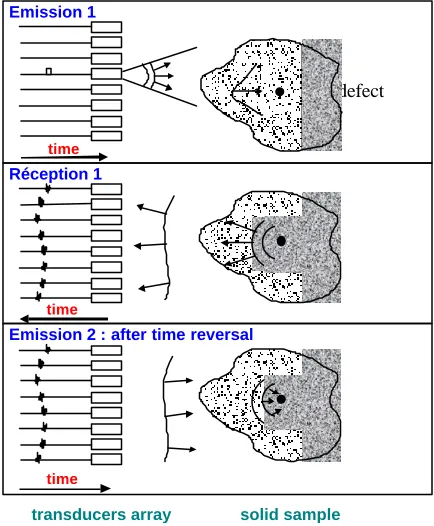
[image:3.596.189.406.243.506.2]In NDT, one has to work in pulse echo mode and the sources are not active like in the previous experiment but passive reflecting targets like defects. For this purpose, a TRM array may be used in the following multi-step sequence[6], see Figure 1. One part of the array generates a brief ultrasonic pulse to illuminate the region of interest in the solid. If the region contains a reflector, the reflected wavefront is converted by all the transducers of the array in electrical signals that are recorded. Then a time window is used to select the signals that are time-reversed and stored in electronic memories. The time-time-reversed signals are then transmitted to the transducers that transmit an ultrasonic wavefront that refocuses on the target through the interfaces. This process also compensates unknown deformation of the array and it can be iterated.
Figure 1
Another very attractive feature of time reversal processing is its speckle noise reduction capability. Indeed, if the speckle noise results from a random microstructure whose scale is less than the wavelength, the time reversal process cannot exactly refocus on the speckle noise sources. Each individual scatterer gives a time-reversed wave which focuses back on it with a diffraction spot, but the interference between all these spots yields a complex pattern that does not match the exact scatterer distribution. Using this property, we have developed processing techniques that allow to distinguish, during the inspection, a low-contrast flaw from high-level incoherent speckle noise.
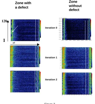
In a joint program with the French Society SNECMA (Société nationale d’étude et de construction de moteurs d’aviation), we have developed a 128 channels TRM to detect the presence of low-contrast defects within titanium alloys used in jet engines. Different 2-D arrays have been built in piezo-composite material, with a lateral dimension between 60 and 120 mm, a central frequency of 5 or 7.5 MHz. To find the defects, the TRM array and a titanium sample containing different defects are immersed in water facing each other. The titanium sample is first illuminated using the central part of the transducer array and the echoes are recorded by the whole array. In this experiment, the incident beam is only converted into a longitudinal wave propagating in the titanium (the speckle noise is weaker for longitudinal than for shear waves in titanium). In fig .2, the signals coming from a region containing a low-contrast defect are
Emission 1
defect
Emission 2 : after time reversal
transducers array solid sample
time
Réception 1
time
shown. Each horizontal line represents the acoustic echo amplitude received by one element as a function of time (or reflecting target depth). The vertical axis represents the code number of the array element. The echoes from the two titanium/water interfaces are clearly visible. Between these two echoes, we can observe the speckle noise caused by the titanium microstructure, but the echo from the defect is hidden by the high level of speckle noise. A portion of the acoustic signal is then selected using a short time window, time reversed, and reemitted from the whole array. The new recorded data (iteration 1) then shows a completely different behavior : a well contrasted wavefront appears in the window range. Although the defect is located 5 mm off- axis of the transducer array, the time reversal procedure has refocused the acoustic energy on it. The wavefront phase modulation corresponds to the wave backscattered by the defect that intercepts the 2D array with oblique incidence. A second iteration of the time reversal process gives a similar wavefront.
Figure 2
The same experiment, conducted in a zone without defect, gives a very different behavior : two different noise echo patterns, originating from the microstrucure, are observed after each illumination because the illuminated beams are different.
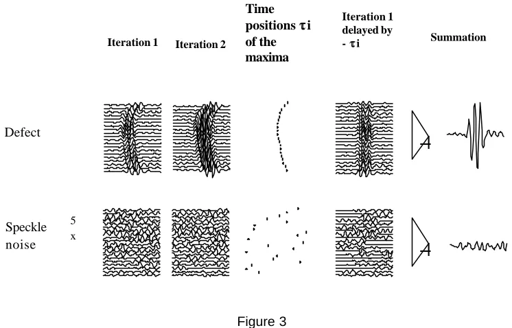
Although this technique gives spectacular results, it reduces only to self-focusing in transmit mode and a better signal-to-noise ratio may be obtained by focusing also in the receive mode. In the receive mode, we have to compensate the different time delays between the array elements and the defect before summation. But the estimation of the delays has to be done only if the window contains a defect. Indeed, we must be very careful when we estimate the delays in a window that only contains speckle noise. To be sure that the estimated delays cannot increase the speckle noise, we use a trick that consists in comparing two consecutive time reversal iterationsl operation Indeed, if the initial window selects the echo coming from a defect, the signals received after the second iteration contains the same wavefront, with the same
iteration 0
iteration 1
iteration 2
Zone with
a defect
Zone
without
defect
1
128
phase modulation (figure 3). This wavefront is an invariant of the time reversal process. We will see that it is, in fact, an eigenvector of the so called time reversal operator (next paragraph). If the window only selects speckle noise, the second iteration yields a different noise pattern. An automatic determination of the delay law is then made at the second iteration by measuring the arrival time of the peak signal on each channel. Once this delay law is determined, it is use to compensate the signals received at the first iteration. In case of a defect, the second iteration delay law is then optimal to compensate the signals from the first iteration and the summation of these signals give a high amplitude, but in case of speckle noise the second iteration delay law does not match the signals of the first iteration and the summation is ineffective. It is like one has introduced a random phase screen before the summation.
Figure 3
We have shown that the iterative pulse echo mode allows to autofocus and to detect defects as small as .4 mm in 250 mm diameter titanium billets. This technique offers better signal-to-noise ratio than alternative methods and it can detect smaller defects in the billet core, where ultrasonic beams are severely distorted.
The D.O.R.T Method
Although this self-focusing technique is highly effective, it requires the presence of only one defect in the first insonified zone. When this medium contains several targets, the problem is more complicated and iteration of the TR operation may be used to select one target. Indeed, if the medium contains two targets of different reflectivity, the time reversal of the echoes reflected from these targets generates two wavefronts focused on each target. The mirror produces the real acoustic images of the two reflectors on themselves. The highest amplitude wavefront illuminates the most reflective target, while the weakest wavefront illuminates the second target. In this case, the time reversal process can be iterated. After the first time-reversed illumination, the weakest target is illuminated more weakly and reflects a fainter wavefront than the one coming from the strongest target. After some iterations, the process converges and produces a wavefront focused on the most reflective target. It converges if the target separation is sufficient to avoid the illumination of one target by the real acoustic image of the other one.
In NDT it is also interesting to learn how to detect and to focus on the other defects. The theoretical analysis of the iterative time reversal process led to an elegant solution to this problem : the D.O.R.T. method (French acronym for Decomposition of the Time Reversal Operator) [7,8]. This analysis consists in determining the possible transmitted waveforms that are invariant under the time reversal process. For these waveforms an iteration of the time reversal
Iteration1 Iteration 2
Time positions ττi of the maxima in Iteration
Iteration 1 delayed by
- ττi Summation
5 x
+
+
Defect
operation gives stationary results. Such waveforms can be determined through the calculation of the eigenvectors of the so called time reversal operator.
Contrary to the iterative time reversal techniques, the D.O.R.T. method does not require programmable generators and it allows the simultaneous detection and separation of several defects.
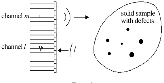
This method is composed of two steps: the first step of this technique consists of measuring the L×L inter-element impulse responses
k
lm(
t
)
of the array insonifying a solid sample ( see figure 4). For this measurement, the first element is excited by a short pulsee
(
t
)
and the received signals are measured by each the L elements. This operation is repeated for each element with the same emissione
(
t
)
. Then, the transfer matrix K is obtained by Fourier transforming the responsesk
lm(
t
)
. The time reversal operatorK
*K
can be diagonalized and as shown above, when the medium contains several pointlike scatterers, the number of significant eigenvalues is equal to the number of well-resolved scatterers. Furthermore, each eigenvector provides phase and amplitude information that should be applied to the transducer array in order to focus on each scatterer and each eigenvalue is a function of the strength of the scatterers, with the largest eigenvalue corresponding to the strongest scatterer.Once all the significative eigenvalues and eigenvectors have been computed, synthetic images of the sample are obtained by a numerical backpropagation of each significant eigenvector. This backpropagation is calculated using the simulation code P.A.S.S. that takes into account the geometry of the transducers as well as the solid-liquid interface [19].
solid sample
with defects
channel
m
[image:6.596.155.440.353.497.2]channel
l
Figure 4
REFERENCES
[1]
P. J. Howard, D. C. Copley, J. D. Young, E. J. Nieters and R. S. Gilmore “An improved methodology for the inspection of titanium alloys,” IEEE Ultrason. Symp. Proc., pp. 727-730 (1996).
[2]
V. Lupien, F. Cancre, “Ultrasonic phased array inspection of titanium billets,” in Rev. of Prog. in QNDE Vol. 20, edited by D. O. Thompson and D. E. Chimenti, pp. 919-926 (2001).
[3]
S. W. Flax and M. O’Donnell, “Phase-aberration correcting using signals from point reflectors and diffuse scatterers: Basic principles,” IEEE Trans. Ultrason. Ferroelec. Freq. Contr., vol. 35, no5, pp. 758-767 (1988).
[4]
B. Beardsley, M. Peterson and J. D. Achenbach, “A simple scheme for self focusing of an array”, Journal of NDE, vol. 14, n°4, pp. 169-179, Plenum Press (1996).
[5]
M. Fink, “Time reversal of ultrasonic fields-Part I: Basic principles,” IEEE Trans. Ultrason. Ferroelec. Freq. Contr., vol. 39, no5, pp. 555-566 (1992).
[6]
N. Chakroun, M. Fink and F. Wu, “Time reversal processing in ultrasonic nondestructive testing,” IEEE Trans. Ultrason. Ferroelec. Freq. Contr., vol. 42, no6, pp. 1087-1098 (1995).
[7]
C. Prada, J.-L. Thomas and M. Fink, “The iterative time reversal process: Analysis of the convergence,” J. Acoust. Soc. Am. 97, (1), 62-71 (1995).
[8]