2.2 This is the Nearest One Head 669
c
h
a
p
t
e
r
Heat Engines, Entropy, and the
Second Law of Thermodynamics
P
U Z Z L E R
The purpose of a refrigerator is to keep its contents cool. Beyond the attendant increase in your electricity bill, there is another good reason you should not try to cool the kitchen on a hot day by leaving the refrigerator door open. What might this reason be? (Charles D. Winters)
C h a p t e r O u t l i n e
22.1 Heat Engines and the Second
Law of Thermodynamics
22.2 Reversible and Irreversible
Processes
22.3 The Carnot Engine
22.4 Gasoline and Diesel Engines
22.5 Heat Pumps and Refrigerators
22.6 Entropy
22.7 Entropy Changes in Irreversible
Processes
22.8 (Optional)Entropy on a Microscopic Scale
P
U Z Z L E R
he first law of thermodynamics, which we studied in Chapter 20, is a state-ment of conservation of energy, generalized to include internal energy. This law states that a change in internal energy in a system can occur as a result of energy transfer by heat or by work, or by both. As was stated in Chapter 20, the law makes no distinction between the results of heat and the results of work — either heat or work can cause a change in internal energy. However, an important distinc-tion between the two is not evident from the first law. One manifestadistinc-tion of this distinction is that it is impossible to convert internal energy completely to mechan-ical energy by taking a substance through a thermodynamic cycle such as in a heat engine,a device we study in this chapter.
Although the first law of thermodynamics is very important, it makes no dis-tinction between processes that occur spontaneously and those that do not. How-ever, we find that only certain types of energy-conversion and energy-transfer processes actually take place. The second law of thermodynamics,which we study in this chapter, establishes which processes do and which do not occur in nature. The following are examples of processes that proceed in only one direction, governed by the second law:
• When two objects at different temperatures are placed in thermal contact with each other, energy always flows by heat from the warmer to the cooler, never from the cooler to the warmer.
• A rubber ball dropped to the ground bounces several times and eventually comes to rest, but a ball lying on the ground never begins bouncing on its own.
• An oscillating pendulum eventually comes to rest because of collisions with air molecules and friction at the point of suspension. The mechanical energy of the system is converted to internal energy in the air, the pendulum, and the suspen-sion; the reverse conversion of energy never occurs.
All these processes are irreversible— that is, they are processes that occur natu-rally in one direction only. No irreversible process has ever been observed to run backward — if it were to do so, it would violate the second law of thermodynamics.1 From an engineering standpoint, perhaps the most important implication of the second law is the limited efficiency of heat engines. The second law states that a machine capable of continuously converting internal energy completely to other forms of energy in a cyclic process cannot be constructed.
HEAT ENGINES AND THE SECOND LAW
OF THERMODYNAMICS
A heat engineis a device that converts internal energy to mechanical energy. For instance, in a typical process by which a power plant produces electricity, coal or some other fuel is burned, and the high-temperature gases produced are used to convert liquid water to steam. This steam is directed at the blades of a turbine, set-ting it into rotation. The mechanical energy associated with this rotation is used to drive an electric generator. Another heat engine — the internal combustion en-gine in an automobile — uses energy from a burning fuel to perform work that re-sults in the motion of the automobile.
22.1
T
10.8
22.1 Heat Engines and the Second Law of Thermodynamics 671
A heat engine carries some working substance through a cyclic process during which (1) the working substance absorbs energy from a high-temperature energy reservoir, (2) work is done by the engine, and (3) energy is expelled by the engine to a lower-temperature reservoir. As an example, consider the operation of a steam engine (Fig. 22.1), in which the working substance is water. The water in a boiler absorbs energy from burning fuel and evaporates to steam, which then does work by expanding against a piston. After the steam cools and condenses, the liquid wa-ter produced returns to the boiler and the cycle repeats.
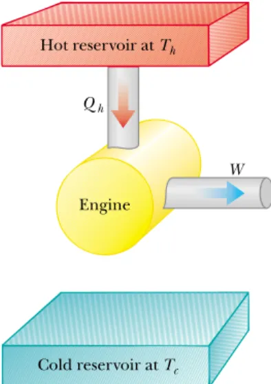
It is useful to represent a heat engine schematically as in Figure 22.2. The en-gine absorbs a quantity of energy Qh from the hot reservoir, does work W, and then gives up a quantity of energy Qcto the cold reservoir. Because the working substance goes through a cycle, its initial and final internal energies are equal, and so Hence, from the first law of thermodynamics, and with no change in internal energy, the net work W done by a heat engine is equal to the net energy Qnet flowing through it. As we can see from Figure
22.2, therefore,
(22.1)
In this expression and in many others throughout this chapter, to be consistent with traditional treatments of heat engines, we take both Qhand Qcto be positive quantities, even though Qcrepresents energy leaving the engine. In discussions of heat engines, we shall describe energy leaving a system with an explicit minus sign,
WQhQc
QnetQhQc;
EintQW,
Eint0.
Lord Kelvin
British physicist and mathematician (1824 – 1907) Born William Thomson in Belfast, Kelvin was the first to propose the use of an absolute scale of temperature. The Kelvin temperature scale is named in his honor. Kelvin’s work in thermo-dynamics led to the idea that energy cannot pass spontaneously from a colder body to a hotter body. (J. L. Charmet /SPL /Photo Researchers, Inc.)Hot reservoir at Th
Qh
Qc
W
Cold reservoir at Tc
Engine
Figure 22.1 This steam-driven locomotive runs from Durango to Silverton, Colorado. It ob-tains its energy by burning wood or coal. The generated energy vaporizes water into steam, which powers the locomotive. (This locomotive must take on water from tanks located along the route to replace steam lost through the funnel.) Modern locomotives use diesel fuel instead of wood or coal. Whether old-fashioned or modern, such locomotives are heat engines, which extract energy from a burning fuel and convert a fraction of it to mechanical energy.
Figure 22.2 Schematic represen-tation of a heat engine. The engine absorbs energy Qhfrom the hot
reservoir, expels energy Qcto the
as in Equation 22.1. Also note that we model the energy input and output for the heat engine as heat, as it often is; however, the energy transfer could occur by an-other mechanism.
The net work done in a cyclic process is the area enclosed by the curve representing the process on a PVdiagram.This is shown for an arbitrary cyclic process in Figure 22.3.
The thermal efficiency e of a heat engine is defined as the ratio of the net work done by the engine during one cycle to the energy absorbed at the higher temperature during the cycle:
(22.2)
e W
Qh
QhQc
Qh
1 Qc
Qh
We can think of the efficiency as the ratio of what you get (mechanical work) to what you give (energy transfer at the higher temperature). In practice, we find that all heat engines expel only a fraction of the absorbed energy as mechanical work and that consequently the efficiency is less than 100%. For example, a good automobile engine has an efficiency of about 20%, and diesel engines have effi-ciencies ranging from 35% to 40%.
Equation 22.2 shows that a heat engine has 100% efficiency (e1) only if
Qc0 — that is, if no energy is expelled to the cold reservoir. In other words, a heat engine with perfect efficiency would have to expel all of the absorbed energy as mechanical work. On the basis of the fact that efficiencies of real engines are well below 100%, the Kelvin – Planckform of the second law of thermodynam-icsstates the following:
It is impossible to construct a heat engine that, operating in a cycle, produces no effect other than the absorption of energy from a reservoir and the perfor-mance of an equal amount of work.
Kelvin–Planck statement of the second law of thermodynamics
P
V
Area = W
Figure 22.3 PVdiagram for an arbitrary cyclic process. The value of the net work done equals the area enclosed by the curve.
This statement of the second law means that, during the operation of a heat en-gine, Wcan never be equal to Qh, or, alternatively, that some energy Qcmust be
The impossible engine
Qh
Cold reservoir at Tc
Engine
W
Hot reservoir at Th
Figure 22.4 Schematic diagram of a heat engine that absorbs energy Qhfrom a hot reservoir and does
22.1 Heat Engines and the Second Law of Thermodynamics 673 rejected to the environment. Figure 22.4 is a schematic diagram of the impossible
“perfect” heat engine.
The first and second laws of thermodynamics can be summarized as follows: The first law specifies that we cannot get more energy out of a cyclic process by work than the amount of energy we put in, and the second law states that
we cannot break even because we must put more energy in, at the higher temperature, than the net amount of energy we get out by work.
The Efficiency of an Engine
E
XAMPLE22.1
Equation 22.2:
or 25% e1 Qc
Qh
1 1 500 J
2 000 J 0.25, Find the efficiency of a heat engine that absorbs 2 000 J of
energy from a hot reservoir and exhausts 1 500 J to a cold reservoir.
Solution
To calculate the efficiency of the engine, we useRefrigerators and Heat Pumps
Refrigeratorsand heat pumpsare heat engines running in reverse. Here, we in-troduce them briefly for the purposes of developing an alternate statement of the second law; we shall discuss them more fully in Section 22.5.
In a refrigerator or heat pump, the engine absorbs energy Qc from a cold reservoir and expels energy Qhto a hot reservoir (Fig. 22.5). This can be accom-plished only if work is done onthe engine. From the first law, we know that the en-ergy given up to the hot reservoir must equal the sum of the work done and the energy absorbed from the cold reservoir. Therefore, the refrigerator or heat pump transfers energy from a colder body (for example, the contents of a kitchen refrig-erator or the winter air outside a building) to a hotter body (the air in the kitchen or a room in the building). In practice, it is desirable to carry out this process with a minimum of work. If it could be accomplished without doing any work, then the refrigerator or heat pump would be “perfect” (Fig. 22.6). Again, the existence of
Refrigerator
Qh
Qc
Cold reservoir at Tc
Engine
W
Hot reservoir at Th
Impossible refrigerator Cold reservoir at Tc
Engine Hot reservoir at Th
Figure 22.5 Schematic diagram of a refrigerator, which absorbs energy Qcfrom a cold reservoir and
ex-pels energy Qhto a hot reservoir. Work Wis done onthe
refrigerator. A heat pump, which can be used to heat or cool a building, works the same way.
Figure 22.6 Schematic diagram of an impossible refrigerator or heat pump — that is, one that ab-sorbs energy Qcfrom a cold
such a device would be in violation of the second law of thermodynamics, which in the form of the Clausius statement2states:
It is impossible to construct a cyclical machine whose sole effect is the continu-ous transfer of energy from one object to another object at a higher tempera-ture without the input of energy by work.
In simpler terms, energy does not flow spontaneously from a cold object to a hot object.For example, we cool homes in summer using heat pumps called air conditioners.The air conditioner pumps energy from the cool room in the home to the warm air outside. This direction of energy transfer requires an input of energy to the air conditioner, which is supplied by the electric power company.
The Clausius and Kelvin – Planck statements of the second law of thermody-namics appear, at first sight, to be unrelated, but in fact they are equivalent in all respects. Although we do not prove so here, if either statement is false, then so is the other.3
REVERSIBLE AND IRREVERSIBLE PROCESSES
In the next section we discuss a theoretical heat engine that is the most efficient possible. To understand its nature, we must first examine the meaning of re-versible and irrere-versible processes. In a reversibleprocess, the system undergoing the process can be returned to its initial conditions along the same path shown on a PVdiagram, and every point along this path is an equilibrium state. A process that does not satisfy these requirements is irreversible.
All natural processes are known to be irreversible. From the endless number of examples that could be selected, let us examine the adiabatic free expansion of a gas, which was already discussed in Section 20.6, and show that it cannot be re-versible. The system that we consider is a gas in a thermally insulated container, as shown in Figure 22.7. A membrane separates the gas from a vacuum. When the membrane is punctured, the gas expands freely into the vacuum. As a result of the puncture, the system has changed because it occupies a greater volume after the expansion. Because the gas does not exert a force through a distance on the surroundings, it does no work on the surroundings as it expands. In addition, no energy is transferred to or from the gas by heat because the container is insulated from its surroundings. Thus, in this adiabatic process, the system has changed but the surroundings have not.
For this process to be reversible, we need to be able to return the gas to its original volume and temperature without changing the surroundings. Imagine that we try to reverse the process by compressing the gas to its original volume. To do so, we fit the container with a piston and use an engine to force the piston in-ward. During this process, the surroundings change because work is being done by an outside agent on the system. In addition, the system changes because the com-pression increases the temperature of the gas. We can lower the temperature of the gas by allowing it to come into contact with an external energy reservoir. Al-though this step returns the gas to its original conditions, the surroundings are
22.2
Clausius statement of the second law of thermodynamics
2First expressed by Rudolf Clausius (1822 – 1888).
3See, for example, R. P. Bauman, Modern Thermodynamics and Statistical Mechanics,New York, Macmillan Publishing Co., 1992.
Insulating wall
Membrane Vacuum
Gas at Ti
22.3 The Carnot Engine 675
again affected because energy is being added to the surroundings from the gas. If this energy could somehow be used to drive the engine that we have used to com-press the gas, then the net energy transfer to the surroundings would be zero. In this way, the system and its surroundings could be returned to their initial condi-tions, and we could identify the process as reversible. However, the Kelvin – Planck statement of the second law specifies that the energy removed from the gas to re-turn the temperature to its original value cannot be completely converted to me-chanical energy in the form of the work done by the engine in compressing the gas. Thus, we must conclude that the process is irreversible.
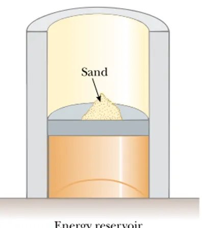
We could also argue that the adiabatic free expansion is irreversible by relying on the portion of the definition of a reversible process that refers to equilibrium states. For example, during the expansion, significant variations in pressure occur throughout the gas. Thus, there is no well-defined value of the pressure for the en-tire system at any time between the initial and final states. In fact, the process cannot even be represented as a path on a PVdiagram. The PV diagram for an adiabatic free expansion would show the initial and final conditions as points, but these points would not be connected by a path. Thus, because the intermediate conditions be-tween the initial and final states are not equilibrium states, the process is irreversible. Although all real processes are always irreversible, some are almost reversible. If a real process occurs very slowly such that the system is always very nearly in an equilibrium state, then the process can be approximated as reversible. For exam-ple, let us imagine that we compress a gas very slowly by dropping some grains of sand onto a frictionless piston, as shown in Figure 22.8. We make the process isothermal by placing the gas in thermal contact with an energy reservoir, and we transfer just enough energy from the gas to the reservoir during the process to keep the temperature constant. The pressure, volume, and temperature of the gas are all well defined during the isothermal compression, so each state during the process is an equilibrium state. Each time we add a grain of sand to the piston, the volume of the gas decreases slightly while the pressure increases slightly. Each grain we add represents a change to a new equilibrium state. We can reverse the process by slowly removing grains from the piston.
A general characteristic of a reversible process is that no dissipative effects (such as turbulence or friction) that convert mechanical energy to internal energy can be present. Such effects can be impossible to eliminate completely. Hence, it is not surprising that real processes in nature are irreversible.
THE CARNOT ENGINE
In 1824 a French engineer named Sadi Carnot described a theoretical engine, now called a Carnot engine, that is of great importance from both practical and theoretical viewpoints. He showed that a heat engine operating in an ideal, re-versible cycle — called a Carnot cycle— between two energy reservoirs is the most efficient engine possible. Such an ideal engine establishes an upper limit on the efficiencies of all other engines. That is, the net work done by a working substance taken through the Carnot cycle is the greatest amount of work possible for a given amount of energy supplied to the substance at the upper temperature. Carnot’s theoremcan be stated as follows:
22.3
Figure 22.8 A gas in thermal contact with an energy reservoir is compressed slowly as individual grains of sand drop onto the pis-ton. The compression is isothermal and reversible.
Energy reservoir Sand
No real heat engine operating between two energy reservoirs can be more effi-cient than a Carnot engine operating between the same two reservoirs.
Sadi Carnot
French physicist (1796 – 1832) Carnot was the first to show the quantitative relationship be-tween work and heat. In 1824 he pub-lished his only work —Reflections on the Motive Power of Heat—which reviewed the industrial, political, and economic importance of the steam engine. In it, he defined work as “weight lifted through a height.” (FPG)To argue the validity of this theorem, let us imagine two heat engines operating between the sameenergy reservoirs. One is a Carnot engine with efficiency eC, and the other is an engine with efficiency e, which is greater than eC. We use the more efficient engine to drive the Carnot engine as a Carnot refrigerator. Thus, the out-put by work of the more efficient engine is matched to the inout-put by work of the
Cycle
D→A
Adiabatic compression
Q = 0
(d)
B→C
Adiabatic expansion
Q = 0
(b) Energy reservoir at Th
(a)
A→B
Isothermal expansion
(c) Energy reservoir at Tc
C→D
Isothermal compression
Qh
Qc
Figure 22.9 The Carnot cycle. In process A:B, the gas expands isothermally while in contact with a reservoir at Th. In process B:C, the gas expands adiabatically (Q0). In process C:D,
the gas is compressed isothermally while in contact with a reservoir at In process D:A, the gas is compressed adiabatically. The upward arrows on the piston indicate that weights are be-ing removed durbe-ing the expansions, and the downward arrows indicate that weights are bebe-ing added during the compressions.
22.3 The Carnot Engine 677 Carnot refrigerator. For the combination of the engine and refrigerator, then, no
exchange by work with the surroundings occurs. Because we have assumed that the engine is more efficient than the refrigerator, the net result of the combina-tion is a transfer of energy from the cold to the hot reservoir without work being done on the combination. According to the Clausius statement of the second law, this is impossible. Hence, the assumption that must be false. All real en-gines are less efficient than the Carnot engine because they do not operate through a reversible cycle.The efficiency of a real engine is further reduced by such practical difficulties as friction and energy losses by conduction.
To describe the Carnot cycle taking place between temperatures Tcand Th, we assume that the working substance is an ideal gas contained in a cylinder fitted with a movable piston at one end. The cylinder’s walls and the piston are ther-mally nonconducting. Four stages of the Carnot cycle are shown in Figure 22.9, and the PV diagram for the cycle is shown in Figure 22.10. The Carnot cycle con-sists of two adiabatic processes and two isothermal processes, all reversible:
1. Process A:B(Fig. 22.9a) is an isothermal expansion at temperature Th. The gas is placed in thermal contact with an energy reservoir at temperature Th. During the expansion, the gas absorbs energy Qh from the reservoir through the base of the cylinder and does work WABin raising the piston.
2. In process B:C (Fig. 22.9b), the base of the cylinder is replaced by a ther-mally nonconducting wall, and the gas expands adiabatically — that is, no en-ergy enters or leaves the system. During the expansion, the temperature of the gas decreases from Th to Tc and the gas does work WBC in raising the piston.
3. In process C:D(Fig. 22.9c), the gas is placed in thermal contact with an en-ergy reservoir at temperature Tcand is compressed isothermally at temperature
Tc. During this time, the gas expels energy Qcto the reservoir, and the work done by the piston on the gas is WC D.
4. In the final process D:A(Fig. 22.9d), the base of the cylinder is replaced by a nonconducting wall, and the gas is compressed adiabatically. The temperature of the gas increases to Th, and the work done by the piston on the gas is WDA.
The net work done in this reversible, cyclic process is equal to the area en-closed by the path ABC DAin Figure 22.10. As we demonstrated in Section 22.1, because the change in internal energy is zero, the net work Wdone in one cycle equals the net energy transferred into the system, QhQc. The thermal efficiency of the engine is given by Equation 22.2:
In Example 22.2, we show that for a Carnot cycle
(22.3)
Hence, the thermal efficiency of a Carnot engine is
(22.4)
This result indicates that all Carnot engines operating between the same two temperatures have the same efficiency.
eC1
Tc
Th
Qc
Qh
Tc
Th
e W
Qh
QhQc
Qh
1 Qc
Qh
eeC
Ratio of energies for a Carnot cycle
Efficiency of a Carnot engine
V P
A
C B
D
Qc
Qh
Th
Tc
W
Figure 22.10 PVdiagram for the Carnot cycle. The net work done,
W, equals the net energy received in one cycle, Note that
for the cycle.
Eint0
Efficiency of the Carnot Engine
E
XAMPLE22.2
pression for Pand substituting into (2), we obtain
which we can write as
where we have absorbed nRinto the constant right-hand side. Applying this result to the adiabatic processes B:C and D:A, we obtain
Dividing the first equation by the second, we obtain
(3)
Substituting (3) into (1), we find that the logarithmic terms cancel, and we obtain the relationship
Using this result and Equation 22.2, we see that the thermal efficiency of the Carnot engine is
which is Equation 22.4, the one we set out to prove. eC1
Qc Qh
1 Tc Th Qc
Qh Tc
Th VB
VA VC VD
(VB/VA)1(VC/VD)1 ThVA1TcVD1 ThVB1TcVC1 TV1constant nRT
V V
constant
Show that the efficiency of a heat engine operating in a Carnot cycle using an ideal gas is given by Equation 22.4.
Solution
During the isothermal expansion (process A:Bin Figure 22.9), the temperature does not change. Thus, the internal energy remains constant. The work done by a gas during an isothermal expansion is given by Equation 20.13. According to the first law, this work is equal to Qh, the energy
absorbed, so that
In a similar manner, the energy transferred to the cold reser-voir during the isothermal compression C:Dis
We take the absolute value of the work because we are defin-ing all values of Qfor a heat engine as positive, as mentioned earlier. Dividing the second expression by the first, we find that
(1)
We now show that the ratio of the logarithmic quantities is unity by establishing a relationship between the ratio of vol-umes. For any quasi-static, adiabatic process, the pressure and volume are related by Equation 21.18:
(2)
During any reversible, quasi-static process, the ideal gas must also obey the equation of state, PVnRT. Solving this
ex-PVconstant Qc
Qh Tc Th
ln(VC/VD)
ln(VB/VA) Qc兩WCD兩nRTc ln
VC VD QhWABnRTh ln
VB VA
The Steam Engine
E
XAMPLE22.3
Solution
Using Equation 22.4, we find that the maximumthermal efficiency for any engine operating between these temperatures is
or 40% eC1
Tc Th
1 300 K 500 K 0.4, A steam engine has a boiler that operates at 500 K. The
en-ergy from the burning fuel changes water to steam, and this steam then drives a piston. The cold reservoir’s temperature is that of the outside air, approximately 300 K. What is the maximum thermal efficiency of this steam engine?
Equation 22.4 can be applied to any working substance operating in a Carnot cycle between two energy reservoirs. According to this equation, the efficiency is zero if as one would expect. The efficiency increases as Tcis lowered and as This raised. However, the efficiency can be unity (100%) only if K. Such reservoirs are not available; thus, the maximum efficiency is always less than 100%. In most practical cases, Tcis near room temperature, which is about 300 K. There-fore, one usually strives to increase the efficiency by raising Th.
Tc0
22.4 Gasoline and Diesel Engines 679
GASOLINE AND DIESEL ENGINES
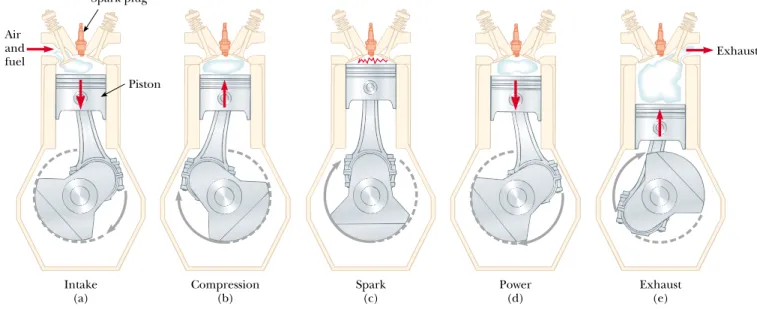
In a gasoline engine, six processes occur in each cycle; five of these are illustrated in Figure 22.11. In this discussion, we consider the interior of the cylinder above the piston to be the system that is taken through repeated cycles in the operation of the engine. For a given cycle, the piston moves up and down twice. This repre-sents a four-stroke cycle consisting of two upstrokes and two downstrokes. The processes in the cycle can be approximated by the Otto cycle, a PV diagram of which is illustrated in Figure 22.12:
1. During the intake stroke O:A(Fig. 22.11a), the piston moves downward, and a gaseous mixture of air and fuel is drawn into the cylinder at atmospheric pres-sure. In this process, the volume increases from V2to V1. This is the energy in-put part of the cycle, as energy enters the system (the interior of the cylinder) as internal energy stored in the fuel. This is energy transfer by mass transfer— that is, the energy is carried with a substance. It is similar to convection, which we studied in Chapter 20.
2. During the compression stroke A:B(Fig. 22.11b), the piston moves upward, the air – fuel mixture is compressed adiabatically from volume V1to volume V2, and the temperature increases from TAto TB. The work done by the gas is negative, and its value is equal to the area under the curve AB in Figure 22.12.
3. In process B:C, combustion occurs when the spark plug fires (Fig. 22.11c). This is not one of the strokes of the cycle because it occurs in a very short period of time while the piston is at its highest position. The combustion repre-sents a rapid transformation from internal energy stored in chemical bonds in the fuel to internal energy associated with molecular motion, which is related to temperature. During this time, the pressure and temperature in the cylinder increase rapidly, with the temperature rising from TB to TC. The volume, how-ever, remains approximately constant because of the short time interval. As a re-sult, approximately no work is done by the gas. We can model this process in the PV diagram (Fig. 22.12) as that process in which the energy Qhenters the system. However, in reality this process is a transformation of energy already in the cylinder (from process O:A) rather than a transfer.
4. In the power stroke C:D(Fig. 22.11d), the gas expands adiabatically from V2to
22.4
The Carnot Efficiency
E
XAMPLE22.4
430K Th
Tc
1eC
300 K 10.30 eC1
Tc Th
The highest theoretical efficiency of a certain engine is 30%.
If this engine uses the atmosphere, which has a temperature of 300 K, as its cold reservoir, what is the temperature of its hot reservoir?
Solution
We use the Carnot efficiency to find Th:You should note that this is the highest theoreticalefficiency of the engine. In practice, the efficiency is considerably lower.
Exercise
Determine the maximum work that the enginecan perform in each cycle if it absorbs 200 J of energy from the hot reservoir during each cycle.
V1. This expansion causes the temperature to drop from TC to TD. Work is done by the gas in pushing the piston downward, and the value of this work is equal to the area under the curve CD.
5. In the process D:A(not shown in Fig. 22.11), an exhaust valve is opened as the piston reaches the bottom of its travel, and the pressure suddenly drops for a short time interval. During this interval, the piston is almost stationary and the volume is approximately constant. Energy is expelled from the interior of the cylinder and continues to be expelled during the next process.
6. In the final process, the exhaust stroke A:O(Fig. 22.11e), the piston moves up-ward while the exhaust valve remains open. Residual gases are exhausted at at-mospheric pressure, and the volume decreases from V1 to V2. The cycle then repeats.
If the air – fuel mixture is assumed to be an ideal gas, then the efficiency of the Otto cycle is
(22.5)
where is the ratio of the molar specific heats CP/CVfor the fuel – air mixture and
V1/V2is the compression ratio. Equation 22.5, which we derive in Example 22.5, shows that the efficiency increases as the compression ratio increases. For a typical compression ratio of 8 and with 1.4, we predict a theoretical efficiency of 56% for an engine operating in the idealized Otto cycle. This value is much greater than that achieved in real engines (15% to 20%) because of such effects as fric-tion, energy transfer by conduction through the cylinder walls, and incomplete combustion of the air – fuel mixture.
Diesel engines operate on a cycle similar to the Otto cycle but do not employ a spark plug. The compression ratio for a diesel engine is much greater than that
e1 1
(V1/V2)1 Efficiency of the Otto cycle
Air and fuel
Spark plug
Piston
Intake (a)
Compression (b)
Spark (c)
Power (d)
Exhaust
Exhaust (e)
Figure 22.11 The four-stroke cycle of a conventional gasoline engine. (a) In the intake stroke, air is mixed with fuel. (b) The intake valve is then closed, and the air – fuel mixture is compressed by the piston. (c) The mixture is ignited by the spark plug, with the result that the temperature of the mixture increases. (d) In the power stroke, the gas expands against the pis-ton. (e) Finally, the residual gases are expelled, and the cycle repeats.
P
V V1 V2
A
B D
C
O Qh
Qc
Adiabatic processes
22.4 Gasoline and Diesel Engines 681
Efficiency of the Otto Cycle
E
XAMPLE22.5
and we find that
(2)
(3)
Subtracting (2) from (3) and rearranging, we find that
(4)
Substituting (4) into (1), we obtain for the thermal efficiency
(5)
which is Equation 22.5.
We can also express this efficiency in terms of tempera-tures by noting from (2) and (3) that
Therefore, (5) becomes
(6)
During the Otto cycle, the lowest temperature is TAand the
highest temperature is TC. Therefore, the efficiency of a
Carnot engine operating between reservoirs at these two temperatures, which is given by the expression
is greaterthan the efficiency of the Otto cycle given by (6), as expected.
1(TA/TC),
eC e1 TA
TB
1 TD TC
冢
V2 V1冣
1 TA
TB TD TC
e1 1
(V1/V2)1 TDTA
TCTB
冢
V2 V1冣
1 TDTC
冢
V2 V1
冣
1 TDV11TCV21
TATB
冢
V2 V1冣
1 TAV11TBV21
VBVCV2, VAVDV1
Show that the thermal efficiency of an engine operating in an idealized Otto cycle (see Figs. 22.11 and 22.12) is given by Equation 22.5. Treat the working substance as an ideal gas.
Solution
First, let us calculate the work done by the gasduring each cycle. No work is done during processes B:C and D:A. The work done by the gas during the adiabatic compression A:Bis negative, and the work done by the gas during the adiabatic expansion C:Dis positive. The value of the net work done equals the area of the shaded region bounded by the closed curve in Figure 22.12. Because the change in internal energy for one cycle is zero, we see from the first law that the net work done during one cycle equals the net energy flow through the system:
WQhQc
Because processes B:C and D:Atake place at constant volume, and because the gas is ideal, we find from the defini-tion of molar specific heat (Eq. 21.8) that
and
Using these expressions together with Equation 22.2, we ob-tain for the thermal efficiency
(1)
We can simplify this expression by noting that processes A:Band C:Dare adiabatic and hence obey the relation-ship which we obtained in Example 22.2. For the two adiabatic processes, then,
A:B: C:D:
Using these equations and relying on the fact that TCVC1TDVD1
TAVA1TBVB1 TV1constant,
e W Qh
1 Qc Qh
1 TDTA TCTB QcnCV(TDTA) QhnCV(TCTB)
for a gasoline engine. Air in the cylinder is compressed to a very small volume, and, as a consequence, the cylinder temperature at the end of the compression stroke is very high. At this point, fuel is injected into the cylinder. The temperature is high enough for the fuel – air mixture to ignite without the assistance of a spark plug. Diesel engines are more efficient than gasoline engines because of their greater compression ratios and resulting higher combustion temperatures.
Models of Gasoline and Diesel Engines
A
PPLICATIONmixture as the products of combustion expand in the cylinder. The power of the engine is transferred from the piston to the crankshaft by the connecting rod.
Two important quantities of either engine are the displace-ment volume,which is the volume displaced by the piston as it moves from the bottom to the top of the cylinder, and the com-We can use the thermodynamic principles discussed in this
We also know that the difference in volumes is the displace-ment volume. The 3.00-L rating of the engine is the total displacement volume for all six cylinders. Thus, for one cylinder,
Solving these two equations simultaneously, we find the initial and final volumes:
Using the ideal gas law (in the form PVmRT, because we are using the universal gas constant in terms of mass rather than moles), we can find the mass of the air – fuel mixture:
Process A:B (see Fig. 22.12) is an adiabatic compression, and this means that hence,
Using the ideal gas law, we find that the temperature after the compression is
In process B:C, the combustion that transforms the in-ternal energy in chemical bonds into inin-ternal energy of mo-lecular motion occurs at constant volume; thus, VCVB.
Combustion causes the temperature to increase to TC
1 350°C1 623 K . Using this value and the ideal gas law, we can calculate PC:
Process C:D is an adiabatic expansion; the pressure after the expansion is
(5.14103 kPa)
冢
19.50
冣
1.40
220 kPa PDPC
冢
VC VD
冣
PC
冢
VB VA冣
PC
冢
1 r
冣
5.14103 kPa
(6.49104 kg)(0.287 kPam3/kgK)(1 623 K) (0.588104 m3)
PC mRTC
VC 739 K TB
PBVB
mR
(2.34103 kPa)(0.588104 m3) (6.49104 kg)(0.287 kPam3/kgK) 2.34103 kPa
PBPA
冢
VA VB冣
PA(r)(100 kPa)(9.50)1.40 PBVBPAVA
PVconstant; 6.49104 kg m PAVA
RTA
(100 kPa)(0.559103 m3)
(0.287 kPam3/kgK)(300 K) VA0.559103 m3
VB0.588104 m3 VAVB
3.00 L
6
3.00103 m3
6 0.500 10
3 m3 VA
VB
r9.50
pression ratior, which is the ratio of the maximum and mini-mum volumes of the cylinder (see p. 680). In our notation, rVA/VB, or V1/V2in Eq. 22.5. Most gasoline and diesel
en-gines operate with a four-cycle process (intake, compression, power, exhaust), in which the net work of the intake and ex-haust cycles can be considered negligible. Therefore, power is developed only once for every two revolutions of the crank-shaft.
In a diesel engine, only air (and no fuel) is present in the cylinder at the beginning of the compression. In the ideal-ized diesel cycle of Figure 22.13, air in the cylinder under-goes an adiabatic compression from Ato B. Starting at B, fuel is injected into the cylinder in such a way that the fuel – air mixture undergoes a constant-pressure expansion to an inter-mediate volume VC(B:C). The high temperature of the
mixture causes combustion, and the power stroke is an adia-batic expansion back to VDVA(C:D). The exhaust valve
is opened, and a constant-volume output of energy occurs (D:A) as the cylinder empties.
To simplify our calculations, we assume that the mixture in the cylinder is air modeled as an ideal gas. We use specific heats c instead of molar specific heats C and assume con-stant values for air at 300 K. We express the specific heats and the universal gas constant in terms of unit masses rather than moles. Thus, cV0.718 kJ/kgK, cP1.005 kJ/kgK ,
and kJ/kgK
.
A 3.00-L Gasoline Engine
Let us calculate the power delivered by a six-cylinder gasoline engine that has a displacement volume of 3.00 L operating at 4 000 rpm and having a compression ratio of r9.50. The air – fuel mixture enters a cylinder at atmospheric pressure and an ambient temperature of 27°C. During combustion, the mixture reaches a temperature of 1 350°C.
First, let us calculate the work done by an individual cylin-der. Using the initial pressure kPa and the initial temperature K , we calculate the initial volume and the mass of the air – fuel mixture. We know that the ratio of the initial and final volumes is the compression ratio,
TA300
PA100
0.287 kPam3/kgK
0.287 RcPcV cP/cV1.40,
Adiabatic processes A B C D P V Qh Qc
V2 = VB VC V1 = VA
22.4 Gasoline and Diesel Engines 683
Process A:B is an adiabatic compression, so con-stant; thus,
Using the ideal gas law, we find that the temperature of the air after the compression is
Process B:C is a constant-pressure expansion; thus, We know from the cutoff ratio of 2.00 that the vol-ume doubles in this process. According to the ideal gas law, a doubling of volume in an isobaric process results in a dou-bling of the temperature, so
Process C:Dis an adiabatic expansion; therefore,
We find the temperature at Dfrom the ideal gas law:
Now that we have the temperatures at the beginning and the end of each process, we can calculate the net energy transfer by heat and the net work done by each cylinder every two cy-cles:
The efficiency is
The net power for the four-cylinder engine operating at 3 000 rpm is
(3 000 rev/min) (1 min/60 s) (0.396 kJ)
39.6 kW53 hp
Of course, modern engine design goes beyond this simple thermodynamic treatment, which uses idealized cycles.
ᏼnet4
冢
1 2 rev
冣
eWnet/Qin66%. WnetQinQout0.396 kJ
QcQoutmcV(TDTA)0.205 kJ QhQinmcP(TCTB)0.601 kJ 792 K
TD PDVD
mR
(264 kPa)(0.500103 m3) (5.81104 kg)(0.287 kPam3/kgK) (7.57103 kPa)
冢
2.0022.0
冣
1.40
264 kPa PDPC
冢
VC VD
冣
PC
冢
VC VBVB VD
冣
PC
冢
rc1 r
冣
TC2TB2.06103 K PCPB.
1.03103 K TB
PBVB
mR
(7.57103 kPa)(0.500103 m3)
冢
1 22.0冣
(5.81104 kg)(0.287 kPam3/kgK) PBPA冢
VA VB
冣
(100 kPa)(22.0)1.407.57103 kPa PBVBPAVA
PV Using the ideal gas law again, we find the final temperature:
Now that we have the temperatures at the beginning and end of each process of the cycle, we can calculate the net en-ergy transfer and net work done by each cylinder every two cycles. From Equation 21.8, we can state
From Equation 22.2, the efficiency is
(We can also use Equation 22.5 to calculate the efficiency di-rectly from the compression ratio.)
Recalling that power is delivered every other revolution of the crankshaft, we find that the net power for the six-cylinder engine operating at 4 000 rpm is
(4 000 rev/min) (1 min/60 s) (0.244 kJ)
49 kW66 hp
A 2.00-L Diesel Engine
Let us calculate the power delivered by a four-cylinder diesel engine that has a displacement volume of 2.00 L and is operating at 3 000 rpm. The compression ratio is
, and the cutoff ratio, which is the ratio of the volume change during the constant-pressure process
in Figure 22.13, is The air enters each cylinder at the beginning of the compression cycle at at-mospheric pressure and at an ambient temperature of 27°C. Our model of the diesel engine is similar to our model of the gasoline engine except that now the fuel is injected at point Band the mixture self-ignites near the end of the com-pression cycle , when the temperature reaches the igni-tion temperature. We assume that the energy input occurs in the constant-pressure process , and that the expansion process continues from Cto Dwith no further energy transfer by heat.
Let us calculate the work done by an individual cylinder that has an initial volume of
Because the compression ratio is quite high, we approximate the maximum cylinder volume to be the displacement volume. Using the initial pressure PA
100 kPa and initial temperature TA300 K, we can calculate
the mass of the air in the cylinder using the ideal gas law: 0.500103 m3.
VA(2.00103 m3)/4 B:C
A:B
rcVC/VB2.00. B:C
rVA/VB22.0
ᏼnet6
冢
1 2 rev
冣
eWnet/Qin59%. WnetQinQout0.244 kJ
0.168 kJ
(6.49104 kg)(0.718 kJ/kgK)(660 K300 K) QcQoutmcV(TDTA)
0.412 kJ
(6.49104 kg)(0.718 kJ/kgK)(1 623 K739 K) QhQinmcV(TCTB)
660 K TD
PDVD
mR
(220 kPa)(0.559103 m3)
(6.49104 kg)(0.287 kPam3/kgK)
m PAVA RTA
(100 kPa)(0.500103 m3)
HEAT PUMPS AND REFRIGERATORS
In Section 22.1 we introduced a heat pump as a mechanical device that moves en-ergy from a region at lower temperature to a region at higher temperature. Heat pumps have long been used for cooling homes and buildings, and they are now becoming increasingly popular for heating them as well. The heat pump contains two sets of metal coils that can exchange energy by heat with the surroundings: one set on the outside of the building, in contact with the air or buried in the ground; and the other set in the interior of the building. In the heating mode, a circulating fluid flowing through the coils absorbs energy from the outside and re-leases it to the interior of the building from the interior coils. The fluid is cold and at low pressure when it is in the external coils, where it absorbs energy by heat from either the air or the ground. The resulting warm fluid is then compressed and enters the interior coils as a hot, high-pressure fluid, where it releases its stored energy to the interior air.
An air conditioner is simply a heat pump operating in the cooling mode, with its exterior and interior coils interchanged. Energy is absorbed into the circulating fluid in the interior coils; then, after the fluid is compressed, energy leaves the fluid through the external coils. The air conditioner must have a way to release en-ergy to the outside. Otherwise, the work done on the air conditioner would repre-sent energy added to the air inside the house, and the temperature would in-crease. In the same manner, a refrigerator cannot cool the kitchen if the refrigerator door is left open. The amount of energy leaving the external coils (Fig. 22.14) behind or underneath the refrigerator is greater than the amount of energy removed from the food or from the air in the kitchen if the door is left open. The difference between the energy out and the energy in is the work done by the electricity supplied to the refrigerator.
Figure 22.15 is a schematic representation of a heat pump. The cold tempera-ture is Tc, the hot temperature is Th, and the energy absorbed by the circulating fluid is Qc. The heat pump does work Won the fluid, and the energy transferred from the pump to the building in the heating mode is Qh.
The effectiveness of a heat pump is described in terms of a number called the
coefficient of performance(COP). In the heating mode, the COP is defined as the ratio of the energy transferred to the hot reservoir to the work required to transfer that energy:
(22.6)
Note that the COP is similar to the thermal efficiency for a heat engine in that it is a ratio of what you get (energy delivered to the interior of the building) to what you give (work input). Because Qhis generally greater than W, typical values for the COP are greater than unity. It is desirable for the COP to be as high as possible, just as it is desirable for the thermal efficiency of an engine to be as high as possible.
If the outside temperature is 25°F or higher, then the COP for a heat pump is about 4. That is, the amount of energy transferred to the building is about four times greater than the work done by the motor in the heat pump. However, as the outside temperature decreases, it becomes more difficult for the heat pump to ex-tract sufficient energy from the air, and so the COP decreases. In fact, the COP can fall below unity for temperatures below the midteens. Thus, the use of heat pumps that extract energy from the air, while satisfactory in moderate climates, is not appropriate in areas where winter temperatures are very low. It is possible to COP (heating mode)⬅ Energy transferred at high temperature
Work done by pump
Qh
W
22.5
22.6 Entropy 685 use heat pumps in colder areas by burying the external coils deep in the ground.
In this case, the energy is extracted from the ground, which tends to be warmer than the air in the winter.
In an electric heater, electrical energy can be converted to internal energy with an effi-ciency of 100%. By what percentage does the cost of heating your home change when you replace your electric heating system with a heat pump that has a COP of 4? Assume that the motor running the heat pump is 100% efficient.
Theoretically, a Carnot-cycle heat engine run in reverse constitutes the most effective heat pump possible, and it determines the maximum COP for a given combination of hot and cold reservoir temperatures. Using Equations 22.1 and 22.3, we see that the maximum COP for a heat pump in its heating mode is
For a heat pump operating in the cooling mode, “what you get” is energy re-moved from the cold reservoir. The most effective refrigerator or air conditioner is one that removes the greatest amount of energy from the cold reservoir in ex-change for the least amount of work. Thus, for these devices we define the COP in terms of Qc:
(22.7)
A good refrigerator should have a high COP, typically 5 or 6.
The greatest possible COP for a heat pump in the cooling mode is that of a heat pump whose working substance is carried through a Carnot cycle in reverse:
As the difference between the temperatures of the two reservoirs approaches zero in this expression, the theoretical COP approaches infinity. In practice, the low temperature of the cooling coils and the high temperature at the compressor limit the COP to values below 10.
ENTROPY
The zeroth law of thermodynamics involves the concept of temperature, and the first law involves the concept of internal energy. Temperature and internal energy are both state functions — that is, they can be used to describe the thermodynamic state of a system. Another state function — this one related to the second law of thermodynamics — is entropy S. In this section we define entropy on a macro-scopic scale as it was first expressed by Clausius in 1865.
22.6
COPC (cooling mode)
Tc
ThTc COP (cooling mode) Qc
W
Qh
QhQc
1
1 Qc
Qh
1
1 Tc
Th
Th
ThTc COPC(heating mode)
Qh
W
Quick Quiz 22.1
10.10 & 10.11
QuickLab
Estimate the COP of your refrigerator by making rough temperature mea-surements of the stored food and of the exhaust coils (found either on the back of the unit or behind a panel on the bottom). Use just your hand if no thermometer is available.
Hot reservoir at Th
Heat pump
Qh
Qc
Cold reservoir at Tc
W
Figure 22.15 Schematic diagram of a heat pump, which absorbs en-ergy Qcfrom a cold reservoir and
expels energy Qhto a hot reservoir.
Consider any infinitesimal process in which a system changes from one equi-librium state to another. If dQris the amount of energy transferred by heat when the system follows a reversible path between the states, then the change in entropy
dSis equal to this amount of energy for the reversible process divided by the ab-solute temperature of the system:
(22.8)
We have assumed that the temperature is constant because the process is infinitesi-mal. Since we have claimed that entropy is a state function, the change in en-tropy during a process depends only on the end points and therefore is in-dependent of the actual path followed.
The subscript ron the quantity dQris a reminder that the transferred energy is to be measured along a reversible path, even though the system may actually have followed some irreversible path. When energy is absorbed by the system, dQr is positive and the entropy of the system increases. When energy is expelled by the system, dQris negative and the entropy of the system decreases. Note that Equa-tion 22.8 defines not entropy but rather the change in entropy. Hence, the mean-ingful quantity in describing a process is the changein entropy.
Entropy was originally formulated as a useful concept in thermodynamics; however, its importance grew tremendously as the field of statistical mechanics de-veloped because the analytical techniques of statistical mechanics provide an alter-native means of interpreting entropy. In statistical mechanics, the behavior of a substance is described in terms of the statistical behavior of its atoms and mole-cules. One of the main results of this treatment is that isolated systems tend to-ward disorder and that entropy is a measure of this disorder.For example, consider the molecules of a gas in the air in your room. If half of the gas mole-cules had velocity vectors of equal magnitude directed toward the left and the other half had velocity vectors of the same magnitude directed toward the right, the situation would be very ordered. However, such a situation is extremely un-likely. If you could actually view the molecules, you would see that they move hap-hazardly in all directions, bumping into one another, changing speed upon colli-sion, some going fast and others going slowly. This situation is highly disordered. The cause of the tendency of an isolated system toward disorder is easily ex-plained. To do so, we distinguish between microstatesand macrostatesof a system. A
microstateis a particular description of the properties of the individual molecules of the system. For example, the description we just gave of the velocity vectors of the air molecules in your room being very ordered refers to a particular mi-crostate, and the more likely likely haphazard motion is another microstate — one that represents disorder. A macrostateis a description of the conditions of the sys-tem from a macroscopic point of view and makes use of macroscopic variables such as pressure, density, and temperature. For example, in both of the mi-crostates described for the air molecules in your room, the air molecules are dis-tributed uniformly throughout the volume of the room; this uniform density distri-bution is a macrostate. We could not distinguish between our two microstates by making a macroscopic measurement — both microstates would appear to be the same macroscopically, and the two macrostates corresponding to these microstates are equivalent.
For any given macrostate of the system, a number of microstates are possible, or accessible.Among these microstates, it is assumed that all are equally probable. However, when all possible microstates are examined, it is found that far more of them are disordered than are ordered. Because all of the microstates are equally
dS dQr
T
22.6 Entropy 687 probable, it is highly likely that the actual macrostate is one resulting from one of
the highly disordered microstates, simply because there are many more of them. Similarly, the probability of a macrostate’s forming from disordered microstates is greater than the probability of a macrostate’s forming from ordered microstates.
All physical processes that take place in a system tend to cause the system and its surroundings to move toward more probable macrostates. The more probable macrostate is always one of greater disorder. If we consider a system and its sur-roundings to include the entire Universe, then the Universe is always moving to-ward a macrostate corresponding to greater disorder. Because entropy is a mea-sure of disorder, an alternative way of stating this is the entropy of the Universe increases in all real processes.This is yet another statement of the second law of thermodynamics that can be shown to be equivalent to the Kelvin – Planck and Clausius statements.
To calculate the change in entropy for a finite process, we must recognize that
Tis generally not constant. If dQris the energy transferred by heat when the sys-tem is at a sys-temperature T, then the change in entropy in an arbitrary reversible process between an initial state and a final state is
(reversible path) (22.9)
As with an infinitesimal process, the change in entropy Sof a system going from one state to another has the same value for all paths connecting the two states. That is, the finite change in entropy Sof a system depends only on the properties of the initial and final equilibrium states. Thus, we are free to choose a particular reversible path over which to evaluate the entropy in place of the actual path, as long as the initial and final states are the same for both paths.
Which of the following is true for the entropy change of a system that undergoes a re-versible, adiabatic process? (a) S0. (b) S0. (c) S0.
Let us consider the changes in entropy that occur in a Carnot heat engine op-erating between the temperatures Tcand Th. In one cycle, the engine absorbs en-ergy Qhfrom the hot reservoir and expels energy Qcto the cold reservoir. These energy transfers occur only during the isothermal portions of the Carnot cycle; thus, the constant temperature can be brought out in front of the integral sign in Equation 22.9. The integral then simply has the value of the total amount of en-ergy transferred by heat. Thus, the total change in entropy for one cycle is
where the negative sign represents the fact that energy Qc is expelled by the sys-tem, since we continue to define Qcas a positive quantity when referring to heat engines. In Example 22.2 we showed that, for a Carnot engine,
Using this result in the previous expression for S, we find that the total change in
Qc
Qh
Tc
Th
S Qh
Th
Qc
Tc
Quick Quiz 22.2
S
冕
f
i
dS
冕
f
i
dQr
T
In real processes, the disorder of the Universe increases
entropy for a Carnot engine operating in a cycle is zero:
S0
Now let us consider a system taken through an arbitrary (non-Carnot) re-versible cycle. Because entropy is a state function — and hence depends only on the properties of a given equilibrium state — we conclude that S0 for any re-versible cycle. In general, we can write this condition in the mathematical form
(22.10)
where the symbol indicates that the integration is over a closed path.
Quasi-Static, Reversible Process for an Ideal Gas
Let us suppose that an ideal gas undergoes a quasi-static, reversible process from an initial state having temperature Tiand volume Vito a final state described by Tf and Vf. Let us calculate the change in entropy of the gas for this process.
Writing the first law of thermodynamics in differential form and rearranging the terms, we have where dWP dV.For an ideal gas, recall that (Eq. 21.12), and from the ideal gas law, we have PnRT/V.
Therefore, we can express the energy transferred by heat in the process as
We cannot integrate this expression as it stands because the last term contains two variables, Tand V. However, if we divide all terms by T, each of the terms on the right-hand side depends on only one variable:
(22.11)
Assuming that CVis constant over the interval in question, and integrating Equa-tion 22.11 from the initial state to the final state, we obtain
(22.12)
This expression demonstrates mathematically what we argued earlier — that S de-pends only on the initial and final states and is independent of the path between the states. Also, note in Equation 22.12 that S can be positive or negative, de-pending on the values of the initial and final volumes and temperatures. Finally, for a cyclic process and we see from Equation 22.12 that S0. This is evidence that entropy is a state function.
ViVf), (TiTf
S
冕
f
i
dQr
T nCV ln Tf
Ti
nR ln Vf
Vi
dQr
T nCV
dT
T nR
dV V dQrd EintPdVnCVdTnRT
dV V d EintnCVdT
dQrd EintdW,
冖
冖
dQrT 0
Change in Entropy — Melting
E
XAMPLE22.6
Making use of Equations 22.9 and that for the latent heat of fusion (Eq. 20.6), we find that
mLf Tm S
冕
dQrT
1 Tm
冕
dQ Q Tm QmLf
A solid that has a latent heat of fusion Lfmelts at a
tempera-ture Tm. (a) Calculate the change in entropy of this
sub-stance when a mass mof the substance melts.
Solution
Let us assume that the melting occurs so slowlythat it can be considered a reversible process. In this case the temperature can be regarded as constant and equal to Tm.
The change in entropy for a Carnot cycle is zero
22.7 Entropy Changes in Irreversible Processes 689
ENTROPY CHANGES IN IRREVERSIBLE PROCESSES
By definition, calculation of the change in entropy requires information about a re-versible path connecting the initial and final equilibrium states. To calculate changes in entropy for real (irreversible) processes, we must remember that entropy (like internal energy) depends only on the stateof the system. That is, entropy is a state function. Hence, the change in entropy when a system moves between any two equilibrium states depends only on the initial and final states. We can show that if this were not the case, the second law of thermodynamics would be violated.
We now calculate the entropy change in some irreversible process between two equilibrium states by devising a reversible process (or series of reversible processes) between the same two states and computing for the re-versible process. In irrere-versible processes, it is critically important that we distin-guish between Q, the actual energy transfer in the process, and Qr, the energy that would have been transferred by heat along a reversible path. Only Qris the correct value to be used in calculating the entropy change.
As we shall see in the following examples, the change in entropy for a system and its surroundings is always positive for an irreversible process. In general, the total entropy — and therefore the disorder — always increase in an irreversible process. Keeping these considerations in mind, we can state the second law of thermodynamics as follows:
S冕dQr/T
22.7
The total entropy of an isolated system that undergoes a change can never de-crease.
Note that we are able to remove Tmfrom the integral because
the process is isothermal. Note also that S is positive. This means that when a solid melts, its entropy increases because the molecules are much more disordered in the liquid state than they are in the solid state. The positive value for Salso means that the substance in its liquid state does not sponta-neously transfer energy from itself to the surroundings and freeze because to do so would involve a spontaneous decrease in entropy.
(b) Estimate the value of the change in entropy of an ice cube when it melts.
Solution
Let us assume an ice tray makes cubes that areabout 3 cm on a side. The volume per cube is then (very roughly) 30 cm3. This much liquid water has a mass of 30 g.
From Table 20.2 we find that the latent heat of fusion of ice is 3.33105J/kg. Substituting these values into our answer for
part (a), we find that
We retain only one significant figure, in keeping with the na-ture of our estimations.
4101 J/K S mLf
Tm
(0.03 kg)(3.33105 J/kg)
273 K
Furthermore, if the process is irreversible, then the total entropy of an iso-lated system always increases. In a reversible process, the total entropy of an isolated system remains constant.
When dealing with a system that is not isolated from its surroundings, remem-ber that the increase in entropy described in the second law is that of the system