Functional properties and applications of plasma polymerized hexamethyldisiloxane (ppHMDSO) thin films
254
0
0
Texto completo
(2) FACULTAT DE FÍSICA Departament de Física Aplicada i Òptica. FUNCTIONAL PROPERTIES AND APPLICATIONS OF PLASMA POLYMERIZED HEXAMEHTYLDISILOXANE (ppHMDSO) THIN FILMS. Francesc Benítez i Porras. PROGRAMA DE DOCTORAT EN FÍSICA I TECNOLOGIA DE MATERIALS BIENNI 1997-99. Director: Joan Esteve i Pujol. Memòria presentada per a optar al títol de Doctor Barcelona , Novembre de 2015.
(3)
(4) “Everything happens for a reason” -popular knowledge-.
(5)
(6) AGRAÏMENTS Fer aquesta tesi no ha estat fàcil. Segurament no hi ha ningú que digui que ho ha estat, però en el meu cas el pas del temps ho ha complicat tot més, si cal. Per això vull agrair en aquest preàmbul a totes les persones que al llarg dels anys, d’una manera o altra, ho han fet possible. En primer lloc, vull agrair al Dr Joan Esteve la seva paciència i suport, que sempre han anat acompanyats de grans consells i tot amanit amb molt bon humor. Més enllà del seu seguiment acadèmic i de la direcció d’aquesta tesi, el seu coneixement em va ajudar quan vaig decidir-me a fer el pas a la indústria privada, ara ja fa uns quants anys. Gràcies a ell he seguit connectat sempre amb la Universitat i amb el Departament de Física Aplicada i Òptica, a través de projectes de recerca dins i fora de l’àmbit de la tesi. En segon lloc, vull agrair al Dr José Luis Morenza, antic director del Departament de Física Aplicada i Òptica, per haver-me acceptat al Departament i per haver-me encoratjat per no defallir en la finalització de la Tesi. També pel seu suport durant el breu període en què vaig estar sota la seva tutela com a tècnic substitut en processament de materials amb làser. També vull recordar-me especialment del Dr Manuel Varela, i per extensió de tot el seu grup de recerca, per haver-me acollit en els meus inicis durant gairebé dos anys molt productius, que van concloure amb bona quantitat de publicacions, una tesina i l’assoliment de la suficiència investigadora. A l’empresa TELSTAR i molt especialment al Miquel Galan pel seu interès i suport financer, per la cessió del reactor prototip de plasma i per la coordinació del Projecte SIDUR, dins del programa CRAFT de la UE, que va permetre finançar gran part de la recerca inclosa en aquesta Tesi..
(7) Vull també agrair especialment a aquelles persones que han contribuit als resultats d’aquesta Tesi amb algunes tècniques de caracterització que no eren del meu àmbit d’expertesa: al Dr Enric Garcia, per les mesures d’el.lipsometria FTIR; al Dr Lorenzo Calvo per les mesures d’XPS, al Dr Ramon Fontarnau (que al cel sia) per la seva increïble i contagiosa passió per la microscopia electrònica; a la Dra Maria Calafat per les mostres de RF i microones (encara que no estiguin incloses aquí) i per la seva gran simpatia; a la Dra Elena Martínez per les mesures de microscratch i per les publicacions conjuntes. Al Jerson Peralta per les mesures dels tractaments de Polycarbonat, encara que no estiguin incloses en aquesta Tesi. Faig extensiu el meu agraïment a la resta de professores i professors del Departament, que sempre han tingut un moment per atendre’m, ja foren discussions sobre el meu pla de recerca o sobre problemes tecnològics derivats de la meva activitat professional a la indústria. Greetings and best regards for Prof. Michael Swain, from the Biomaterials Science Research Unit, at Sydney University, for hosting me and teaching me on the use of his wonderful UMIS nanoindenter. Also for showing me your amazing Natural Parks. Al Dr Salvador Borrós i a J. Porras per l’amable cessió d’ús del seu reactor tubular de polimerització plasma en DC polsat per al recobriment dels eixos d’acer. Al Jordi Solà i la Maite Fraile per l’ajuda amb tots els tràmits administratius durant aquests anys. A tots els companys i companyes amb qui he tingut la sort de compartir aquest llarg camí: César, José, Juan Carlos, Alcides, Cristóbal, Ángel, David, Marta, Albert, Mónica, i tants i tants altres… Als meus companys i responsables durant les diferents etapes professionals a BioSystems, Grífols o STAT, especialment al Dr Sergi Tortosa, el Josep Pagès, l’Enric Martinell, el Jordi Manzano, el Rafel Bru i el Jordi Carrera. Gràcies per la vostra comprensió i pel vostre suport en animar-me a no llençar mai la tovallola. Als meus amics, que (potser) aviat em podreu dir realment ‘Doctor! I molt especialment, a la meva família. Crec que us farà tanta il.lusió com a mi..
(8) TABLE OF CONTENTS RESUM …………………………………………............................................................ 1. ABSTRACT ………………………………………….................................................... 9. CHAPTER 1 – Introduction and Objectives ………………………………... 17 INTRODUCTION ………………………………………………………………... 17 1.1.. Plasma Polymerization within Materials Science: A historical perspective ……………………………………………………………. 17. 1.2.. Fundamental aspects of plasmas and plasma polymerization ……… 20. 1.3.. Industrial applications of plasma polymerization ……………………… 43. OBJECTIVES ……………………………………………………………………….. 48. CHAPTER 2 – Materials and Methods ………………………………………… 51 2.1.. Organosilicon monomers: HMDSO ………………………………………….... 51. 2.2.. Reactor for plasma polymerization ……………………………………………. 52. 2.3.. Protocol for plasma polymerization ……………………….………………… 61. 2.4.. Film characterization techniques ……………………………………………… 65. CHAPTER 3 – Plasma Polymerization of HMDSO ……………………… 89 3.1.. Introduction and objectives ………………………………………………....…… 89. 3.2.. Results and discussion …………………………………………………………….…… 92. 3.3.. Conclusions ……………………………………….………………….…………………… 118.
(9) CHAPTER 4 – Plasma Treatment of ppHMDSO Films …..…….……. 121. 4.1.. Introduction and objectives …………………………………………….………. 121. 4.2.. Materials and methods ……………………………………………………....……. 124. 4.3.. Results and discussion ……………………………………………………………... 129. 4.4.. Conclusions ……………………………………….………….………………….……. 191. CHAPTER 5 – Industrial Applications …..…………………………………... 193. 5.1.. Introduction and objectives ……………………………………….….………... 193. 5.2.. Application I ………………..…………………………………………………..……... 195. 5.3.. Application II ……………………………………………………...……………………. 203. CONCLUSIONS ………………………………………….............................................. 223 BIBLIOGRAPHY …………………………………………............................................. 227 LIST OF ACRONYMS ……………………………………............................................... 243.
(10) RESUM La polimerització assistida per plasma és una tècnica novedosa per a la obtenció de recobriments polimèrics a baixa temperatura sobre qualsevol tipus de substrat: plàstic, metall, semiconductors, fusta, fibra tèxtil o membranes, per citar-ne només alguns. Els recobriments són obtinguts directament a partir de monòmers líquids que s’introdueixen controladament en fase vapor dins una cambra de buit equipada amb un o més elèctrodes que, en aplicació d’una tensió elèctrica constant (DC), alterna (AC) o d’alta freqüència (RF, MW), generen el plasma. L’estat de plasma és un estat gasós altament energètic on la densitat d’electrons, fotons, ions, espècies excitades i fragments moleculars altament reactius és molt abundant. La introducció en el plasma del vapor d’un monòmer orgànic desencadena la creació de fragments moleculars capaços d’iniciar reaccions molt diverses, des de la oligomerització en fase vapor de diferents fragments moleculars per formar molècules més grans o agrupaments nanoscòpics de pols, fins a l’adsorció i reacció sobre qualsevol superfície sòlida per a formar recobriments en capa fina d’alta adherència. Les propietats estructurals, químiques i funcionals d’aquests recobriments venen determinades per la composició de la mescla gasosa precursora i la naturalesa del monòmer, i per diferents paràmetres tecnològics controlables, com ara la pressió, la potència acoplada al plasma, la freqüència d’oscil·lació de la polarització, la posició dels substrats, el flux circulant de gas, etc.. Mitjançant aquests paràmetres tecnològics s’aconsegueix modular el valor de les magnituds que governen els mecanismes fisicoquímics responsables del creixement dels recobriments: el temps de residència de les molècules, l’energia disponible per molècula, el grau de fragmentació del monòmer, o la densitat i energia del bombardeig iònic sobre els substrats, entre d’altres. La polimerització plasma permet obtenir recobriments a partir de virtualment qualsevol tipus de molècula orgànica vaporitzable, fins i tot quan aquesta no sigui la unitat formadora característica de cap polímer generat per mètodes químics. 1.
(11) convencionals. La tècnica també permet emprar no només monòmers orgànics sinó també altres tipus de monòmers com els de base silici o els organometàl·lics. L’ús de monòmers orgànics de base silici permet obtenir propietats amb característiques molt amples, des de les més pròpies d’un polímer elastomèric com la silicona (polidimetilsiloxà, PDMS) a les d’un material inorgànic dur, com el vidre (òxid de silici amorf, SiO2). Tot i ser de naturalesa aparentment oposada, aquests dos materials comparteixen una base química extraordinàriament similar fonamentada en un esquelet d’enllaços Silici-Oxigen. Durant el treball de desenvolupament d’aquest. estudi. s’han. emprat. diferents. monòmers. de. base. silici:. l’hexametildisiloxà (HMDSO), l’hexametildisilazana (HMDSN) i el tetraetoxisilà (TEOS), però només es presentaran els resultats obtinguts en els dipòsits de polimerització plasma del primer, HMDSO, degut a ser l’únic amb capacitat de generar recobriments de caire polimèric, inorgànic, intermedi o fins i tot amb propietats variables amb la profunditat en un únic recobriment. En quant a la generació del plasma, la majoria d’estudis publicats opten per fonts d’alta freqüència –radiofreqüència (RF) o microones (MW)-, tot i que existeix la possibilitat d’emprar també fonts de corrent contínua d’alt voltatge (HV-DC), de 500 a 3000 V. Durant el nostre estudi s’han emprat diversos tipus de font, –DC, RF i MW–, però en aquesta memòria es presenten bàsicament els resultats dels estudis en corrent contínua degut a la simplicitat del seu ús en aplicacions industrials, alhora que es determinen els seus avantatges i limitacions, com ara la saturació del creixement del gruix dels dipòsits polimèrics i inorgànics, o l’escalfament dels substrats en funció de la configuració del plasma. En conseqüència, l’objectiu principal d’aquesta tesi és l’estudi de la polimerització assistida per plasma en corrent contínua de l’hexametildisiloxà (DC ppHMDSO) amb i sense addició de gasos portadors, per a l’obtenció de recobriments polimèrics o inorgànics de base silici amb especials propietats funcionals mecàniques, òptiques i protectores contra la corrosió, i l’aplicació pràctica d’aquests recobriments a la solució d’alguns problemes d’interès industrial. El segon gran objectiu és l’estudi de les modificacions de les capes de naturalesa polimèrica ja dipositades mitjançant un segon plasma o post-tractament sense contingut de monòmer per tal de. 2.
(12) modificar la superfície del recobriment i aconseguir un gradient en profunditat de les propietats del material. L’estructura i continguts d’aquesta memòria es detallen a continuació. CAPÍTOL 1 - INTRODUCCIÓ En aquest capítol es posa en context la polimerització plasma dins l’àmbit de les tècniques de dipòsit de recobriments en capa prima i de la ciència de materials en general i es relaciona amb les seves aplicacions més comuns. També es descriuen els principals aspectes teòrics de la generació i la física del plasma. Finalment es presenten els monòmers de base silici i l’hexametilidisiloxà en particular. CAPÍTOL 2 - EXPERIMENTAL En aquest capítol es descriu el reactor de plasma DC emprat en aquest estudi en les seves configuracions cilíndrica i planoparal·lela. A continuació es descriuen les principals tècniques de caracterització estructural (microscopies òptica, SEM i TEM), química (XPS, EDX i FTIR), i funcional (reflectància UV-VIS, el·lipsometria, nanoindentació dinàmica, microscratch, DSA i corrosió) emprades. Finalment es fa esment de les diferents eines de software utilitzades per al processament d’espectres i deconvolució de pics (Essential FTIR, FitiK) o per a les simulacions del flux de gas en el reactor (Cosmos-Flow), propietats òptiques (FT-Calc) i penetració dels ions en el material (SRIM). CAPÍTOL 3 – POLIMERITZACIÓ ASSISTIDA PER PLASMA d’HMDSO El tercer capítol presenta els resultats dels estudis de dipòsit d’HMDSO en plasma DC. En primer lloc es demostra que els ritmes de dipòsit i l’homogeneïtat dels recobriments depenen de paràmetres com la posició i orientació dels substrats respecte el plasma, la pressió, i el flux de monòmer. Aquests paràmetres es consideren en relació amb l’energia dissipada al plasma, d’acord amb el model de Yasuda, que defineix un paràmetre compost Y=W/(FM), on W és la potència efectivament acoplada al plasma, F és el flux de monòmer i M és la massa molecular del monòmer. Aquest paràmetre reflecteix l’energia disponible per molècula en la zona del plasma i permet distingir dos règims de característiques diferents: el règim de creixement deficient en energia, per a Y baixos, i el règim deficient en monòmer,. 3.
(13) per a Y alts. No només els ritmes de dipòsit depenen del règim de creixement, sinó també les propietats dels materials dipositats. En el règim deficient en energia, la densitat d’energia disponible al plasma és insuficient per activar totes les molècules i el grau de fragmentació és baix. La creació de radicals es produeix principalment per impacte electrònic provocant l’abstracció d’hidrogen atòmic i de grups metil, doncs aquests són els enllaços més febles de l’estructura de l’HMDSO; l’adsorció i reacció constant de molècules senceres i lleugerament fragmentades sobre la superfície dels substrats, afegida al bombardeig de fotons i ions, genera cadenes polimèriques similars a les del PDMS, amb alt contingut orgànic sobre un esquelet d’enllaços siloxà, però amb un grau d’entrellaçament tridimensional entre cadenes (cross-linking) superior a la del polímer convencional de silicona. L’estequiometria del material dipositat s’apropa a la del monòmer (SiOxCyHz, amb x<1, y>1.5, z>4), amb un lleuger augment de la proporció d’oxigen i una disminució de la proporció de carboni i hidrogen. Els recobriments resultants tenen una densitat d’entre 1,10 i 1,35 g/cm3 i els ritmes de dipòsit s’estanquen o fins i tot disminueixen en augmentar el flux i la pressió de treball. En el cas del règim deficient en monòmer, les molècules de monòmer pateixen un grau de fragmentació superior, que s’incrementa amb valors encara més alts del paràmetre Y. En aquest règim l’energia mitja disponible per molècula és suficient per a trencar els enllaços Si-O de manera generalitzada, i en la composició de les capes dipositades disminueix el pes relatiu de carboni i hidrogen, alhora que augmenta el d’oxigen. El contingut de carboni és encara important, però els grups metil poden arribar a desaparèixer gairebé per complet i els àtoms de carboni es troben en altres configuracions. La densitat del material dipositat pot arribar fins a 1.75 g/cm 3 per als valors d’Y més alts d’entre les condicions assajades. Els ritmes de dipòsit i la homogeneïtat dels gruixos dipositats són característiques de màxima importància per a l’aplicació en processos industrials de qualsevol tècnica de dipòsit. L’estudi d’aquests valors demostra que amb els plasmes DC es poden obtenir recobriments polimèrics transparents fins als 3 m amb ritmes de dipòsit propers als 100 nm/min, cosa que demostra una eficiència del procés similar o superior a les fonts de plasma de RF. Els dipòsits en substrats grans (a partir. 4.
(14) de 20 mm) presenten recobriments amb variacions significatives en el gruix degut al factor hidrodinàmic que intervé en el transport de les molècules de monòmer i dels fragments i radicals. La homogeneïtat dels dipòsits millora per a baixes pressions i fluxos menors, però el gruix obtingut és també menor. A fluxos mitjans i alts, és possible obtenir recobriments a les cares anterior i posterior dels substrats, tot i que les propietats d’ambdós són diferents degut a la diferència en el bombardeig iònic. Es demostra també que la configuració d’elèctrodes planoparal·lela produeix recobriments més homogenis que la configuració cilíndrica, i per a substrats plans la homogeneïtat és excel·lent. L’addició de gasos portadors com ara l’Ar, el N2, l’O2 o l’aire comporta canvis importants en les característiques dels recobriments dipositats. L’addició d’argó augmenta la densitat del plasma i el grau d’ionització i de manera efectiva incrementa el paràmetre Y. L’argó no s’incorpora a les capes, però pot incrementar el ritme de dipòsit (en el règim deficient en energia) o el grau de fragmentació (en el règim deficient en monòmer), i en general augmenta la densitat i el cross-linking. L’addició de nitrogen genera major absorció i pèrdua de transparència dels recobriments (lleuger aspecte groguenc), mentre que el nitrogen s’incorpora al material en quantitats reduïdes (<5%). Els canvis més substancials es produeixen amb l’addició d’oxigen o d’aire. En ambdós casos, la part orgànica del monòmer és consumida per l’oxigen i desapareix en forma de CO2 i vapor d’aigua, majoritàriament. Si la quantitat d’oxigen és suficient, el grau d’oxidació és gairebé total i s’obtenen recobriments transparents de propietats similars a l’òxid de silici amorf (SiO x), amb densitats que arriben als 2.0-2.1 g/cm3. Els ritmes de dipòsit per a les capes més inorgàniques (SiOx) es redueixen substancialment fins a ser de l’ordre dels 10 nm/min. La caracterització de les propietats mecàniques dels recobriments indica que en tots els casos la duresa i el mòdul elàstic són molt superiors a les del PDMS. Les dureses per a capes polimèriques sense addició d’oxigen es troben en el rang de 800 MPa a 1.3 GPa, i el mòdul de Young sobre els 10-16 GPa, en comparació als 100-150 MPa i 20-100 MPa per a la duresa i mòdul de Young del PDMS. Amb l’addició de gasos portadors les dureses s’incrementen i és amb l’addició d’oxigen quan arriben al seu valor màxim, sobre els 6.6 GPa. Amb una mescla precursora amb un ratio O2:HMDSO de només 3:2, s’aconsegueixen propietats molt properes a les del vidre.. 5.
(15) Aquest ratio és força més baix que el reportat a la literatura per a altres reactors amb plasma RF o MW, possiblement degut a l’intens bombardeig iònic existent en el plasma DC. La caracterització de les propietats òptiques indica que els índex de refracció en el rang visible per a les capes polimèriques poden variar, entre 1.4 i 1.6 depenent del contingut en carboni i de la densitat i porositat de les capes. En el cas de les capes més inorgàniques obtingudes amb l’addició d’oxigen els índexs de refracció s’acosten molt als de l’òxid de silici amorf, situant-se en el rang 1.45-1.48. La caracterització de l’energia superficial mostra que les capes polimèriques presenten una baixa energia superficial que les fa totalment hidrofòbiques, amb un angle de contacte entre 100 i 115. L’addició d’oxigen crea grups silanol a la superfície que incrementen la part polar de l’energia superficial fins a reduir l’angle de contacte de l’aigua a 30-35 per a les capes més oxidades. Finalment, la caracterització de l’estabilitat tèrmica i química de la protecció contra la corrosió demostra que els recobriments polimèrics de ppHMDSO són altament estables davant de temperatures fins a 450 C i d’entorns altament corrosius (KOH and NaOH 1M). Es presenten també resultats d’estabilitat amb el temps que demostren que l’únic efecte perceptible és l’adsorció reversible de vapor d’aigua, fet que redueix l’angle de contacte amb el temps. Aquest efecte es reverteix sotmetent els recobriments a tractaments de temperatura o buit. CAPÍTOL 4 – TRACTAMENT PLASMA DE LES CAPES ppHMDSO En aquest capítol es presenten els resultats de l’estudi del procés de modificació per post-tractament amb plasma de les capes polimèriques ppHMDSO obtingudes mitjançant els processos de polimerització descrits en el capítol 2. Aquests post-tractaments permeten obtenir recobriments amb gradients de composició amb la profunditat. S’analitza principalment l’efecte de diferents paràmetres com la pressió, el tipus de gas i el temps de tractament en la composició i profunditat de la zona modificada. Es demostra que la penetració del tractament depèn principalment de la densitat i porositat de les capes i que per a gasos no reactius (Ar, N2) la modificació es produeix per increment dels enllaços entre cadenes o CASING. En el cas de gasos amb contingut d’oxigen, es produeixen reaccions de combustió que. 6.
(16) eliminen gairebé totalment els grups orgànics i produeixen oxidació addicional del silici, molt possiblement per condensació de grups silanol formats en passos anteriors. La oxidació completa de la superfície s’assoleix de forma relativament ràpida (4-10 min) però la penetració del tractament s’alenteix a mida que augmenta la profunditat. Després de discutir els mecanismes fisico-químics mitjançant els quals es produeix la modificació es conclou que el principal paràmetre determinant és el coeficient de difusió dels àtoms d’oxigen, per sobre de l’energia dels ions incidents, i que aquest deu dependre significativament de l’estructura i densitat de cada capa. Molt possiblement, el coeficient de difusió disminueix amb el temps durant el tractament de plasma degut a la densificació de les primeres capes atòmiques sota la superfície El capítol conclou amb els resultats de la caracterització de les propietats funcionals dels recobriments modificats, on es destaca la baixa recuperació hidrofòbica que presenten els tractaments d’oxidació sobre ppHMDSO en comparació amb la ràpida recuperació del PDMS tractat amb els mateixos processos. Finalment es discuteixen els mecanismes que podrien explicar la diferència substancial en la recuperació hidrofòbica en tractaments plasma sobre polímers convencionals i sobre ppHMDSO. CAPÍTOL 5 – APLICACIONS INDUSTRIALS En el cinquè capítol es presenten dos exemples reals d’aplicacions industrials dels recobriments polimèrics de ppHMDSO que aprofiten propietats diferents. En el primer exemple, s’aprofita la superior duresa, elasticitat i baixa fricció de les capes polimèriques i la seva transparència en el visible respecte els polímers convencionals per a la protecció contra el ratllat en l’ús habitual d’embellidors d’interruptors elèctrics injectats en ABS. En el segon exemple es fa ús de la baixa energia superficial i l’alta estabilitat química per disminuir la capil·laritat en les arestes dièdriques de les cubetes d’un rotor de PMMA, que presenta un problema de contaminació creuada entre reaccions adjacents.. 7.
(17) 8.
(18) ABSTRACT Plasma Polymerization is a novel technique for the preparation of polymer-like thin film coatings at low temperatures onto almost any type of substrates: plastic, metal, semiconductors, wood, textile fibers or membranes, to cite just a few. The films can be grown directly from liquid monomers that are introduced in the vapor phase into a vacuum chamber equipped with one or more electrodes that generate the plasma after a high voltage in continuous current mode (DC), low-frequency (AC) or high frequency (RF) is applied. The plasma state is a high-energy gas state in which the density of electrons, ions, excited species and radical fragments is abundant. The introduction of an organic monomer vapor into the plasma triggers the formation of molecular fragments capable of initiating multiple reactions: in the gas phase, recombination of radicals, oligomerization of high-weight molecules and aggregation into nanoscopic dust can occur, whereas adsorption and reaction onto any solid surface will result in the growth of highly adherent thin films. The structural, chemical and functional properties of these coatings are determined by the composition of the precursor gas mixture and the type of monomer, and also by several technological parameters that can be fine-tuned, such as the pressure, plasma power, frequency of change of electrode polarization, substrate location, flux of gas, etc… By controlling these technological parameters it is possible to modulate the value of the magnitudes that govern the physico-chemical mechanisms which are responsible for film growth: residence time of molecules, available energy per molecule, degree of monomer fragmentation, density and energy of ion bombardment on the substrates, and gas transport in the reactor, among others. Plasma polymerization allows to grow films from virtually any kind of organic molecule which can be evaporated at low temperatures (<80 C) and introduced in the reactor at sufficient flow rates (> 1sccm), even when that molecule would not be the characteristic repeating unit of any conventional polymer synthesized by other. 9.
(19) physical or chemical means. The technique is also applicable to other types of monomers (non-carbon based), such as organosilicon or organometallic molecules. The use of organosilicon monomers allows to obtain films with a wide spectrum of properties, from those frequently attributed to an elastomeric polymer such as silicone (polydimethylsiloxane, PDMS) to those associated to a hard inorganic material, such as glass (amorphous silicon dioxide, silica). Regardless of their apparently opposed nature, these two materials share an extremely similar chemical backbone based on silicon-oxygen chemical bonds. During the investigations conducted in our study, different organosilicon monomers have been employed for plasma polymerization: hexamethyldisiloxane (HMDSO), hexamethyldisilazane (HMDSN) and tetraethoxysilane (TEOS), but the only results presented within the scope of this Thesis are those obtained for ppHMDSO films. This is due to the fact that HMDSO is the only monomer allowing the growth of polymer-like films, inorganic-like films, intermediate stoichiometry films and even graded films with properties varying with depth in a single plasma process. With respect to power sources for plasma generation, most published works choose high frequency electrical power sources, such as radiofrequency (RF) or microwaves (MW), although plasma polymerization can also be carried on with direct-current high-voltage sources (HV-DC), from 500 V to 3000 V. In our investigations, these three types of sources have been employed, as can be found in our related publications, but again only results with the DC plasma source will be presented due to their simple design and use in industrial applications. A main objective of this Thesis is to establish its limitations, such as the limited film thickness attainable or the excessive heating of substrates, depending on the reactor configuration and the operating parameters. As a consequence, the scope of this Thesis covers two main objectives: first, the study of DC plasma polymerization of hexamethyldisiloxane (DC ppHMDSO) with and without addition of carrier gases in the precursor mixture, in order to obtain polymer-like or inorganic silica-like coatings with specific mechanical, optical and corrosion protective functional properties, for further application to solving some practical problems of industrial interest; secondly, the study of modifications. 10.
(20) produced by a different non-additive post-treatments in a polymer-like ppHMDSO film, in order to obtain a film with graded properties varying with depth. The structure and contents of this Thesis dissertation are outlined in the remaining of this section. CHAPTER 1 – INTRODUCTION AND OBJECTIVES This chapter puts in context plasma polymerization with respect to thin film deposition techniques and within materials science in general. It also describes the main theoretical aspects of the generation and physics of the plasma state and plasma polymerization mechanisms. A brief introduction to industrial applications of plasma polymerization is also included. CHAPTER 2 - MATERIALS AND METHODS This chapter describes the DC plasma reactor used in this study in its cylindrical and parallel plate configurations. After that, it also covers the main structural characterization techniques (optical microscopy, SEM and TEM), chemical (XPS, FTIR and EDX) and functional (reflectance UV-VIS, ellipsometry, nanoindentation dynamics, microscratch, DSA and corrosion) that were used. CHAPTER 3 – PLASMA POLYMERIZATION OF HMDSO The third chapter presents the results for plasma polymerization of HMDSO in a DC plasma. First, it shows that deposition rates and coatings homogeneity depend on certain parameters such as the location and orientation of the substrates with respect to the plasma, the pressure, and the monomer flow. These parameters are related to the energy dissipated in the plasma, according to Yasuda’s model, which defines a composite parameter Y=W/(FM), where W is the effective power coupled to the plasma, F is the monomer flow and M the molecular mass of the monomer. This parameter reflects the available energy per molecule within the plasma region and allows to distinguish three different characteristic regimes: the energy-deficient regime, for low Y values, and the monomer-deficient regime for high Y values. A grey zone in the middle is defined as a transition regime. Thus, not only the deposition rates depend on the applicable growth regime, but also the properties of the deposited materials.. 11.
(21) In the energy deficient regime, the energy density available in the plasma is insufficient to activate all monomer molecules, and, consequently, the fragmentation rate is low. Free radicals are mainly produced by electronic impact causing the cleavage of atomic hydrogen and methyl groups, as these are the weakest bonds in the HMDSO molecule. The adsorption and constant reaction of monomer molecules and slightly fragmented ones on the surface of the substrate, added to the bombardment of photons and ions, generates polymer chains similar to those in PDMS, with a high organic content over a siloxane scaffold, but with a higher dimensional cross-linking than the conventional silicone polymer. The stoichiometry of the deposited material resembles that of the monomer (SiOxCyHz with x <1, y> 1.5, z> 4) with a slight increase in the oxygen and a decrease in the carbon and hydrogen proportion. As a result the coatings have a density between 1.10 and 1.35 g/cm 3 and deposition rates saturate or even decrease when monomer flow and working pressure increase. In the monomer deficient regime, monomer molecules experience a higher degree of fragmentation, which increases at higher values of the Y parameter. In this regime, the average energy available per molecule is enough to break the Si-O bonds at higher rates. Thus, the relative proportions of carbon and hydrogen in the deposited layers decrease, while oxygen concentration increases. Carbon content is still important, but the methyl groups can disappear almost completely as carbon atoms are increasingly incorporated to other groups. The density of the deposited material can reach up to 1.75 g/cm3 for the higher Y values of the tested conditions. The deposition rates and homogeneity of deposited films are features of outmost importance for the applicability of any deposition technique to industrial processes. The study of these values shows that using DC plasmas, transparent polymer coatings up to 3 m can be obtained with deposition rates up to 100 nm/min, demonstrating similar or superior process efficiency as compared to RF plasma sources. Deposition in large substrates (from 20 mm) present coatings with significant thickness variations due to the hydrodynamic factor involved in transporting monomer molecules, fragments and radicals. The homogeneity of films improves for lower pressures and lower flows, but the obtained thickness is also lower. At medium to high flows, it is possible to obtain coatings on both sides of the substrates, although. 12.
(22) the properties in both sides are different due to the substantial difference in the amount of ion bombardment. It also demonstrates that the parallel plate configuration of electrodes produces more homogeneous coatings than the cylindrical configuration, and when flat substrates are used, the homogeneity is excellent. Addition of carrier gases, such as Ar, N2 or O2 results in significant changes in the properties of the films. When Ar is used as a carrier gas, the plasma density and the ionization ratio increase, and also does the Y parameter. Ar is not incorporated to the films, but it can increase deposition rates (in the energy-deficient regime) or monomer fragmentation (in the monomer-deficient regime), and, as general rule, the density and cross-linking of the films is increased. N2 addition results in slightly yellow coatings, although nitrogen concentration in the films is found to be less than 5%. The most significant changes occur when oxygen or air are added to the precursor flow. In both cases, the organic part of the monomer is consumed by oxygen in a combustion-like process that forms volatile CO2 and H2O vapor, mainly. At high oxygen/monomer ratios, the degree of oxidation is almost complete and transparent coatings with properties close to those of silica (SiO x) are obtained, with densities as high as 2.0-2.1 g/cm3. Deposition rates drop down to 10 nm/min for SiO xlike films with higher amounts of oxygen. The characterization of mechanical properties of the films indicates that for all plasma polymerized films the elastic modulus and hardness values are higher than conventional PDMS. Hardness values for films from pure monomer range from 800 MPa to 1.3 GPa, and Young’s modulus reach 10-16 GPa, as compared to 100-150 MPa and 20-100 MPa for hardness and elastic modulus for PDMS. Addition of carrier gases result in increased values for hardness, with oxygen containing precursor mixtures producing the best results with hardness values up to 6.6 GPa; at an Oxygen:monomer ratio of 3:2 the properties of the deposited films are already close to those of fused silica. Surprisingly, this ratio is lower than those reported in the literature for RF or MW plasmas, which is probably due to the higher ion bombardment on the growing films achieved in DC plasmas. Characterization of optical properties was conducted in the visible spectrum. The refractive index varies between 1.4 and 1.6 depending on the carbon content and the. 13.
(23) density and porosity of the films. For films deposited with addition of oxygen the values of the refractive index are close to those of fused silica, in the range 1.45-1.48. Characterization of the surface energy shows that polymer-like films have a low surface energy, which makes them hydrophobic, with a contact angle between 100 and 115. Addition of oxygen creates silanol groups at the surface, which increases the polar component of the surface energy until de contact angle is reduced to 30-35 for the most oxidized films. Finally, characterization of thermal stability and corrosion protection indicate that polymer-like films are highly stable up to 450C, and also in highly corrosive conditions (KOH and NaOH 1M). Some results on aging are also presented and demonstrate that the only effect of aging is physical adsorption of water vapor, which results in a decrease of the contact angle over time. This effect is reverted if the films are baked. CHAPTER 4 – PLASMA TREATMENT OF ppHMDSO FILMS This chapter contains the results of the study of plasma post-treatment of ppHMDSO films deposited by the methods and conditions described in chapter 3. These post-treatments allow to obtain coatings with graded properties that vary with depth. The effect of operational parameters such pressure, type of gas and treatment time in the composition and depth of the modified region are analyzed. It will be shown that the penetration of the treatment depends on the density and porosity of the films. For non-reactive gases (Ar and N2) the modification is effected by increasing the amount of links between polymeric chains (CASING mechanism). When pure oxygen or oxygen containing treatments are applied, combustion reactions consume almost all organic groups and the silicon atoms in the film are further oxidized, probably by condensation of silanol groups created during removal of organic groups. Complete oxidation of the surface is accomplished in less than 10 min, but further progression of the oxidation is slowed down as the oxidized region increases in depth. The discussion of the mechanisms that lead to the modification suggests that the main parameter that explains the results is the diffusion coefficient of oxygen atoms, rather than the energy of impinging ions. This coefficient may be highly dependent on the structure and density of the films prior to the plasma. 14.
(24) treatment. It is also hypothesized that the diffusion coefficient may be decreased as the first atomic layers are densified by the plasma treatment. The last part of this chapter is devoted to the characterization of the functional properties of the modified films. The most interesting property is the low hydrophobic recovery demonstrated by the oxidation post-treatments in ppHMDSO films as compared to the fast hydrophobic recovery of PDMS treated under the same conditions. The mechanisms that could explain this substantial difference in the hydrophobic recovery of plasma-treated conventional polymers and plasma-treated ppHMDSO are discussed at the end of this chapter. CHAPTER 5 – INDUSTRIAL APPLICATIONS Chapter 5 contains two real examples of industrial applications where polymerlike ppHMDSO films solve real problems, by taking advantage of one specific property. In the first example, the superior hardness, elasticity and low friction of polymer films, together with their low absorption in the visible spectrum, are applied to increase the scratch resistance of ABS plastic protectors for home switches. The second example shows how the low surface energy and high chemical stability of ppHMDSO films allows to decrease the capillary phenomena at dihedral surfaces defined by the wells of PMMA cuvettes for chemistry analyzers.. 15.
(25) 16.
(26) CHAPTER 1 INTRODUCTION. 1.1. PLASMA POLYMERIZATION WITHIN MATERIALS SCIENCE: A HISTORICAL PERSPECTIVE From a certain perspective, the History of mankind is also the story of our ability to give form to the materials provided by nature in order to produce tools, goods, shelter and energy that would allow us to achieve a much more productive and comfortable day-to-day life. From the Paleolithic, or “Early Stone Age”, to the Neolithic, the “New Stone Age”; from the Bronze Age to the Iron Age, all these historical periods refer to the capacity of our ancestors to master different materials. It could be argued that over the last century we have subsequently entered the Concrete Age, the Silicon Age or even the Plastic Age. Materials Science is therefore an ancient discipline that only recently has been recognized as an interdisciplinary field that involves physics, chemistry and engineering. Most interesting is the fact that Materials Science allows us not only to understand, transform and employ natural materials but also to create new artificial ones, quite often by mimicking biological life’s ability to do so. Thin film technology is a field within materials science that goes one step further. It allows fabricating composite materials that have different properties at the surface and deeper below it, within the bulk. By employing thin film techniques it is possible to obtain coatings with thicknesses well below the human eye’s perception, yet thick enough to provide a beneficial combination of surface and bulk properties not achievable with the bulk material alone. Just as an example, a chrome or aluminum thin film on top of a plastic surface provides the appealing finish of a polished metal. 17.
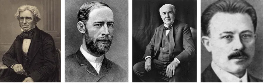
(27) CHAPTER 1. Introduction and Objectives. part, but much lighter, much cheaper, and much easier to produce in serial manufacturing of large quantities. Gold beating in the 18th Dynasty of Ancient Egypt (1543 – 1292 BC) could be considered as the oldest thin film technology documented.[1] Samples from this period have been found to be even below 1 m in thickness. The extraordinary malleability of gold enables it to be rolled and hammered into leafs of just a few microns or even less, which would then be usually applied on top of wood, bronze or copper by means of a small amount of wax or resin. The resulting gilded objects (statues, crowns, coffins) would just appear as if made of pure gold. From Egypt, the craft spread throughout ancient cultures and is still in use nowadays. Thin film deposition by vacuum coating techniques is a much more recent development.[2] The first findings on deposition of materials in a vacuum date from the mid 1800s. They originated rather unintendedly from the study of electrical discharges in vacuum, which was a hot topic for physicists studying electricity and electromagnetism. In 1852 W.R. Groove noticed the deposits formed on a polished silver surface that was the anode of a DC discharge in vacuum, and similar findings were published by M. Faraday in 1854. But it was A. Wright, professor at Yale University, who first recognized that this effect, sputtering as it would be termed a few years later, could be a useful technique to deposit metals on glass to form mirrors and study their properties. Since Wright was not very specific in his experimental description, T. Edison successfully patented the first system for vacuum coating in 1894, after ten years of litigation, although the US Patent Office recognized Wright’s. FIGURE 1.1. Pioneers in vacuum coating. From left to right: Michael Faraday, Heinrich Hertz, Thomas A. Edison, Martin Knudsen.. 18.
(28) CHAPTER 1. Introduction and Objectives. work as prior art.[3] In all these early original works it is not clear whether the processes described by Wright and Edison were really due to sputtering or arc vaporization of material. Surprisingly, thermal evaporation in vacuum was studied later than sputtering and arc vaporization. Works on evaporation of heated material in vacuum were first published by H. Hertz in 1882 but he did not pay any attention to the deposited materials, but only to evaporation rates. Thermal evaporation was also covered by Edison in his 1884 patent application, but apparently it was not applied to any equipment. In 1887 Nahrwold reported the deposition of platinum by sublimation in vacuum and he is credited to be the first scientist to use the technology effectively for the deposition of thin films. Finally, in 1909 Knudsen proposed his well-known “Cosine Law of Distribution” for vapor emerging from a point source. The development of reactor chambers, vacuum pumps, pressure gauges and power sources continued steadily during the first half of the Refth century, but it was with the explosion of microelectronics in silicon integrated circuits in the 1960’s that vacuum coating technologies blossomed and progressed to generate a variety of efficient deposition and etching techniques which soon after expanded to other fields and applications. Many of the techniques developed for thin film deposition and materials processing take place in a special state of matter called plasma. The term plasma derives from Greek’s πλάσμα, meaning “that wat is made”. Faraday was a pioneer in the study of luminous discharges at low gas pressure,[4] back in 1831, which he called glow discharges, but the association of the term “plasma” is generally attributed to Langmuir,[5] who used it in 1929 to describe an ionized gas formed around tungsten filaments in vacuum, when he was investigating on how to expand the lifetime of a lighting bulb for General Electric.(1) The term polymer derives from the ancient Greek word πολύς (polus, meaning "many") and μέρος (meros, meaning "parts"), and refers to a macromolecule whose structure is composed of multiple repeating units. The units composing polymers derive from molecules of low relative molecular mass. Although the term was coined in 1833 by Jöns Berzelius, his definition is completely different from the modern. (1). Langmuir was aware of how an electric field in an ionized gas carries electrons and ions and was reminded of the way that blood plasma carries red and white blood cells[5].. 19.
(29) CHAPTER 1. Introduction and Objectives. definition of polymers as covalently bonded macromolecular structures, which was proposed in 1920 by Hermann Staudinger.[6] Natural polymers can be found among the most important biomolecules: polysaccharides, (such as cellulose), proteins and nucleic acids are all excellent examples of polymers with extraordinary biochemical properties. Synthetic polymers started being developed in the early 1900’s: Bakelite in 1907, PolyVinyl-Chloride (PVC) in 1927, PolyStyrene (PS) in 1930 and Nylon in 1938 where among the first ones to be synthesized. Plasma polymerization can be defined as the formation of polymeric materials under the influence of plasma. Almost simultaneously as the history of sputtering and thermal evaporation started, some studies detected that organic compounds formed solid deposits under the effect of electrical discharges in vacuum. Similarly to sputtering, these coatings were not identified as potentially useful but rather as undesirable by-products; in contrast, it took more than eight decades, in the 1960’s, to recognize this process as a useful means of synthesizing polymers. This was most likely due to the fact that the concepts of polymers and polymerization were not well-developed.[7] Until the mid 1980’s, plasma polymerization was just studied as another method of polymerization, without recognizing the unique properties that could be achieved with these new type of materials such as their higher stability, insolubility and adhesion to any substrates. Although it is possible to use plasma polymerization as a mechanism to obtain materials close to the conventional polymers, it can also be employed to achieve a wide range of properties, from mostly polymer-like to inorganic-like,(2) or even with graded properties, just by controlling different process parameters. Therefore, plasma polymerization should be considered as a method for forming a new type of materials rather than just another method of preparing conventional polymers.. 1.2. FUNDAMENTAL. ASPECTS. OF. PLASMAS. AND. PLASMA. POLYMERIZATION Since a plasma is basically an ionized gas, a complete description of the physical model needs to deal with the properties and interactions of gas molecules in a. (2)When. only an inorganic deposit is sought, plasma deposition is usually referred to as plasma enhanced chemical vapor deposition (PECVD).. 20.
(30) CHAPTER 1. Introduction and Objectives. vacuum reactor and also with the interactions between the electric field and the charged particles and the sequence of processes generated thereafter.. 1.2.1. Gas Physics The interaction among all particles in the gas phase and between these particles and the surfaces in the reactor will greatly influence the deposition rates and the chemical properties and structure of films deposited in plasma polymerization processes. It is therefore important to understand the basic equations governing these phenomena, which are described by the kinetic theory of gases.[1,7]. Number of molecules in a closed reactor In a vacuum reactor, the amount of gas molecules can be related to the pressure, P, and the reactor volume, V, by the ideal gas law, =. ,. (Equation 1.1). where n is the number of moles of gas, R the gas constant, and T the absolute temperature. One mole of gas contains 6.021023 molecules, Avogadro’s number (NA), and at 1 atm it occupies 22.4 liters. Equation 1.1 is simple and yet it has some important implications in all vacuum processes, including plasma polymerization, such as: -. At a given pressure the total number of gas molecules is independent of the molecular weight and the number of atoms per molecule, i.e. the number of Ar, O2, or Si2OC6H18 molecules is the same in a pure gas of each one at the same pressure.. -. In a closed system, if molecules are dissociated the pressure will increase.. -. In a closed system, if molecules are deposited on the surfaces, they will be removed from the gas volume and the pressure will drop.. -. In a closed system, the pressure variation depends on the balance between fragmentation rates and deposition rates.. Molecular velocity For a real gas, Maxwell established the law governing the distribution of molecular velocities and derived the average velocity, ̅ , and the most probable velocity, , as: ̅ = (8. /. ). ⁄. = 1.46 × 10 ( / ). ⁄. cm/s,. (Equation 1.2) 21.
(31) CHAPTER 1. Introduction and Objectives. = (2. / ). ⁄. = 1.29 × 10 ( / ). ⁄. cm/s,. (Equation 1.3). thus, for Ar at 25C the average velocity of molecules will be as high as 39850 cm/s.. Collisions between molecules For collisions between like molecules in a gas, the number of collisions per second, Z, in a volume V (cm3), at pressure P (mbar) and temperature T (K) for a gas sphere of radius d is given by = 1.09 × 10. ∙. /. ∙. ∙. ∙. ∙. ⁄. (Equation 1.4). Mean free path The mean time between collisions is the reciprocal of the amount of collisions per second, and the mean free path, , is the distance traveled by a molecule between successive collisions. If 1 is the mean free path at 1 mbar, the mean free path at a different pressure P (torr) is inversely proportional to pressure: =. ⁄. (Equation 1.5). For oxygen, 1 is 65 m and the mean free path at 0.1 mbar is 0.65 mm.. Collisions of gas molecules with surfaces According to the classical kinetic theory of gas, the number of molecules. striking. a unit surface at a certain pressure P (mbar) and temperature T (K) is given by = 1.62 × 10. ∙ ⁄(. ∙ ). ⁄. molecules /(s·cm2). (Equation 1.6). From equations 1.4 and 1.6 it is easily derived that the number of gas-gas collisions is proportional to P2, whereas the number of gas-surface collisions is proportional to P. In fact, the ratio of total gas-gas collisions (Z·V) to gas-surface collisions ( ·A) in a reactor of volume V and area A is given by = 1.15 × 10. ∙( ⁄ )∙. ∙. ∙. ∙. (Equation 1.7). Equation 1.7. has a practical implication to understand the mechanisms of film growth, that is: larger molecules with larger diameters, higher pressures and larger reactor volumes increase gas-phase reactions with respect to gas-surface ones. 22.
(32) CHAPTER 1. Introduction and Objectives. Monolayer formation time From the flux of collisions. between gas molecules and surfaces the time required. for molecules impinging on a certain surface to form a monolayer of adsorbed molecules, mon , can also be calculated. Assuming a certain sticking coefficient, s, and a certain surface density, dsur, the monolayer formation time is given by =. ⁄( ∙. ). (Equation 1.8). For a surface density of 1015 nucleating sites, a sticking coefficient of 1, a temperature of 298 K and a pressure of 0.1 mbar, one monolayer of a monomer of 162 amu would form on any surface in just 31 s .. Flow rate and pumping rate The flow rate F in a reactor at stable pressure reflects the amount of gas molecules entering and leaving the reactor per unit time. It is expressed as the volume occupied by the flowing molecules at standard temperature and pressure, per unit of time, and it is usually measured in standard cubic centimeters per minute (sccm). One sccm is equivalent to 7.4410-7 moles or 4.481017 molecules entering and leaving the reactor every second. If the vacuum pump in a reactor is closed and the inlet of gas is left open, the pressure in the reactor will increase at a constant rate, from which the input flow rate of gas can be calculated as = 60 · (. ⁄ 0) ∙. (sccm). (Equation 1.9). where VR (cm3) is the volume of the reactor and P0 is the standard pressure; P and P0 need to be expressed in the same units and dP/dt should be the average pressure change per second.. Residence time If the vacuum outlet is opened again the reactor pressure decreases until the pressure is stabilized. At that point, the input flow rate F and pumping throughput of gas Q are equal. The residence time res is the average time spent by a molecule in a reactor before it is pumped out and it is equal to the time needed to renovate all the. 23.
(33) CHAPTER 1. Introduction and Objectives. molecules in the reactor. The residence time can be calculated as the time employed to pump out all the gas molecules from the reactor if the pumping throughput could be kept constant at the same value achieved for the equilibrium pressure. If pressure is expressed in (mbar), reactor volume in (liters), temperature in (K) and flow rate in (sccm), the residence time is given by = 1.62 × 10 ∙ ( ∙ )⁄( ∙ ) (s). (Equation 1.10). For a flow rate of 1 sccm in a 100 L reactor at a pressure of 0.1 mbar and 25C, the residence time will be 543 s. In a practical approach, the residence time is usually controlled by changing the pumping speed and the flow rate simultaneously and maintaining the pressure. According to Equation 1.10, larger reactors, higher pressures and lower flow rates will favor long residence times, which will increase the amount of interactions of molecules with other molecules, with charged and energetic species and with the surfaces inside the reactor. This has a decisive effect on plasma polymerization.. Flow regimes For systems with a net flow of gas, the mean free path defines the boundaries between different flow regimes which are characterized by an individual or a collective behavior, depending on the amount of collisions between molecules. Criteria for distinguishing between the different flow regimes are based on the magnitude of the Knudsen number, Kn, which is defined as the ratio of the mean free path to a characteristic dimension of the system (chamber diameter or length). At low gas pressures, where Kn > 1, free molecular flow regime occurs, which is very accurately described by the kinetic theory of gas. The main free path in this regime is large when compared to the characteristic dimensions of the reactor, and molecule-surface interactions predominate. At higher pressures, where Kn > 0.01, the amount of molecule-molecule collisions in the gas phase increases, the mean free path diminishes and the viscous flow regime is established. The theory of fluid mechanics offers the best picture to explain how molecules flow in these conditions. At low gas velocities the flow is mainly laminar with layered, parallel gas flow lines and with laminar flow velocity close to zero at the. 24.
(34) CHAPTER 1. Introduction and Objectives. walls of the reactor and higher towards the central axis. For higher flow velocities, the layers cease to be parallel and can create swirls, especially around obstacles in their way. This is known as the turbulent flow. It is worth noting that the boundaries between these regimes are diffuse and in the middle, where 1>Kn>0.01, the flow is neither completely molecular nor viscous. It is also to be noted that some parts of the reactor may be at a different regime, e.g. close to the inlet of processing gas and near the outlet leading to the vacuum pumps.. FIGURE 1.2. Boundaries for the different flow regimes. Plasma Polymerization takes place in a transient regime which is neither molecular nor completely viscous.. Plasma polymerization processes take place usually somewhere in between the molecular and the laminar viscous regimes as shown in Figure 1.2.. 1.2.2. Plasma Physics Plasmas are naturally present in the Universe: the sun and the rest of the stars consist entirely of plasma; the earth’s ionosphere, the space between galaxies and, closer to us, lightning, polar auroras and most fires(3) are also good examples of (3). There is some debate about whether fire can be considered a plasma or not. Von Engel proposed a simple method to settle down the question: a flame is placed between two parallel plates and an electric field is applied. If the flame is deviated towards the cathode, it can be considered as a plasma.. 25.
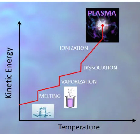
(35) CHAPTER 1. Introduction and Objectives. natural plasmas. Plasma can also be artificially created in the laboratory by combustion, electric discharge, controlled nuclear reactions or other means. Even in some consumer products we may find plasmas, such as in the almost extinct plasma TV sets, in common fluorescent tubes or in the old-fashioned neon tubes.. FIGURE 1.3. A plasma state can be achieved by increasing the temperature of a gas beyond several thousand degrees. It is considered as “the fourth state of matter” above less energetic states of solid, liquid and gas.. The simplest definition of plasma would be an ionized gas. A more complete definition would include also its complex composition: electrons, ions (both positive and negative), neutral molecules and atoms either in the ground or excited states and photons. In addition, plasmas posses important properties such as quasineutrality, electrical conductivity and a collective fluid behavior of electrons. Plasma is also commonly referred to as “the fourth state of matter” (4). Such a reference originates from the comparison with the remaining three physical states: solids, liquids and gases. The main difference between these states is the kinetic energy of the atoms and molecules: the higher the energy the more freely can molecules depart from their neighbors. Kinetic energy of neutral molecules is increased by different mechanisms of energy absorption and it is macroscopically perceived as an increase in temperature. When the energy of molecules is further increased, spontaneous. (4)The. expression “the fourth state of matter” is attributed to Crookes, who first used it in a pioneer paper in Phyllosophical Transactions, vol. 1, p.135 (1879). 26.
(36) CHAPTER 1. Introduction and Objectives. dissociation of molecular fragments or atoms will occur. At many thousand degrees centigrade, the collisions of these fast particles would produce ionization of the atoms. The onset of ionization is the door to the plasma state (Figure 1.3). As a reference, the ionization energies for oxygen and nitrogen are in the range of 13-15 eVs. The energy required to produce the ionization of an atom can be provided by fast particle (high T) collision or by photon absorption. A charged particle with kinetic energy of 1 eV has an equivalent temperature of 11600 K, which is given by T= E / kB, where kB is Boltzmann’s constant.. Plasma species and degree of ionization As mentioned, all plasmas are composed of charged particles (electrons, ions) and neutral ones, with respective densities ne, ni and n0. The plasma is electrically neutral in average and therefore ne = ni << no . The degree of ionization, fi, represents the fraction of ionized atoms or molecules with respect to the total amount, and it is also an important characteristic of plasma. The degre of ionization is simply defined as =. ⁄(. +. ). (Equation 1.11). Plasmas for material processing and thin film deposition have low degrees of ionization which may range from 10 -7 to 10-2. The density of charged particles can be calculated from the ideal gas law (Eq. 1.1): at 0.1 mbar, n01015 cm-3, hence electron density for these plasmas will be in the range 108 to 1013 cm-3.. Electron temperature, ion temperature and plasma temperature Plasmas at low pressures do not achieve complete thermalization of all particles, which means that the temperature of electrons, Te, ions, Ti, and neutrals, Tn, can be extremely different. This non-equilibrium situation is also possible because the mechanisms by which electrons, ions and neutrals gain and dissipate energy can be different. For example in the presence of an electric field, both electrons and ions can gain energy from the electric field, whereas neutrals cannot. In addition, electrons can gain much higher energies from the electric fields because they do not lose significant fractions in inelastic collisions, whereas ions and neutrals do.. 27.
(37) CHAPTER 1. Introduction and Objectives. Depending on the difference in the energy of electrons, ions and neutrals, plasmas can be further classified between thermal plasmas, if Te = Ti = Tn , and non-thermal or ‘cold’ plasmas, if Te >> Ti >> Tn. Most artificial plasmas are non-thermal plasmas and all glow discharges employed for plasma processing of materials have average electronic temperatures between 104–105 K, ion temperatures between 300 – 1000 K and neutral temperatures at room temperature or slightly higher. Figure 1.4. illustrates the electron density and electron temperature for different natural and artificial plasmas.. FIGURE 1.4. Density of charged particles (electrons) and equivalent temperature for different natural and artificial plasmas.. Energy transfer by particle collision Theoretically, energy transfer by particle collision can occur in atom-atom, electron-atom, electron-ion, electron-electron, ion-ion and ion-atom. When the relative energy of the colliding particles is large, an inelastic collision occurs and part. 28.
(38) CHAPTER 1. Introduction and Objectives. or all of the kinetic energy will be absorbed into potential energy of electrons in the target atom, except for ion-ion and electron-electron collisions in which only elastic collisions are possible due to high repulsive forces. For elastic collisions between an electron and a slow neutral, and an ion and a slow neutral, by conservation of energy and momentum, it can be shown that the fractions of energy Qe and Qi lost by the electron and the ion respectively depend on their relative masses with respect to the neutral and are given by[8] Q = 4 ∙ Q = 2− 2. / /(. (Equation 1.12) +. ). (Equation 1.13). where me and mn are the mass of the electron and the neutral atom or molecule respectively. According to Equations 1. 11-12, when electrons and ions collide elastically with slow moving neutrals, electrons do not lose a significant amount of energy due to the extreme difference in mass between an electron and an atom or molecule, and therefore electrons will continue to gain energy until they suffer an inelastic collision. On the contrary, ions and neutrals can lose a significant fraction of their kinetic energy with each collision with another neutral or ion, either in elastic and inelastic collisions. For inelastic collisions, conservation of energy requires that the energy before and after the collision be the same. Thus, for particles of mass m1 and m2 and initial velocities v1 and v2: +. =. ′ +. ′ +Φ. (Equation 1.14). where is the energy absorbed by the collision. If is higher than the ionization energy, collision will lead directly to ionization; if is less than the ionization energy but more than the excitation energy, the atom will be activated and an electron in the atom will be promoted to a higher energy level where it will stay for a short time (10-8 to 10-9 s), after which it will decay to the ground state and emit the excess energy as a photon. If metastables exist (excited states with longer decay times) ionization could be possible even if is less than the ionization threshold.. 29.
(39) CHAPTER 1. Introduction and Objectives. Types of collisions In general, electron-neutral collisions leading to dissociation, excitation and ionization are by far the most frequent ones but other types of collisions can lead to additional reactions. These have been clearly summarized by Ohring[1] as follows: Electron collisions 1. Ionization. +. →. 2. Excitation. +. →. 3. Dissociation. +. →. 4. Dissociative ionization. +. →. 5. Dissociative attachment. +. →. 6. Recombination. +. →. + 2. +. →. + 2. +. +. → (. )∗ +. ∗ ∗. +. + +. ∗. + + 2 + 2. Atom – molecule – ion collisions 7.. Symmetrical charge transfer. +. →. +. 8.. Asymmetric charge transfer. +. →. +. 9.. Metastable-neutral (Penning ionization). ∗. +. 10. Metastable – metastable ionization. ∗. +. → ∗. →. + +. + +. Energy transfer by photon absorption Photons are capable to produce direct photodissociation, photoexcitation and photoionization provided that their energy is higher than the respective thresholds for dissociation, excitation and ionization. Taking into account that the energy of a photon of wavelength is given by hc/, where h and c are Planck’s constant and the velocity of light respectively, the wavelength of photons capable of photoionization is written as follows: (. ) ≤ 1239.8⁄. where is the ionization energy in eV.. 30. (Equation 1.15).
Figure


+7
![FIGURE 1.5. Paschen curves for commonly used simple gases. Adapted from [12].](https://thumb-us.123doks.com/thumbv2/123dok_es/5315438.98545/41.595.89.524.497.678/figure-paschen-curves-commonly-used-simple-gases-adapted.webp)
![FIGURE 1.6. Luminous and dark regions in a DC Glow Discharge. Adapted from [9].](https://thumb-us.123doks.com/thumbv2/123dok_es/5315438.98545/42.595.109.495.349.566/figure-luminous-dark-regions-dc-glow-discharge-adapted.webp)
![FIGURE 1.7. Luminous and dark regions in a DC Glow Discharge. Adapted from [10].](https://thumb-us.123doks.com/thumbv2/123dok_es/5315438.98545/44.595.151.452.365.521/figure-luminous-dark-regions-dc-glow-discharge-adapted.webp)
![FIGURE 1.8. Luminous and dark regions in a DC Glow Discharge. Adapted from [10].](https://thumb-us.123doks.com/thumbv2/123dok_es/5315438.98545/45.595.156.422.537.700/figure-luminous-dark-regions-dc-glow-discharge-adapted.webp)
Documento similar
In this respect, a comparison with The Shadow of the Glen is very useful, since the text finished by Synge in 1904 can be considered a complex development of the opposition
The Dwellers in the Garden of Allah 109... The Dwellers in the Garden of Allah
Since such powers frequently exist outside the institutional framework, and/or exercise their influence through channels exempt (or simply out of reach) from any political
The synthesis and analysis of these properties were then featured by (i) the composition, geometry, and electronic and mag- netic structure of the exposed surfaces at the
Of special concern for this work are outbreaks formed by the benthic dinoflagellate Ostreopsis (Schmidt), including several species producers of palytoxin (PLTX)-like compounds,
The small ubiquitin-like modifier-1 (SUMO-1) consensus sequence mediates Ubc9 binding and is essential for SUMO-1 modification J Biol Chem 276, 21664-69. Transcription factor Sp3
In the previous sections we have shown how astronomical alignments and solar hierophanies – with a common interest in the solstices − were substantiated in the
While Russian nostalgia for the late-socialism of the Brezhnev era began only after the clear-cut rupture of 1991, nostalgia for the 1970s seems to have emerged in Algeria
