Origin of equilibrium methods applied to the structural calculation of long cylindrical shells
21
0
0
Texto completo
(2) Origin of equilibrium methods applied to the structural calculation of long cylindrical shells. Figure 1. Long cylindrical shells on the roof, under construction, in the Dywidag Hall at the Gesolei Düsseldorf. Fr. Dischinger and U. Finsteerwalder. 1926. “Die Dywidag-Halle auf der Gesolei”. Der Bauingenieur 7, figure 3, pp. 929, 930. in Germany in the 1930s, as a result of the work done by the engineers Fr. Dischinger 2 3 4 5 and U. Finsterwalder 6 7 8, and subsequently the Norwegian A. Aas Jakobsen 9 10 11 12 13As a result of its application, it was thought to be possible to precisely determine the state of stress at each point in the shell, by solving eighth-order differential equations of great mathematical complexity. The solution to these equations determined the stresses and moments at all points in the shell, which was made of a homogeneous, isotropic and ideal material, as stipulated by Hooke’s law. However, in practice, it also became necessary to introduce a number of hypotheses, important and legitimate, provided that this did not contradict the real results. The result of all this was that the accuracy of the results provided by the theory of elasticity in the structural calculation of shells could be not guaranteed, except in cases where the accuracy of the hypotheses had been established beforehand. All these factors, coupled with the fact that reinforced concrete did not comply with the fundamental assumptions of the theory of elasticity, as it was not an ideal, homogeneous and isotropic material, led to the appearance of major inconsistencies between the results of the calculation and what subsequently occurred in reality. In the theory of elasticity, based on the elastic behaviour of material, both the equilibrium between the internal and external forces and the compatibility of deformations had to be satisfied. In addition, solving the mathematical problem provided by the equilibrium equations became an indeterminate when the shell was attached to other deformable structural items, such as edge beams, other similar and contiguous shells, etc. In these cases, it was necessary to supplement the equilibrium equations provided by membrane theory with other equations generally derived from working theorems which considerably increased the complexity of the mathematical development.. 54.
(3) Mónica Martínez Martínez. Consequently, some obvious and significant insurmountable inconsistencies between the results obtained from the elastic calculation and the results under real conditions and in tests began to appear. A theoretical framework more appropriate to the one provided by elastic theory for the structural calculation of these types of structure was the study of the conditions in which the collapse of the structure occurred; or in other words, limit analysis. Although the ‘real’ state of the structure could not be determined, its strength could be calculated accurately; it was also very insensitive to supposed shortcomings in the manufacture or execution, and to small variations in the conditions of the surroundings. As a result, since 1936, a new interest began in the analysis of these structural types using plastic methods, as will be discussed in this document.. The Origin of Plasticity Studies – Their Application to Reinforced Concrete. Although the assumptions established by the theory of elasticity seemed reasonable, common sense suggested that a minor defect or imperfection in the shell, or at least an unpredictable one, would not really affect its strength. There also came a point at which the contradictions between the constructive reality of these types of structure and the results of the analytical calculation were unacceptable. As a result, the search began for new, simpler and more effective calculation methods, which would provide a more accurate response to the real characteristics of the structural material used: reinforced concrete. G.v. Kazinczy The Hungarian Gábor Kazinczy (1888-1964) was one of the first engineers who based the calculation of the plasticity of structures not only on theory, but also on empirical data obtained in tests. The plastic theory, unlike the elastic theory, has to do with the distribution of stresses in a structure, after in some points of this one the effort of creep has been reached. Those parts of a structure that have reached the creep effort cannot resist additional efforts; rather, those parts will flow the amount necessary to allow the additional load or stresses to be transferred to other parts of the structure where the stresses are below the creep effort and these are capable of absorbing said additional stresses. In 1914, after examining the results of the experiment carried out on a clamped-end steel beam, he was able to demonstrate that the calculation of elastic stresses was not relevant when predicting the real strength of a structure14; if it was constructed using a ductile material, it was not dependent on the appearance of the threshold for elastic stress at a point on it, but instead on the unacceptable increase in the deformations in it, due to the action of the loads (Figure 2). Later, in 1933, after experimenting with continuous reinforced concrete beams, he proposed the concept of the redistribution of simple bending moments, based on the plastic behaviour of both steel and concrete15. In the state in which the collapse of a structure occurs, the distribution of moments, or stresses, need not meet comply with the stipulations of the theory of elasticity. In fact, when breakage takes place, the moments are distributed with the same value in the three critical sections of the beam. By varying the closing line of the beam’s isostatic diagram, it is possible to distribute the moments as required, provided that the reinforcements are arranged according to this choice. Two significant events occurred related to the study of plastic methods three years later, in 1936: the important papers on plasticity presented at the Second Congress of the IABSE (6), in Berlin, and the theorems of plasticity announced by the Russian A. A. Gvozdev.. 55.
(4) Origin of equilibrium methods applied to the structural calculation of long cylindrical shells. Figure 2. Kazinczy G.v. 1914. “Experiments with Clamped end Beams.” Betonszemle, no. 4, part III. Congress of the IABSE in Berlin The second congress of the International Association for Bridge and Structural Engineering (IABSE) was held in Berlin in 1936. In spite of the widespread conformist thought, within the theoretical field of structures regarding the theory of elasticity, the IABSE Congress held in Berlin was a milestone in the. 56.
(5) Mónica Martínez Martínez. progress of research on plasticity in general. Eight papers on plastic theory were presented in the preliminary report of a congress for the first time: A. Freudenthal, Dr.Sc., “General Theory of Plasticity, Fields of Equal Yield Lines”. J. Fritsche, Dr.Sc., “Fundamental Principles of the Theory of Plasticity”. F. Rinagl, Dr.Sc., “Yield Limits and Characteristic Deflection Lines”. E. Melan, Dr.Sc., “Theory of Statically Indeterminate Systems”16. E. Kohl, Dr.Sc., “Carrying Capacity of Trussed Steel Work”. R. Lévi, Dr.Sc., “The Safety of structures”. H. Maier-Leibnitz, Dr.Sc., “Test Results, their Interpretation and Application”17. F. Bleich, Dr.Sc., “Calculation of Statically Indeterminate Systems based on the Theory of Plasticity”. Perhaps the most interesting is the paper presented by the engineer Heinz Maier-Leibnitz (1911-2000), in which he presents the results obtained from experiments carried out on continuous beams on three supports. The beams were subjected to the action of an external load, while their central support was moved upwards or downwards (figure 3).. Figure 3. Maier-Leibnitz, H. 1936. “Test Results, Their Interpretation and Application”. IABSE Congress, Preliminary Report, Vol 2, p. 101. Berlin.. 57.
(6) Origin of equilibrium methods applied to the structural calculation of long cylindrical shells. Maier-Leibnitz found that when he performed the calculation according to the theory of elasticity, the values of the possible loads depended on the location of the central support. However, when he performed the test, the value of the collapse load was not affected by the different levels of the supports. The collapse only occurred when a sufficient number of joints were formed to constitute a mechanism, regardless of the initial defects that the structure may have had. The strength of the structure therefore ultimately depended solely on its plastic behaviour, and not on any possible imperfection that could arise during construction, such as a poor levelling in its supports. The second paper of interest was given by the engineer F. Bleich. He defined the phenomenon of settling, based on the practical application of the plastic equilibrium method for the calculation of statically indeterminate structures subject to alternative load conditions. According to plastic equilibrium method, any arbitrary equilibrium situation that satisfies the plasticization condition would provide an estimate of the collapse load less than or equal to the correct one. This means that finding a state that satisfies the equilibrium conditions and plasticizing leaves us on the side of safety. Bleich explains how there are an infinite number of solutions to equilibrium equations; one of these is Navier’s elastic solution. However, it is not the only one since there are also other equilibrium solutions, which are easy to calculate, such as the state of collapse which constitutes the starting point for plastic calculations. In several communications at the congress, and particularly those by H. Maier-Leibnitz and E. Melan, reference was made to the work of the American mathematician William Prager (1903-1980). In 1941, Prager founded the Department of Applied Mathematics at Brown University where among other things, he developed the mathematical principles of the theory of plasticity18. Prager made progress in these studies based on the knowledge that had been accumulated in Central Europe in the 1930s, as a result of the work done by Kazinczy19, and the communications on plasticity that were presented at the Berlin Congress of the IABSE. A. A. Gvozdev. Application of the theory of plasticity to reinforced concrete. Despite the breakthroughs made in the study of plastic methods at the IABSE Congress in Berlin in 1936, there was still a pressing need to establish the fundamental theorems that defined it. Accordingly, new areas of research began to take shape, despite the instability at the time due to the proximity of the Second World War. In 1936, also at the same time as the IABSE Congress in Berlin, the Russian A.A Gvozdev presented a communication with a paper on plasticity20; it specifically addressed how to determine the value of the collapse load in statically indeterminate reinforced concrete systems. Gvozdev lists the three conditions that must apply in the state of collapse of a structure: the conditions of balance, yield and mechanism. The problem therefore lies in finding the value of the collapse load for which the three conditions are met simultaneously; and this enables the fundamental theorems of the theory of plasticity to be deduced: • • •. Theorem of Uniqueness. The collapse load has a unique, defined and calculable value. Upper Bound Theorem. The value of the collapse load must be equal to or less than that produced at the moment of collapse. Lower Bound Theorem. The collapse of a structure will not occur if each successive charge status which happens structure is possible to find a statically admissible state of equilibrium. This third theorem can therefore obtain a lower limit value of the collapse load.. These three conditions make no reference to the initial state of the structure, or to possible stresses due to changes in temperature, settling, etc. W. Prager heard about the work Gvozdev had done in 1948, and in 1952, he published his demonstration of the fundamental theorems of the theory of plasticity.. 58.
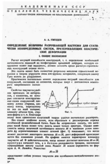
(7) Mónica Martínez Martínez. Figure 4. A. A. Gvozdev. 1932. “On the analysis of thin-walled cylindrical shells”, p. 44.. Despite its extraordinary significance, the work done by Gvozdev did not arouse any great interest at that time; in fact, it was not published until 1938, in Russian, in the Proceedings of the Academy of Sciences of Moscow (figure 4) and it was subsequently translated into English in 1960 with the title “The determination of the value of the collapse load for statically indeterminate systems undergoing plastic deformation”. The path towards the development of new calculation techniques within the plastic method began in 1950, with the demonstration of the Fundamental Theorems of the theory of plasticity and the consolidation of the theory. Plastic theory was initially developed for steel structures, although the research by the Russian A.A. Gvozdev focused on calculating the limit loads in reinforced concrete structures. Indeed, the first text that includes knowledge about plastic theory for the calculation of steel frames to rigorous critical standards, The Steel skeleton. Vol 2: Plastic behavior and design (J. Baker, M.R. Horne and J. Heyman), was not published until 1956 21. Plastic calculation methods were subsequently also applied to reinforced concrete structures, and to any other structure, provided that they had a ductile behaviour with no problems of instability.. 59.
(8) Origin of equilibrium methods applied to the structural calculation of long cylindrical shells. While the elastic analysis of a structure is based on the concept of admissible stress22, the new concept of limit analysis is therefore the concept of a limit load; i.e. the load at which the state of collapse of the structure occurs, establishing the safety thereof. The mathematical theory of plasticity is based on calculating a structure’s collapse load, using the three Fundamental Theorems of limit analysis, and it can be applied to any material or structure with plastic properties23. This concept basically requires an absence of problems of stability or major deformations, so that the elastic stresses can be ignored; meanwhile, the adequate ductility of the material ensures the correct redistribution of the stresses, without damaging or breaking the structure.. K.W. Johansen and the Application of Limit Analysis to the Structural Calculation of Long Cylindrical Roof Shells In addition to the above, a further development took place in Denmark, related to the studies carried out by the Danish engineers K.W. Johansen and H. Lundgren on the application of the limit analysis to the. Figure 5. General Broadcasting Corporation Building, Copenhagen 1938. Johansen, K.W. (1944). “Skalkonstruktion paa Radiohuset. Beregning og forsog”. Bygningsstatiske Meddelelser, no. 15, p. 1.. 60.
(9) Mónica Martínez Martínez. structural calculation of long cylindrical shell shells. Prior to the publication of the book Cylindrical Shell by H. Lundgren in 1949 24, the literature about the structural analysis of long cylindrical shells contained very few studies of the problem apart from membrane theory or above all, the theory of elasticity. The contributions by the engineer Winstrup Knud Johansen to structural analysis and the calculation of long cylindrical shells were decisive in this respect, since they mark the beginning of the application of limit analysis to these types of structure with a plastic approach to equilibrium. In 1944, Johansen published a very important article, in which he performed a structural analysis of a long cylindrical shell in a real roof25. The calculation was based solely on the equilibrium equation approach, thereby enabling a simple and reliable calculation of these structural types (Figure 5). Other engineers such as the Hungarian G. Kazinczy26 and the Dane H. Lundgren subsequently continued with this type of study; it was the latter, as well as K.W. Johansen, who formulated a practical, clear and simple theory for application based on the equilibrium approach in the late 1940s. The shell forming the roof of the General Broadcasting Corporation building, used by the film industry in Copenhagen, built in 1938. The structure covers an area 16 m wide and 36 m long; it is divided in two spaces, one of 24 m and the other of 12, by means of a partition wall arranged across it. On the north. Figure 6. Geometrical definition of the cross-section of the long cylindrical shell of the General Broadcasting Corporation Building, Copenhagen 1938. Statsradiofonien. (1946). “Radiohuset: den Danske Statsradiofonis nybygning i Kobenhavn”. Akademisk Arkitektforening, p.137.. 61.
(10) Origin of equilibrium methods applied to the structural calculation of long cylindrical shells. side of the building, the shell is supported by pillars spaced 3.2 m apart; while on the south side of the building there is no support. The shell also is bounded at both ends by two transverse walls. The crosssection of the roof, which has a thickness of 12 cm, is roughly cylindrical but it has a ventilation channel inside. The cross-section of the long cylindrical shell (Fig. 6 and 8) is established by a circular arc ABD, with a radius of 9.22 m. At point B on the arc, it tangentially touches another arc BC, with a radius of 14 m. In turn, a vertical straight section CD starts at point C, thus closing its cross-section together with a concrete ogee as a cantilever roof. Analysis method. The method used by Johansen in his analysis of the shell consists of comparing the shell’s behaviour to that of a reinforced concrete beam (figure 7). Since there are an infinite number of solutions to equilibrium equations, in addition to the Navier’s elastic solution, Johansen attempts to find an equilibrium solution that is easy to calculate, such as the state of collapse.. Figure 7. Diagram of similarity between a reinforced concrete beam and a long cylindrical shell. Lundgren, H. 1949. Cylindrical Shells. Volume I Cylindrical Roofs. The Danish Technical Press. The Institution of Danish Civil Engineers. Chapter 10, section 106, figure 106.1, p. 55.. The hypotheses formulated prior to the calculation are as follows: 1. Model the cross-section of the shell, dividing it into two parts due to its uneven structural behaviour. Due to its stiffness, Johansen relates the structural behaviour of the part of the shell considered closed and defined by points B, C and D to that of a concrete beam. Meanwhile, due to its low stiffness, he considers the part defined by points A and B as similar to a membrane, i.e. where stresses act solely on its plane. As for the value of the reactions, on the supports of the shell’s edge A, it will comply with the following expression: S = Prcosa. [1]. This expression being similar to the one referring to the value of normal union forces in the direction tangent to the curve: Nf = Prcosf, Where P is the value of the external forces acting on the shell and Nf is the value of the normal force in the direction tangent to the curve: Nf = Prr Pr is the value of the normal load: Pr = Pcosf and S is the value of reactions in the direction tangent to the curve.. 62.
(11) Mónica Martínez Martínez. In 1928, Dischinger and Finsterwalder wrote on this subject; the components of the load P acting in a distributed manner along the cylindrical shell in the direction of the three axes. 2. The second hypothesis refers to the rupture lines, or limits. Johansen says that the contribution of the concrete is not solely in terms of its tensile strength; while the acceptable stress in the iron reinforcements was that of the creep within a safety coefficient. In other words, he introduces the real and fundamental characteristics of the structural materials used, in contrast to the provisions of elastic theory. 3. Finally, Johansen says that in statically indeterminate conditions, the moments will be distributed in accordance with the reinforcement made, i.e. in accordance with the theory of plasticity. These assumptions, set out by Johansen and applied to the structural calculation of a long cylindrical roofing shell, form the basis for limit analysis with its equilibrium approach. Having established the hypotheses, the structural analysis method used is based on the long cylindrical shell’s behaviour being similar to that of a reinforced concrete beam (Fig. 7), which has the following calculation process. Longitudinal calculation of the shell. First, he obtains the value of the external forces acting on the shell. These actions consist of the permanent load, with a value of 340kg/m2, and the variable load of 100kg/m2. The resulting value is therefore L = 9.80t/m, acting at a distance of 1,06 m from point B (Fig. 8). Likewise, the reactions in the pillars, located on the north side of the building and in the direction tangential to the curve, will have a value of S = 2.70t/m [1] for an angle a = 48.62º at the start of the shell at point A, and will have horizontal component, SI = 2.00t/m and vertical component, Sv = 1.80t/m Combining the horizontal component, in a polygon of forces (top right in Fig. 8), with the resultant of the external forces L, gives an oblique resultant with a value of P = 7.40t/m. While the part of the cylindrical shell defined by points A and B rests on pillars, the other part of the shell, defined by points B, C and D, has a free end. This part of the roof consists of two spaces; each one is defined by the transverse end wall and the partition wall located in the middle of the building. As a result of these characteristics, Johansen proposes that the part of the shell defined by points B, C and D should be calculated as if it was a continuous concrete beam with two spaces; but with a plastic approach to the equilibrium, respecting the characteristics of the structural material used. It is here where the simplicity and validity of the method proposed truly lies. The moment of abutment is obtained directly with a value of: 3 t 2 Memo = — 327.40 – m (24 m) = 400 tm. [2]. This moment of abutment it would be greater than the real one because in fact the shear stress has a value greater than the theoretical case of the beam. Johansen estimates the value of this moment of abutment, according to the theory of elasticity, at 370tm; while the largest positive moment will be M = 365tm.. 63.
(12) Origin of equilibrium methods applied to the structural calculation of long cylindrical shells. Figure 8. Representation of external loads and internal forces in the cross-section of the cylindrical shell for the positive moment and polygons of forces and obtaining the neutral axis in the state of balance in the cross-section of the shell. Self-made figure based on: Johansen, K.W. (1944). Skalkonstruktion paa Radiohuset. Beregning og forsog. Bygningsstatiske Meddelelser, 15, p. 4. After obtaining the moments, Johansen places the neutral axis in the cross-section of the shell in order to obtain the normal stress and compressive forces. As the cross-section of the shell is unable to withstand torques, which is common in open sections, Johansen suggests placing the neutral axis based on a single assumption: that the resultant of the tangential forces has an equal magnitude and an opposite direction to that resulting from the shear stress Q; which in turn must be equal to the value obtained for the oblique resultant of the loads (Fig. 8). In other words, starting from a condition of equilibrium of forces, Johansen establishes the location of the neutral line, obtaining a solution to the structural problem as a result; but it is not the only one, because another positioning of the neutral line would obtain another state of equilibrium that would address other assumptions. The true location of the neutral axis (line n-n’ in Fig. 8) is determined empirically, i.e. after performing various tests only considering the equilibrium of tensile and compressive forces. Once the neutral axis has been located, it is easy to determine the reinforcement area required, and the concrete stress and shear stress. The point furthest from the neutral axis in the point designated B’, and as such that point will have the greatest compressive stress. Meanwhile, iron rods are placed around the shell, at the centres of mass TA and TD. As a result, the neutral axis is positioned at a distance of 0.80 m from the centre of mass of the tensioned axis TD, and 0.43 m from point B’, where the most compressed axis in the shell is located (Fig. 8).. 64.
(13) Mónica Martínez Martínez. For these distances and the rod stress, provided by Johansen in this article with a value of 1200kg/cm2 at the point TD, the maximum compressive stress in the concrete, s is determined as follows: s=. 1200kg/cm2 0.43m = 43kg/cm2 0.80m 15. Having obtained the value of the maximum compressive stress for concrete, Johansen then calculates the module, the direction and the point of application of the resultant of the compressive stresses N, — corresponding to a value of N = 193t; indicating that the bending plane must contain the force vector P , meaning that the moment must be perpendicular to this plane. The torque, constituted by the result of the — tensile and compression forces, must therefore be contained on the same plane that contains the force P . On this basis, the point of application is obtained by the intersection of two lines. One is the line ______ connecting the resultants of the tractions, i.e. the line TA – TB; while the second is a line parallel to the direction of Q, which passes through the point B’, i.e. the line resulting from the compressions. The distance between points B’ and T (Fig. 8) determines the lever arm between the torque, forming a distance of . The value of the positive moment, M, will therefore be: M = 193t.1.90m = 367tm. [3]. Knowing the tension relative to the steel used, the necessary area of traction reinforcement, A, will be determined by the expression: A=N – s. [4]. where, N is the resultant of the compressive stresses and s is the value of the maximum compressive stress in the concrete. In short, the procedure followed by Johansen related to the longitudinal calculation of the long cylindrical shell, based on successive results obtained by the equilibrium of forces is as follows: 1. Obtaining the value of the external loads. 2. Calculation of the positive and negative bending moments. 3. Obtaining the location of the neutral axis neutral axis in the cross-section of the shell by the equilibrium of forces. 4. Calculation of the maximum compressive stress of the concrete. 5. Obtaining the values for the normal forces of tension and compression. 6. Calculation of the longitudinal reinforcements in the shell. 2. Transverse calculation of the shell. To do this, Johansen uses the beam theory, where the normal forces in the direction of the shell, Nx, are concentrated in a single generatrix, called the beam, and applied at the centre of mass in the area concerned; while the tangential forces, Nxj, in the cross-section of the shell remain constant within each interval between two beams27. In the beam method, for a cylindrical cross-section, the resultant of the shear stresses H is placed on a line parallel to the bowstring at a distance h = 4/3f; measured from the bowstring where f is its height measured from the bowstring. Meanwhile, the resultant of the shear forces H in this range would have a value of KH, where K is the value of the bowstring of the arc.. 65.
(14) Origin of equilibrium methods applied to the structural calculation of long cylindrical shells. The beam method therefore determines the location of each beam, the value of the normal forces in each one, and the tangential forces between the beams. ⌢ ⌢ On this basis, Johansen divides the cross-section of the shell analysed into three different arcs: AB’, B’D ⌢ and C’CD; calling the tangential forces in each of the three sections: HA, HC, HD, meaning the resultant of each one would be (Fig. 8): 9.3HA, 2.5HC and 3.0HD The value of each one is obtained by decomposing the shear force Q, or the shear stress (the polygon of forces located in the upper left of Fig. 8), according to the three resultants of the tangential forces: HA =. 0.77Q 0.64Q 0.59Q = 0.083Q, HC = = 0.256Q, HD = = 0.197Q 0.93 2.5 3.0. Since the lever arm is 1.90m, then: H = HA + HC + HD =. Q’ 1.90m. [5]. Similarly, by making cuts only through Ta and Td, we obtain: HA =. Q T · A 1.90 T. HC + HD=. = 0.097Q. Q T · D = 0.430Q 1.90 T. With the ratio of these values to those previously determined in the polygon of forces we obtain: HC = 0.243Q and HD = 0.187Q Johansen thereby guarantees the real location of the neutral axis, and as has been demonstrated, he does so by means of the equilibrium of forces. The process would be the same for the cross-sections of the shell for the location of the corresponding negative moment. As in the case of the cross-section of the shell belonging to the positive moments, the normal compressive forces located in this case at both points A and D, with a lever arm of 1.80m would be calculated as follows: T=. 370tm = 205t = N = NA + ND 1.80m. [6]. Thereby obtaining a stress for the concrete of 66kg/cm2. ⌢ ⌢ ⌢ In this case, Johansen divides the cross-section of the shell into three parts: A T, T D and TC D, positioning the tangential forces belonging to each of these three sections and the magnitude of their resultants, after decomposing the force Q into a funicular polygon.. 66.
(15) Mónica Martínez Martínez. Calculation of transverse moments: By sectioning an element of the shell (Fig. 9), of length dx in the direction of the generatrix of the shell and width ds, orthogonal to the previous one, we see how the resultant of the shear stresses H act upon it, due to the action of the external loads P.. Figure 9. Representation of external loads and internal forces in the cross-section of the cylindrical shell. Self-made figure.. As the resultant of the shear stresses, H, it is proportional to the shear force, or shear Q, meaning that the shear stresses, t, are also proportional to the external loads, i.e.: – ∂Q = P = 7.4t/m, ∂x. [7]. – where P is the oblique resultant of the external forces. Johansen obtains the various values for the shear stresses t in each section according to the values previously calculated for the tangential forces (Fig. 8): ⌢ For the section A B: tA = 0.097 · 7.4 = 0.72t/m2 ⌢ For the section B’’’C: tC = 0.243 · 7.4 = 1.80t/m2 ⌢ For the section B’’’D: tD = 0.187 · 7.4 = 1.38t/m2. 67.
(16) Origin of equilibrium methods applied to the structural calculation of long cylindrical shells. As t does not vary along the length of the shell, i.e. in direction x, the tangential moments due to t will also be constant along that length. The transverse moments that Johansen analyses are those due to (Fig. 10): - Transverse moments due to shear forces (Fig. 10a). - Transverse moments due to the external load P (fig 10b). - Transverse moments due to reactions in the pillars (Fig 10c).. Figure 10. Obtaining tangential moments. Self-made figure based on: Johansen, K.W. (1944). Skalkonstruktion paa Radiohuset. Beregning og forsog. Bygningsstatiske Meddelelser, no. 15, p. 8.. The following expressions are obtained for all of these: Moment due to the tangential force t, (Fig 10a): j. j. [8]. mp = -prjz. [9]. mt = ∫0 (r – rcos(j – q)) · t · r∂q = ∫0 r2t[1 – cos(j – q)]∂q = (j – sinj)tr2 Moment due to the external load P (Fig. 10b):. where: z=r. sin(1/2j) sin(a – 1/2j) – rsin(a – j) 1/2j. i.e.: mp = (cosa – cos(a – j) + jsin(a – j))pr2 And finally, the moment due to the reaction in the supports (Fig 10c): ms = STr(1 – cosj) – SNrsinj. [10]. where ST is the tangential component and SN is the normal component of the reactions in the pillars.. 68.
(17) Mónica Martínez Martínez. In short, the resulting moment is given by the sum of the previous three moments, i.e.: mj = mt + mp + ms,. [11]. where, mt is the transverse moments due to shear forces (t); mp is the transverse moments due to the external load (P) and ms is the transverse moments due to reactions in the pillars. Or to put it another way: __ (1 – cosj) – jsinjcosa – (sinj – jcosa)sina + (j – sinj)_t ___ sinj + cosa + _ST mj = pr2[–SN p] [12] ( pr ) pr The value of this expression [14] becomes a minimum when SN = 0, meaning that the first term of the formula is cancelled out. The second-order terms therefore also disappear from the formula when the trigonometric functions are developed in a series according to the angle. In this case, by including series of up to the fifth order, Johansen obtains the following expression:. j 3 j5 j3 j5 j4 mj = pr2[–(__ – __)sina + (__ – ___)_t + __cosa] [13] 3 30 6 120 p 12 ⌢ If we therefore apply this expression to the section A B (Fig. 8), in the cross-section of the shell, where the value of the shear stress is t = 0.72t/m2 and the value of the external load P = (340 + 100)kg/m2 = 440kg/m2: 2 _t = 0.72t/m = 1.63 p 0.440t/m2. a = 0.85rad(48.62°), sina = 0.75, cosa = 0.661, r = 9.28m According to the expression [15], the value of the tangential moment obtained by Johansen would be:. j3 j2 j3 j2 j4 mj = 440 · 9.282[– __ (1 – __)0.75 + __ (1 – __)1.63 + __0.661] 3 20 6 20 12 or in other words: mj = 815(1 + 2.5j + 0.5j2)j3 Johansen adds a correction factor to the value of the reaction in the S pillars, due to the real position of the shell, which would affect its two components - both the normal, SN, and the tangential ST. Johansen determines the following values by trial and error: Dm = 360kg, DSN = –0.055t/m, DST = –0.87t/m This means that the value of the resulting moment, depending on the angle j, is obtained from the sum of the tangential moments, mj, a moment of abutment, Dm, and the relative contribution to the correction of the value of the reaction in the supports, SN and ST. Depending on the angle j, these values are refined in table 1. ⌢ Likewise, for the section B’C (Fig. 8), the values adopted were:. 69.
(18) Origin of equilibrium methods applied to the structural calculation of long cylindrical shells. _t = 4.09 tC = 1.80t/m2, P = 440kg/m2, P and since the value of S is null, the tangential moment would be obtained as follows [12], [13]: mj = 440 · 14.062 [(1 – cosj – jsinj)0.890 – (sinj – jcosj)0.455 + (j – sinj)4.09] i.e.:. j2 j2 j3 j3 mj = 440 · 14.062[– __ (1 – __)0.890 + __ 0.455 + __ 4.09] 2 4 3 6 As in point B’, there is a value of j = 0.185: mB = –1020kg ⌢ Finally, for the section B’’D (Fig. 8): _t = 4.06 tD = 1.38t/m2, P = 340kg/m2, P. a = 0.775rad, sina = 0.70; cosa = 0.715; r = 9.28m, and since the value of S is null, the tangential moment would be obtained as follows [12]:. j2 j2 j3 j3 mj = 340 · 9.282[– __ (1 – __)0.715 + __ 0.70 + __ 4.06], 2 4 3 6 and as in point B’’, there is a value of j = 0.33: mB’’ = –636kg Thus, mB + mB’’ = –1656kg In addition, when making the calculations, Johansen also takes into account the moments related to the ⌢ ⌢ sections C D and DE, as follows: ⌢ In the section C D, the tangential force would be obtained from the expression: tC · 1.0m = 1.8t/m ⌢ Since on the one hand, the weight of the section C D is 0.34 t/m and that of the section DE, with an external load acting on it, is 0.44 t/m, the value of the moment at B’B’’ will therefore be: (1.80t/m – 0.34t/m) · 2.5m – 0.44t/m · 3m = 2.33t = 2330kg The resulting moment in the section B’B’’ in the cross-section of the shell will consequently be mB’B’’ = 2330kg – 1656kg ~ 680kg. 70.
(19) Mónica Martínez Martínez. In short, the transverse analysis of the shell is resolved by Johansen in an extremely simple manner, as is the longitudinal calculation, outlined as follows: 1. Calculate the expressions of the transverse forces and their location in the cross-section of the shell. 2. Calculate the transverse moments due to these tangential stresses on the outer load acting on the shell, and finally, those due to the reactions on the supports. With all this information, the necessary reinforcement to the shell can be determined immediately. Johansen concludes by referring to the use of the theory of plasticity, which by means of an appropriate selection of both the moment and the shear force, or shear, in the section CD, with a plastic approach to the equilibrium of forces, can obtain resultant moments of equal magnitude at B’ and B’’, similarly to the procedure with a beam.. Conclusions The structural calculation of long cylindrical roof shells originated in Germany in the early 1920s. Although engineers at that time based their calculations on the theory of elasticity, the most appropriate framework for the structural calculation of these types is breakage analysis. Although the “real” state of the structure could not be determined, its strength could be calculated accurately; it is also very insensitive to supposed defects in the manufacture or execution, and to small variations in the conditions of the surroundings. In 1944, the Danish engineer K.W. Johansen was the first to consider that as in long cylindrical shells, there are infinite number of solutions to equilibrium equations, in addition to Navier’s elastic solution. The problem is reduced to thinking of an equilibrium solution that is easy to calculate, such as the state of collapse of the structure. The plastic method developed by K.W. Johansen in 1944 is a simple and secure method of structural calculation for long cylindrical roof shells, since: 1. The beam method provides a solution of equilibrium which if the shell is made of a ductile material, and in the absence of instability problems, proves to be a safe solution, provided that the reinforced concrete’s yield condition is satisfied. 2. The steady state in the shell is achieved by transferring stresses from the areas most subjected to those that are least. This all depends on the transverse geometry of the shell, the location of the neutral axis and the various provisions made for the reinforcement. The state of equilibrium thus obtained is therefore one solution to the problem, but not the only one. Any state of the structure in which the equilibrium of forces occurs can be studied, meaning that the calculating engineer could focus on studying the safety of the shell in each one. 3. When giving up the search for the “only” solution for the long cylindrical shell, the conclusion is that the essential aspect of limit analysis is the application of the “equilibrium approach,” the main corollary of the Fundamental Theorem of Safety. This avoids the need to consider the shell’s compatibility and deformation.. 71.
(20) Origin of equilibrium methods applied to the structural calculation of long cylindrical shells. Acknowledgements This contribution belongs to the study carried out by the author in the completion of the PhD Thesis: Origen y Desarrollo del Cálculo Estructural de las Cáscaras Cilíndricas largas de Cubierta: El enfoque Plástico del Equilibrio (1930-1960), cited in the list of references28. Therefore, the author wishes to express her gratitude to the director of this PhD Thesis, Dr. Santiago Huerta Fernández, for the dedication, support and rigor provided in this work.. Author Mónica Martínez Martínez, PhD in Architecture, has been a university professor since 1997, dedicating herself to the teaching of Building Structures, Architectural Constructions and Master’s Degree in Architecture. She is currently a contributing professor in the Department of Architecture and Teaching Secretary of the Department of Architecture of the University of Alcalá. Her lines of research focus on different fields related to the History of Construction, such as the origin and development of structural and constructive analysis methods used in unique buildings executed with reinforced concrete. She regularly participates in research projects, educational innovation projects and publishes in magazines related to the History of Construction, Building Structures and Construction.. Contact Details Mónica Martínez Martínez. PhD in Architecture School of Architecture. Alcalá de Henares University [email protected]. Notes and References 1. Emperger, F. v. 1910. Handbuch für Eisenbetonbau: FlüssigkeitsbehalterRöhren, Kanäle. W. Ernst. 2. Dischinger, Fr. 1928. “Schalen und Rippenkuppeln”. 4a ed. Handbuch der Eisenbetonbau. VI Band, Zweiter Teil.. F. von Emperger (ed.). Berlín: Verlag von Wilhelm Ernst und Sohn: pp. 163-383. 3. Dischinger, Fr. 1930. “The Zeiss-Dywidag system of construction for reinforced concrete shell roofs over large spans”. First International Congress for Concrete and Reinforced Concrete, Liège. 4. Dischinger, Fr. 1935. “Die strenge Theorie der Kreiszylinderschale in ihrer Anwendung auf die Zeiss-Dywidag-Schalen”. Beton u. Eisen, vol. 34, pp. 257-264, 283-294. 5. Dischinger, F. 1936. “Shell Construction in Reinforced Concrete”. Second Congress IABSE (International Association for Bridge and Structural Engineering), Berlin, preliminary Report, vol. 2, pp. 693-706. 6. Dischinger, Fr. and Finsterwalder, U. 1928. “Eisenbetonschalendächer System Zeiss-Dywidag”. Der Bauingenieur, vol. 9, nº 44, pp. 807-812. 7. Finsterwalder, U. 1932. “Die Theorie der kreiszylindrischen Schalengewölbe System ZeissDywidag und ihre anwendung auf die Grossmarkthalle in Budapest”. Journal of Bridge and Structural Engineering. First Congress IABSE, Paris, pp. 127-152. 8. Finsterwalder, U. 1936. “Cylindrical shell structures”. Second Congress IABSE, Berlin, Rapport Final, vol. 2, pp. 449-453.. 72.
(21) Mónica Martínez Martínez. 9. 10. 11. 12. 13. 14. 15. 16. 17. 18. 19. 20.. 21. 22. 23. 24. 25. 26. 27. 28.. Jakobsen, A. Aas. 1937. “Sur le calcul de la voûte cylindrique circulaire”. Travaux, nº 60, pp. 529535. Jakobsen, A. Aas. 1939. “Über das Randstörungsproblem an Kreiszylinderschalen”. Der Bauingenieur, nº.29, pp. 394-405. Jakobsen, A. Aas. 1940. “Beregningsmetoder for Skallkonstruksjoner”. Bygningsstatiske meddelelser, nº 11, pp. 49-64. Jakobsen, A. Aas. 1941. “Einzellasten auf Kreiszylinderschalen”. Der Bauingenieur, nº22, pp. 343346. Jakobsen, A. Aas. 1944. “Enkeltlaster pa Sylinderskall”. Bygningsstatiske Meddelelser, nº15, pp. 41-64. Kazinczy, G.v. 1914. “Experiments with Clamped end Beams”. Betonszemle, vol. 5, pp. 68-71, 8387, 101-104. Kazinczy, G.v. 1933. “Die Plastizitat des Eisenbetons”. Beton und Eisen, vol. 32, pp. 74-80. Melan, E. 1936. “Theory of Statically Indeterminate Systems”. Second Congress IABSE, Berlin, Preliminary Report, vol. 2, pp. 42-64. Maier-Leibnitz, H. 1936. “Test Results, Their Interpretation and Application”. Second Congress IABSE, Berlin, Preliminary Report, vol. 2, pp. 97-130. Prager, W. 1952. “The general theory of limit design”. Proceedings of the 8th International Congress on theoretical and Applied Mechanics, Istanbul 19. Kazinczy, G.v. 1936. “Critical Observation on the theory of plasticity”. Second Congress IABSE, Berlin, Final Report, vol. 2, pp. 56-69. Gvozdev, A.A. 1936. “Opredelenie velichiny razrushayushchei nagruzki dlya statischeski neopredelimykh sister, preterpevayushchikh plasticheskie deformatsii”. Proceedings of the Conference on Plastic Deformations, Akademia Nauk SSSR, Moscow-Leningrad 1193, pp. 19-30. English translation: “The determination of the value of the collapse load for statically indeterminate systems undergoing plastic deformation”. International Journal of Mechanical Sciences, nº 1, 1960, pp. 322-335. Baker, J. F., Horne, M.R. and Heyman J. 1956. The steel skeleton. Vol. 2: Plastic behavior and design. Cambridge: University Press. ASCE-Manuals of Engineering Practice nº 31. Design of cylindrical concrete shell roofs. Headquarters of the Society American Society of Civil Engineers. New York, 1952. Horne, M. R. 1971. Plastic theory of structures. Cambridge, Mass.: The M.I.T. Press. Lundgren, H. 1949. Cylindrical Shells. Volumen I: Cylindrical Roofs. The Danish Techical Press the Institution of Danish Civil Engineers. Johansen, K.W. 1944. “Skalkonstruktion paa Radiohuset”. Bygningsstatiske Meddelelser, nº15, pp. 1-26. Kazinczy, G.v. 1949. “Beräkning av cylindriska skal med hänsyn till den armerade betongens egenskaper”. Betong, vol. 34, pp. 239-261. BREDT, R. 1896. KRITISCHE BEMERKUNGEN ZUR DREHUNGSELASTIZITAT. ZEITSCHRIFT DES VEREINES DEUTSCHER INGENIEURE, VOL.40, PP. 785-790. Martínez Martínez, M. 2015. Origen y Desarrollo del Cálculo Estructural de las Cáscaras Cilíndricas largas de Cubierta: El enfoque Plástico del Equilibrio (1930-1960). PhD Thesis, Alcalá de Henares, 2015.. 73.
(22)
Figure


+4


Documento similar