Electromechanical Oscillation Damping in one Hydraulic Central
zyxwvutsrqponmlkjihgfedcbaZYXWVUTSRQPONMLKJIHGFEDCBA
J.L.
Agiiero
zyxwvutsrqponmlkjihgfedcbaZYXWVUTSRQPONMLKJIHGFEDCBA
Member IEEE
IITREE-LAT. Facultad de Ingenieria.
Universidad Nacional de La Plata
zyxwvutsrqponmlkjihgfedcbaZYXWVUTSRQPONMLKJIHGFEDCBA
( 1900) 48
zyxwvutsrqponmlkjihgfedcbaZYXWVUTSRQPONMLKJIHGFEDCBA
y 1 16. La Plata. ArgentinaAbstract: Studies, simulations, and tests carried out to damp
electromechanical oscillations are
zyxwvutsrqponmlkjihgfedcbaZYXWVUTSRQPONMLKJIHGFEDCBA
described. The solution was toinstall Power System Stabilizer
zyxwvutsrqponmlkjihgfedcbaZYXWVUTSRQPONMLKJIHGFEDCBA
( P S S ) in 4 generator of 118zyxwvutsrqponmlkjihgfedcbaZYXWVUTSRQPONMLKJIHGFEDCBA
M Weach one, located in one hydraulic plant. This plant is connected to “Sistema Elktrico Patag6nico Interconectado (SEPI)” trough a double 330 kV transmission line, with its far end connected to one
aluminum plant with two 160 MW series of 200 electrolytic cells
each one. Studies began with whole
zyxwvutsrqponmlkjihgfedcbaZYXWVUTSRQPONMLKJIHGFEDCBA
system data base validation,included the aluminum plant dynamic load model. Modal analysis and temporal simulation of event that excite dominant electromechanical oscillation mode were done. PSS tuning
parameters were found, and the reciprocal influences between PSS
and turbine governor were minimized . PSS commissioning test were
zyxwvutsrqponmlkjihgfedcbaZYXWVUTSRQPONMLKJIHGFEDCBA
carried out, and the results are compared with previous studies, showing a good agreement.
Keywords: Load modeling. Power System Stabilizer. Excitation Control. Turbine Governor. Power System Dynamic Stability.
I. INTRODUCTION
The SEPI is
an
electrical system relatively small, their peakload is of approximately 600 MW, has a hydraulic power plant with four units of 118 MW each one, that connects through one double line of 330 kV and 550 Ian, with a
aluminum plant. The rest of the system has 1300 km in 1328
kV lines, with distributed load and generation, in radial configuration, being an important part of this demand constituted by motors in petroleum deposits.
The aluminum plant is constituted by two electrolytic series of 200 cells each one, and has gas turbine electric generation.
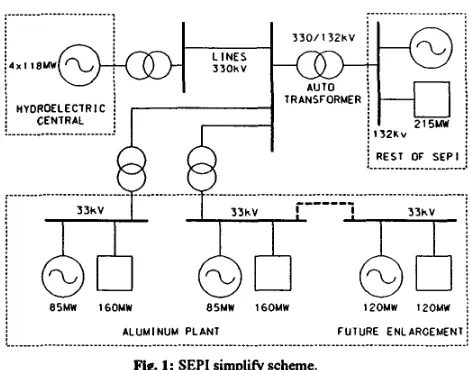
In Fig 1 is indicated
a
simplified
scheme of SEPI, showing the present situation of the aluminum plant and its futureenlargement. The values of demand of the electrolytic series, and the installed generator powers in the aluminum plant and tbe hydraulic power plant have been indicated.
There was a restriction to the power transmission on the double line of 330 kV, because the operation experience and previous studies indicate the presence of
an
electromechanical oscillation with not acceptable damping.Abstract ID
Number:
99SM
1000-7803-5569-5/99/$10.00 Q 1999 IEEE
M. Beroqui
Prof. Ppal. CICIITREE-LAT. Facultad de Ingenieria.
Universidad Nacional de La Plata (1900) 48 y 116. La Plata. Argentina
3 3 0 / 1 3 2 k V L I N E S
3 3 O k V
AUTO TRANSFORMER
i HYDROELECTRIC : j CENTRAL j
.______ ~ _.__ _.__ ____.____
__
132KvREST Of S E P I
12OMW 120MW
j BSMW 16OMW 85MW 160MW
ALUMINUM PLANT FUTURE ENLARGEMEN]
Fig. 1: SEPI simplify scheme.
By such a reason, the power hydraulic plant agent commissioned the necessary studies. These studies began with the conformation of a Database for dynamic studies, validated with data contributed by manufacturer and tests made previously.
A particular interest was put to find
a
load model that represents suitably the aluminum plant, specially in the frequency range of the electromechanical oscillations.Also, the model of the excitation control system of the
hydraulic machines was verified by tests.
Then different study scenarios were considered those include present situations and future enlargements of the
SEPI, as
much in lines, as in instaUation of new generators and new demands.As
the power hydraulic power plant is located in a SEPI far end and is the greatest generator in thissystem, all the possible participation cases in the system dispatch were analyzed, with the lowest and highest possible hydraulic head.
The
PSS
effectiveness was analyzed, with PSS working with electrical power or accelerating power signals. The reduction of thePSS
negative impact over the turbine governor was evaluated, selecting the most appropriate adjustment. Finally, tests were made in the PSS commission, to vetify their correct performance.II.
DATABASEAll the necessary models for the studies were determined
previously, from manufacturer information, or tests made in the past, or specific tests made to such aim.
In those cases when there were not test information, the recommended model and typical adjustments were taken, between many others: from [I] for the excitation controls; from [21 for turbine governors, and from [3] for the machine
[image:1.616.321.556.152.337.2]