Effect of vanadium carbide on dry sliding wear behavior of powder
metallurgy AISI M2 high speed steel processed by concentrated
solar energy
C. García
a, A. Romero
b, G. Herranz
b,⁎
, Y. Blanco
a, F. Martin
a aMaterials Engineering. E.I.I., Universidad de Valladolid. C/Paseo del cauce 59, 47011 Valladolid, SpainbE.T.S. Ingenieros Industriales. Instituto de Investigaciones Energéticas y Aplicaciones Industriales (INEI). Universidad de Castilla-La Mancha, Edificio Politécnico, Avda. Camilo José Cela s/n, 13071 Ciudad Real, Spain
a b s t r a c t
a r t i c l e i n f o
Article history: Received 1 June 2016
Received in revised form 24 September 2016 Accepted 3 October 2016
Available online 5 October 2016
Mixtures of AISI M2 high speed steel and vanadium carbide (3, 6 or 10 wt.%) were prepared by powder metallur-gy and sintered by concentrated solar enermetallur-gy (CSE). Two different powerful solar furnaces were employed to sin-ter the parts and the results were compared with those obtained by conventional powder metallurgy using a tubular electric furnace. CSE allowed significant reduction of processing times and high heating rates. The wear resistance of compacts was studied by using rotating pin-on-disk and linearly reciprocating ball-on-flat methods. Wear mechanisms were investigated by means of scanning electron microscopy (SEM) observations and chem-ical inspections of the microstructures of the samples. Better wear properties than those obtained by convention-al powder metconvention-allurgy were achieved. The refinement of the microstructure and the formation of carbonitrides were the reasons for this.
© 2016 Elsevier Inc. All rights reserved. Keywords:
Sliding wear Steel-matrix composite Wear testing Microstructure
1. Introduction
High speed steel (HSS) has been used as a cutting material frequent-ly competing with the cemented carbides in some applications[1]. HSS tool steels are also commonly used in punch and die for cold forming operations[2]. For all applications, the performance of HSS is directly re-lated to the mechanical properties of these materials like high hardness and high wear resistance. The cost involved in repairing the tooling is very high, thus, the economics implication of wear is obvious.
Conventional HSS with high vanadium contents have been used for abrasive wear items in crush industry such as hammer, jaw, rotor, etc., being that the wear resistance of which is about 3–5 times higher than that of high chromium cast irons[3]. It is well known that one way to improve the wear behavior of HSS is the addition of ceramic re-inforcements such as oxides or carbides. These composites are of diffi -cult processing and the powder metallurgy (PM) offers many advantages for the production of parts based on these materials. Several studies based on HSS composites processed by PM have been found. The additions of alumina or carbides to HSS[4,5]resulted in an important improvement of sinterability and wear behavior. In this regard the
microstructure presents a great influence in the wear behavior of the material, so the addition of TiC carbides to a matrix of high speed steel M3 Class 2 (HSS M3/2) arrested growth and propagation of cracks[6], enhanced the wear resistant of the steel[7]and increased the load car-rying capacity of the steel[8]. An improvement of sinterability and also a reinforcement of the base material was obtained by the addition of TiC
[9], Cr3C2and VC[10,11]. Some studies are specific for AISI M2 rein-forced by ceramic particles and processed by conventional PM, in which an improvement on mechanical and tribological properties was observed by adding NbC and TaC[12]or by using a tailored carbide phase[13].
While these previous examples highlight the benefit of adding small volume fractions of carbides to a metal matrix and of refining the micro-structure by conventional PM, evenfiner microstructures have been ob-tained with faster and more energetically effectivefield activated sintering techniques[14,15]. For this reason, many recent studies are based on improved the microstructures and mechanical properties of high speed steels via high energy efficiency techniques[16–18]. Con-centrated solar energy (CSE) is a technique of high energy efficiency in high temperature processes. CSE is clean, renewable and pollutant free. It comes from a natural and inexhaustible energy source and shows a clear activator effect on sintering process[19,20]. This fact can be explained looking at the solar radiation absorbed for metallic ma-terials. The energy absorbed by metals is in the UV–visible range is higher than the energy absorbed from monochromatic lasers or from the furnace as has been demonstrated by Pitts et al.[21].
⁎ Corresponding author at: E.T.S. Ingenieros Industriales. Instituto de Investigaciones Energéticas y Aplicaciones Industriales (INEI). Universidad de Castilla La Mancha, Avda. Camilo José Cela s/n, 13071 Ciudad Real, Spain.
E-mail address:gemma.herranz@uclm.es(G. Herranz).
http://dx.doi.org/10.1016/j.matchar.2016.10.001 1044-5803/© 2016 Elsevier Inc. All rights reserved.
Contents lists available atScienceDirect
Materials Characterization
The aim of the present work is to study the wear properties of the AISI M2 high speed steel parts with and without reinforcement joined to the effect of being sintered by CSE. One of the most relevant problems in the study of wear behavior is the impossibility to simulate the real ap-plication conditions. In this regard, many methodologies have been pro-posed. For example, there are more than ten ASTM standards for this purpose. These standards state that the results must not be extrapolated to service conditions and only they are valid for comparative purposes
[22,23]. The test selection is one of the major problems for the analysis of wear behavior, it is questionable the correlation between different procedures[24,25]. Therefore, it is interesting to use different wear tests using conditions test as similar as possible.
In this study, wear performance and wear mechanisms are investi-gated by using rotating pin-on-disk and linearly reciprocating ball-on-flat tests. Wear tracks are observed through scanning electron micros-copy (SEM) with energy-dispersive X-ray spectrosmicros-copy (EDX) to ex-plain the mechanisms of wear.
2. Materials and Methods
AISI M2 HSS powder andfine vanadium carbide powder, both with irregular morphology to improve the compressibility of the piece (Fig. 1), were used as starting materials. The chemical composition of the steel powder (in wt.%) is as follows: Fe 0.79C 6.39 W 1.78 V -5.11 Mo - 4.24 Cr - 0.28 Mn. The particle size distributions of both pow-ders are given inFig. 2. It can be seen that the particle size distribution of
M2 powders is wider, with a d90of 136.1μm and with a d50of 73.9μm (seeFig. 2a). Large particles of steel are used in order to improve the me-chanical properties after process by powder metallurgy[26]. The VC powder is smaller with a d90of 14μm and with d50of 6.5μm. The mix-ture of both elements presents a bimodal size distribution (seeFig. 2b). The metal powder was partially substituted by 3, 6 and 10 wt.% of VC powder, keeping a powder mass of 15 g in all cases. In order to achieve an optimal distribution of VC in M2 matrix powder, the mixtures were carried out in a planetary ball mill that allowed rotations in two direc-tions. The mixtures were milled at 50 rpm for 2 h using stainless steel balls and a ball to powder weight ratio of 4:1.
The composite powders of the different mixtures were consolidated by cold uniaxial compaction at 650 MPa. Flat and cylindrical bars were fabricated. The theoretical dimensions of the parts as replicated from the die are shown inFig. 3.
The samples were sintered in two powerful solar furnaces, one of them located at the Plataforma Solar de Almería (CIEMAT, Spain) (PSA) and the other at the Laboratoire PROcédés, Matériaux et Energie Solaire (PROMES, CNRS) (HSO) located at Odeillo (South of France). At the HSO facility, the power density achieved at the focus was 16,000 kW/m2while at the PSA facility it was 3000 kW/m2at the focus.
All sintering tests were carried out inside reactor chambers under N2-H2(95%–5%) atmosphere. The atmosphere wasflowing both during the test and for 15 min before and after preventing the oxidation of the samples. The reactors are provided of water cooling systems to avoid problems due to the high temperatures reached therein. For
comparison, the sintering experiments were also carried out in a con-ventional tubular electric furnace (TF), also under N2-H2atmosphere. The sintering conditions are specified inTable 1.
Cross sections of the sintered samples were prepared and etched with Nital's reagent (3 mL HNO3and 100 mL ethanol). The microstruc-ture of the sintered samples was analyzed by scanning electron micros-copy. Mechanical characterization was based on Vickers microhardness measurements on polished cross section surfaces, with a load of 200 g (1.96 N) applied for 10 s (HV0.2). 10 indentations were made for each sample in order to in order to ensure a correct measurement. Two test methods for wear (rotating pin-on-disk and linearly reciprocating ball-on-flat) were used.
Rotating pin-on-disk wear tests were carried out at room tempera-ture using a pin-on-disk tribometer following ASTMG99-05 standard
[22]under dry sliding conditions. An alumina ball with a diameter of 6 mm and Vickers hardness of 1500 to 1650 was used as counter-body. The disks were the sintered materials. Prior to starting the wear
test, the specimens were polished using abrasive papers up to 1μm di-amond and ultrasonically cleaned. The test was conducted with sliding velocity of 0.1 m/s and, typically, a sliding distance of 500 m. The normal load was 10.0 ± 0.1 N. The diameter of the wear tracks was 10 mm. Dur-ing the test, the dynamic coefficient of friction (COF) was continuously recorded. Wear track profiles were measured by a profilometer. The av-erage wear volume loss was obtained from at least four independent measurements for each track and the specific wear rates were calculat-ed using the conventional expression:
Wear rate mm3N−1 m−1
¼ Volume loss mm
3
Normal load Nð Þ Sliding distance mð Þð1Þ
All pin-on-disk tests were done three times to ensure repeatability. The morphology of the wear scar was observed under SEM/EDX to in-vestigate wear mechanisms.
Linearly reciprocating ball-on-flat wear tests were performed using a reciprocating-sliding tribometer, following ASTMG133-95[23], mon-itoring the static coefficient of friction (in both sliding directions). Tests were performed by applying a normal load of 10.0 ± 0.1 N to a station-ary alumina ball of diameter 6 mm with a sliding distance of 500 m. The ball-on-flat machine was set to run at 2.5 Hz with a reciprocation ampli-tude of 10 mm and without lubrication. Before each test, the specimens were polished using abrasive papers up to 1μm diamond and ultrason-ically cleaned.
After the wear tests, the morphology of each wear scar was observed by optical microscopy and SEM. The resultant wear tracks were exam-ined using profilometry to assess the general features of the wear track and to determine the volume of material removed during testing and then to calculate the specific wear rate. Finally, SEM and EDX were used to obtain information regarding the morphology and chem-ical composition of the wear debris.
It was not found significant loss of material for the alumina counter body in both experimental setups. Only slightly higher values were found for the highest reinforcement (10% of VC). Furthermore, some de-tritus was observed on the alumina ball after each test.
3. Results and Discussion
3.1. Sintering Results, Hardness and Density
Some of the results are collected inTable 2. The optimum sintering temperature (OT) is the temperature at which a best combination of density, hardness and microstructure was achieved. Optimum sintered samples were obtained in all facilities with relative densities higher than 97%. In all cases, the optimum sintering temperature decreased and the hardness increased with the addition of reinforcement. The higher the amount added of reinforcement, the more pronounced were these differences with respect to unreinforced M2 steel. The solar activation in the solar facilities accentuated these results. In the Fig. 2.Particle size distributions of (a) M2 steel powder and (b) mixtures of M2 steel and
vanadium carbide powders.
Fig. 3.Geometry and theoretical dimensions of the compacted samples.
Table 1
Sintering conditions for unreinforced and reinforced M2 steels performed in all facilities. Every sample was sintered in a 95% N2–5% H2 atmosphere.
Facility Sample identification
Content of VC (wt.%) Heating/cooling rate (°C/min) Sintering/total cycle time (min) Sintering temperature (°C)
TF M2 0 5/4 60/N600 1250–1330
M2 + 3VC 3 1220–1240
M2 + 6VC 6 1150–1240
M2 + 10VC 10 1135–1150
PSA M2 0 137/70 30/40 1115–1300
M2 + 3VC 3 1180–1200
M2 + 6VC 6 1000–1100
M2 + 10VC 10 1000–1025
HSO M2 + 3VC 3 735/110 5/12 920–1050
most powerful solar installation (HSO), sintering was obtained at around 200 °C less than in a tubular furnace for the same material. The total sintering time decreases from cycles longer than 10 h in the tu-bular electric furnace to cyclesb15 min in solar furnace at Odeillo (HSO) and 40 min in solar furnace at Almería (PSA). The sintering window (SW), the range of temperatures where the optimum densification is achieved, was smaller than 30 °C in all cases.
When comparing the hardness values obtained for the samples sintered in the tubular furnace and in the solar furnace PSA with those obtained for the other solar furnace HSO, it is observed that sintering in HSO produces higher hardness (between 910 and 930 ± 30 HV). These differences could be attributed to the heating and cooling rates,
which are the fastest in HSO. This promoted modifications of the micro-structure, that as will be detailed later, produced different precipitated species which could explain these maximum values of hardness. How-ever, the influence of the concentration of VC seems to be smaller than the use of solar energy considering that the microhardness values only rise slightly when the VC content is increased.
3.2. Microstructure
In general terms, the microstructures obtained from the three instal-lations are very similar. InFig. 4are shown typical microstructures ob-tained for each composition sintered in the tubular furnace. The Table 2
Sintering window, optimum sintering temperature, microhardness and relative density values obtained for unreinforced and reinforced M2 steel sintered in all facilities.
Facility Sample Sintering window (°C) Optimum temperatura (°C) Hardness (HV0.2) Relative Density (%)
TF M2 1292–1295 1295 620 ± 30 99,2
M2 + 3VC 1233–1235 1233 850 ± 20 97,9
M2 + 6VC 1195–1200 1200 870 ± 20 100
M2 + 10VC 1135–1145 1140 880 ± 30 98
PSA M2 1190–1200 1200 735 ± 15 100
M2 + 3VC 1180–1200 1200 765 ± 20 100
M2 + 6VC 1030–1050 1050 780 ± 20 99,7
M2 + 10VC 1015–1025 1025 800 ± 20 100
HSO M2 + 3VC 990–1025 990 910 ± 30 97
M2 + 6VC 955–975 975 930 ± 30 98
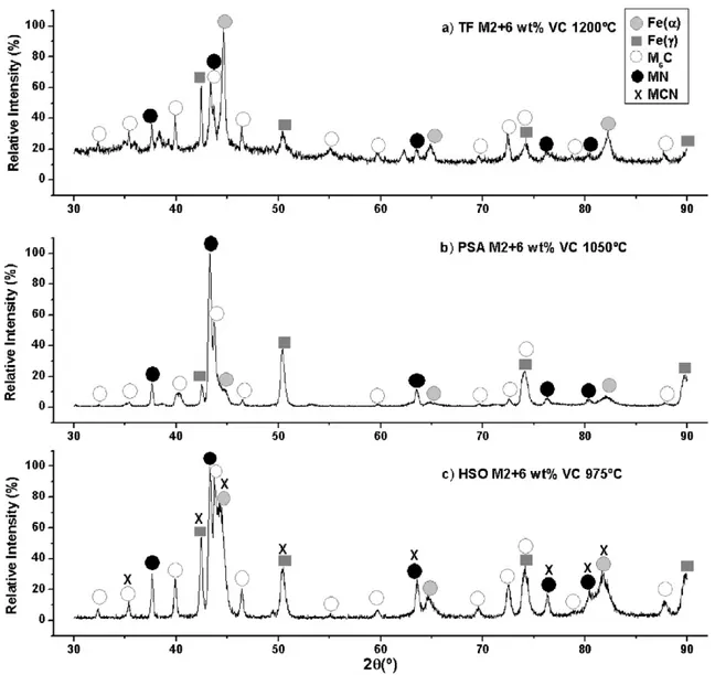
diffractograms (seeFig. 5) together with the microstructural analysis allow us to identify the different phases included. So, the matrix with gray contrast is mainly ferrite/martensite (Fe(α)), with some retained austenite (Fe (γ)). The irregular and equiaxial particles with white con-trast are identified as M6C carbides rich in molybdenum and tungsten. These carbides are typical of the structure of high speed steels and have been identified in other microstructural studies[27–29]. The par-ticles with dark contrast are MN type nitrides rich in vanadium. This last phase forming clusters appears in greater quantity when higher proportion of VC is added (seeFig. 4a-d).
The phases found in the samples sintered in the tubular furnace and in PSA are the same (seeFig. 5a-b). The most important microstructural difference found between the parts sintered in both facilities is that the samples sintered in the PSA (seeFig. 6) show evenfiner microstruc-tures. In addition, a large amount of small precipitates homogeneously distributed throughout the grain has been found in all the samples (Fig. 6a-d). This fact can be due to faster heating and cooling rates achieved in PSA, but the holding sintering time was enough to allow a complete transformation and a proper precipitation.
A new phase precipitated when the sintering process was carried out in the solar furnace at Odeillo (HSO) (seeFig. 5c and7), which was identified as carbonitrides type M (C,N)[20]. The formation of
this phase could be due to an incomplete transformation of the carbides into nitrides. The complete transformation suggested by Giménez et al.
[30]is VC + N2→V(C,N) + C→VN + C. This equation is based on the transformation enunciated by Palma et al.[31], in which VC + N2→ V(C,N) + C. Whose justification is that an increasing N pressure in the atmosphere leads to the progressive absorption of N by the material, mainly through the M(C,N) phase, which is transformed to the MN phase at the highest N pressure. However, in the HSO facility, the high heating rate (~735 °C/min) and the very short holding sintering time, only 5 min, could be responsible for the inhibition of the diffusion pro-cess as it has been previously reported by Herranz et al.[20], explaining the found incomplete transformation.
SEM/EDS was carried out to confirm the above interpretations. The EDS analysis corresponding to M2 reinforced with 3 wt.% of VC sintered in TF,Fig. 8a andTable 3, indicated that the precipitate 1 were enriched in carbon, molybdenum and tungsten as compared to the matrix. The precipitate 2 were enriched in nitrogen and vanadium. A typical compo-sition of ferrite/martensite, with about was observed in the matrix. For M2 reinforced with 3 wt.% of VC sintered in HSO,Fig. 8b, the chemical analysis of the precipitate 1 was similar to observed for composite sintered in TF indicated higher carbon, higher molybdenum and higher tungsten than in adjacent matrix. A more amount of precipitates 2 was
observed for composite sintered in HSO, these are richer in carbon than observed for composite sintered in tubular furnace. Therefore the pre-cipitates 1 can be identified as carbide type Fe3(Mo,W)3C while the pre-cipitates 2 can be identified as nitride type VN for sample sintered in tubular furnace and carbonitride VCN for composite sintered in HSO installation.
3.3. Wear Behavior
3.3.1. Pin-On-Disk Method
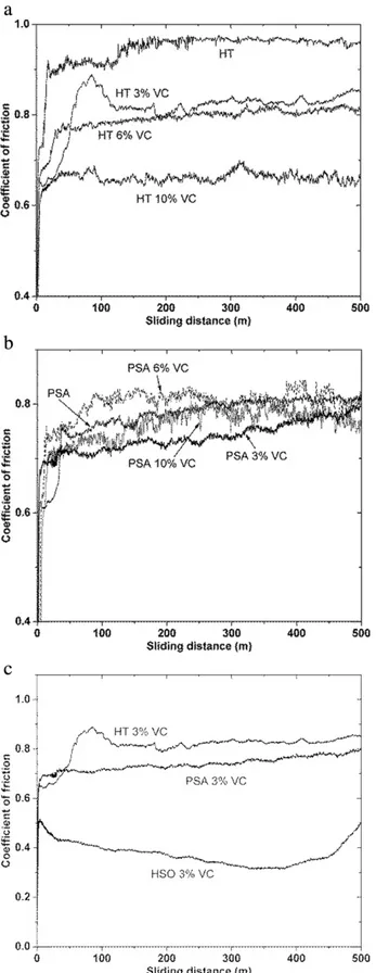
The evolution of the dynamic coefficient of friction during pin-on-disk test for samples sintered in TF and in PSA solar is shown inFig. 9a and b respectively at different concentrations of reinforcement. In all cases, the COF was characterized by localfluctuations during thefirst meters of the run while for the rest of the experiment a quasi-steady state value was reached. For TF samples there were differences as a function of concentration of reinforcement. The COF showed slowly de-creases when the concentration of VC inde-creases. In effect, the COF for M2 was around 0.95 at the end of the test while it was around 0.65 for M2 reinforced with 10 wt.% VC. A value around 0.78 was found for PSA sam-ples. The HSO samples showed the same behavior as PSA samples but with lower COF, around 0.65 except for 3 wt.% VC which was clearly lower (0.50). InFig. 9c is shown the comparative behavior for 3% of re-inforcement and for the three sintering techniques.
Table 4shows the main results regarding wear behavior of the ma-terials sintered in TF and PSA facilities. The wear rates and the average depth registered from profilometer measurements showed that the VC particles act as a real reinforcement on wear behavior. In all cases, the composite materials presented lower wear rates and lower wear depth than the base materials, which means that their wear resistance is higher and that the tendency is towards a higher wear resistance with carbide addition. For composites sintered in TF the wear behavior improved with the concentration of VC. Thus, it can be assumed that Fig. 6.Microstructures of reinforced M2 steel sintered in PSA (a and b) M2 + 6 wt.% of VC sintered at 1000 °C and (c and d) M2 + 10 wt.% of VC sintered at 1025 °C.
adding carbides help to withstand wear. This behavior agrees high the lower COF values observed for composites with high amount of rein-forcement. For composites sintered in PSA, the best wear behavior corresponded to M2 reinforced with 3 wt.% of VC. The addition of higher volumes of VC, although originated an ulterior hardening, did not pro-duced a lower volume loss. This behavior was also observed for
composites sintered in HSO, the composition corresponding to 3 wt.% of VC showed again minimum volume loss (wear rate = 0.10 10−5 mm3/N·m) in accordance with the best COF observed for this sample. The addition of 6 wt.% of VC powder deteriorate the wear resistance and an important increase of wear rate was observed (wear rate = 1.16 10−5mm3/N·m). Therefore, the effect of concentration of rein-forcement was clearly different for solar sintering and conventional sintering and similar for both solar installations although HSO gave bet-ter results.
3.3.2. Linearly Reciprocating Ball-on-Flat Method
Reciprocating wear test were used to study the tribological behavior of the M2 steel and M2 composites under a different methodology. The same counter ball and the same sliding distance were selected.Table 5
shows the average static COF for samples sintered in tubular furnace and in PSA installation. As expected the static COF was slightly higher than the dynamic COF registered with pin-on-disk apparatus. It can be seen that again the static COF decreased for composites sintered in tu-bular furnace, indicating that the reinforcement plays an important role in controlling the COF. This effect was much less important for sam-ples sintered in the solar installations. The static COF of M2 obtained by PSA were clearly lower than those obtained by TF. There are not impor-tant differences for static COF with the VC content for composites ob-tained by solar sintering. With the increase of the friction between the sample and alumina counter body sphere, the frictional heating can be expected to increase, resulting in a small temperature rise. The temper-ature during the test was directly evaluated; the results indicated that a maximum temperature of 36 °C was registered for M2 steel sample sintered in tubular furnace. This temperature increase was not observed for M2 steel sintered in solar installations, in these cases the tempera-ture was kept constant at 20 °C. For composites, there were no signifi -cant temperature changes during the tests.
Fig. 10shows the wear rate results obtained from profilometer at the end of the rotating and reciprocating tests for samples reinforced with 3 and 6 wt.% of VC content which had the better wear resistance. In gen-eral, the same trend was observed for both tests. The highest wear rate corresponded to samples sintered in the tubular furnace. For composites sintered by solar energy, the minimum values were registered for the samples with 3 wt.% of VC content. It was noteworthy that the wear rates of HSO were clearly lower than for PSA samples. As expected, the volume losses were considerably lower for reciprocating test. In general, it can be assumed that both tests are suitable to study dry wear of M2 and M2/VC composites although pin-on-disk leads to higher losses mass and therefore it is less sensible to external influences.
3.3.3. Wear Mechanisms
The tribological behavior described so far requires some discussion. The wear mechanisms of the conventional steels can be abrasive wear, adhesion, oxidation, plastic deformation, mechanical mixing and phase transformation. In this study, more than one mechanism is in-volved as will be commented. Furthermore, the COF and wear rates values are different for every material due to the microstructural differ-ences between them. The content of reinforcement and the type of sintering processing are the most important influencing factors in Fig. 8.SEM/EDS of M2 reinforced with 3 wt.% of VC (a) sintered in TF (b) sintered in HSO.
Table 3
EDS results of the M2 reinforced with 3 wt.% of VC sintered in TF and PSA facilities.
Facility Sample C (wt.%) N (wt.%) Cr (wt.%) V (wt.%) W (wt.%) Mo (wt.%) Mn (wt.%) Fe (wt.%)
TF Precipitate 1 18.22 – 2.99 1.09 31.60 19.41 0.14 26.55
Precipitate 2 11.31 19.73 2.97 57.65 1.87 1.42 0.21 4.84
Matrix 7.87 – 3.55 0.50 3.12 1.64 0.52 82.80
PSA Precipitate 1 19.57 – 3.75 5.46 23.10 13.60 0.10 34.50
Precipitate 2 18.74 12.61 0.75 57.01 1.20 1.06 0.10 5.50
friction and wear resistance in the present study. This fact indicates that wear mechanism strongly depends on the microstructure, which is in-fluenced by the composition of the sample and the sintering conditions.
Regarding the M2 steel, the sintering process plays a relevant role in the friction and wear behavior. The sample sintered in the tubular fur-nace provides the highest size of precipitates and minimum hardness and its wear and friction resistances are lower than for samples sintered in solar installations. In this case, a higher COF provides lower wear re-sistance. By having a larger COF, energy dissipation rate increases and this could increase the temperature.
The microstructure of M2 obtained in the tubular furnace revealed an important increment of V-rich particles forming clusters at the edges of the grains when the concentration of reinforcement increased. These phases are clearly visible in the samples with 3 and 6 wt.% of VC, indicating that the reaction of VC and nitrogen takes place and promotes the formation of secondary nitrides and carbides. These secondary phases have a powerful grain growth inhibiting effect and provide a strong hardening effect. Both effects justify the improvement of wear resistance observed in the composites.
The results from wear behavior of the composites processed by solar sintering are encouraging. The COF values are very similar for all the compositions although it tends to be lower when 3 wt.% of VC is added. For both solar installations, PSA and HSO, composites reinforced with 3 wt.% of VC present lower wear rate than the base material which means that their wear resistance is higher. Moreover, higher contents of carbide cause an increase on wear losses. Therefore, the wear resistance shows a maximum at the concentration of 3 wt.% of VC even though the hardness of the composite increases continuously with the amount of carbide.
On one hand, for samples sintered in PSA, the maximum density (100%) was obtained for composite reinforced with 3 wt.% of VC, a higher value of wear resistance is assigned to lower porosity levels
[32]. On the other hand, it is known that if exists an insufficient bonding between the reinforcement and the matrix or an unfavorable size and distribution of hard phases inside the matrix, the high density of car-bides produces an increase of wear rate due to the large amount of loss material when the carbides are removed[4,5].
The microstructural analysis revealed that the microstructures ob-tained in the solar furnaces had more homogeneous distribution of the carbides inside and at grain boundaries than those obtained in the tubular furnace. The secondary carbides, nitrides and carbonitrides on composites sintered in the solar installations are smaller and some of them have submicron and nanometer sizes[20]. Although the harden-ing effect of reinforcement is less intense than in the tubular furnace, an improvement of wear resistance was observed even for the lowest addition of VC. This could be explained considering that the wear mech-anisms of these materials are highly dependent of the carbides size and their cohesion with the matrix. Larger precipitates at grain boundary with low cohesion level with the matrix could easily fracture and favor the third body effects on friction and wear[33]. Smaller precipi-tates inside grain and with strong cohesion within the matrix inhibited the formation of abrasive particles. This behavior has also been observed in composites of M2 reinforced with other particles[34]. This effect was much more emphasized in the solar installations and a lower amount of VC was enough to observe the removal of precipitates and therefore is not recommendable addition larger than 3%. Therefore, M2 reinforced with 3 wt.% of VC is the optimal composition for composites sintered by solar energy and the reinforcements of 6 wt.% and 10 wt.% of VC for composites sintered in tubular furnace. These facts must be confirmed by the observation of the wear tracks with SEM.
The worn surfaces were studied by SEM/EDS (Fig. 11). This study re-veals that abrasive wear mechanism was operating in all materials. There are evidences of cohesive wear mechanism and an important amount of debris. It was observed that the pin-on-disk worn surfaces for M2 steel, composite with 3 wt.% of VC and composite with 10 wt.% of VC, all of them sintered in solar installation, were different. For com-posite, shear lips and deformed matrix were prominent (Fig. 11a) and grooving characterized the worn surface of M2 steel (Fig. 11b). These results indicate that the adhesive-induced delamination wear could Fig. 9.COF for pin-on-disk test of (a) samples sintered in TF, (b) samples sintered in PSA
dominate for composites while abrasive-induced delamination wear was taking place for M2 steel. The beneficial effect of the clusters of car-bide and nitrides in composite with 3 wt.% of VC can be observed inFig. 11c. There is much less evidence of plastic deformation on areas with secondary phases, which helps to withstand wear. This behavior is pos-sible only when particles are well linked to the matrix and cannot be easily detached. As expected, the addition of 3 wt.% of VC also generated an effective wear resistantfilm on the sliding contact surface for sample
sintered in HSO where a smooth worn surface was observed (Fig. 11d). Thefigure shows the smooth surface of compactedfine particles with fine grooves, this indicates that an abrasive wear mechanism was pres-ent. The homogeneous distribution of carbides in the matrix could also explain the greater reduction in wear rate and the low COF registered for this sample.
For composite with 10 wt.% of VC drag material and accumulation of debris increased (Fig. 11e). The EDX analysis of these areas indicated a higher oxygen and carbon content than the adjacent matrix. Conse-quently, oxidation and precipitates release took place during sliding. EDX confirmed that some black and small spots observed on the SEM micrographs corresponded to trapped alumina particles, which agrees with the fact that there is some volume loss of the pin. During the sliding wear test, the hard phase was detached on the sliding contact, which produced a three-body abrasive wear mechanism. The high hardness of this particles produce abrasive wear on the pin and therefore alumina particles can be incorporated to the debris. Because of the high contact pressure between pin and disk, these particles are encrusted in matrix.
Fig. 12shows SEM micrographs after linearly reciprocating wear for composites with 3 wt.% of VC sintered by solar energy. The wear track width is higher than the observed on rotating wear although the scar depth is clearly lower.Fig. 12a shows the scratches in the wear track of a composite sintered in PSA but much less intensive than the ob-served on rotating wear. The amount of wear debris was also small.
Fig. 12b shows primary carbides and secondary particles remaining in the wear track and helping to withstand the wear. This behavior is pos-sible because these particles are well linked to the matrix and cannot be easily detached. Similar observations can be done for composite sintered in HSO but in this case, more evidences of deformation of the matrix and lower amount of debris was found,Fig. 12c. These observa-tions agree with the lowest wear rates registered for reciprocating tests. Similar observations can be done for samples sintered in TF, but in this case, there is more abrasive wear that can explain the highest wear coefficients especially for M2 sample, Fig. 13a. Significant Table 4
Wear results of the materials sintered in TF, PSA and HSO facilities after pin-on-disk test.
Facility Sample identification Coefficient of friction Average depth (μm) Volume loss (mm3) Wear rate (10−5mm3/N·m) Microhardness (HV0.2)
TF M2 0.92 9.150 0.1050 2.10 620 ± 30
M2 + 3VC 0.84 5.100 0.0841 1.68 850 ± 20
M2 + 6VC 0.80 3.700 0.0634 1.27 870 ± 20
M2 + 10VC 0.65 1.620 0.0404 0.81 880 ± 30
PSA M2 0.80 8.150 0.0902 1.80 735 ± 15
M2 + 3VC 0.78 2.075 0.0355 0.71 765 ± 20
M2 + 6VC 0.78 2.625 0.0467 0.93 780 ± 20
M2 + 10VC 0.75 3.700 0.0620 1.24 800 ± 20
HSO M2 + 3VC 0.50 0.970 0.0071 0.10 910 ± 30
M2 + 6VC 0.65 3.200 0.0586 1.16 930 ± 30
Table 5
Wear results of the materials sintered in TF, PSA and HSO facilities after linearly reciprocating ball-on-flat test.
Facility Sample identification Coefficient of friction Average depth (μm) Volume loss (mm3
) Wear rate (10−5 mm3
/N·m) Microhardness (HV0.2)
TF M2 0.96 8.70 0.081 1.62 620 ± 30
M2 + 3VC 0.87 6.25 0.052 1.00 850 ± 20
M2 + 6VC 0.83 3.65 0.046 0.92 870 ± 20
M2 + 10VC 0.76 6.95 0.073 1.46 880 ± 30
PSA M2 0.81 7.40 0.075 1.50 735 ± 15
M2 + 3VC 0.79 1.50 0.031 0.62 765 ± 20
M2 + 6VC 0.79 1.70 0.039 0.78 780 ± 20
M2 + 10VC 0.77 1.90 0.057 1.14 800 ± 20
HSO M2 + 3VC 0.65 1.40 0.028 0.56 910 ± 30
M2 + 6VC 0.76 1.90 0.043 0.86 930 ± 30
Fig. 12.SEM micrographs of worn surfaces after linearly reciprocating ball-on-flat test of M2 + 3 wt.% of VC (a) sintered in PSA, (b) primary carbides and secondary particles remaining in the wear track and (c) sintered in HSO.
improvements in wear are also found in VC composites compared to the base materials processed by TF. However the different behavior of com-posites reinforced with 10 wt.% of VC can be explained by the micro-structures of materials and wear tracks. For composites sintered in TF, VC added in large amounts forms large size agglomerates of small parti-cles which could be detached when abraded and could be spread across the wear track. These particles act as abrasives, promoting three-body wear behavior and explaining the highest wear coefficient value ob-served in reciprocating tests,Fig. 13b. This effect was also observed for composites sintered in solar facilities when the amount of VC increases but it is less intense. In these cases, particles are encrusted in the matrix,
Fig. 13c, protecting it and leading to lower wear coefficient values. Therefore, it becomes clear that solar sintered processing is recom-mended sintering process for these composites.
4. Conclusions
The rotating pin-on-disk and linearly reciprocating ball-on-flat tests carried out on reinforced M2 steel sintered in different installations allow concluding that the resistance to dry sliding wear is a complex function of microstructure and hardness. There is a good correlation be-tween rotating and reciprocating tests although pin-on-disk leads to higher losses mass and therefore it was less sensible to external influences.
The resistance to wear is found to be the best for samples sintered by concentrated solar energy. The worst resistance behavior is observed for non-reinforced M2 steel sintered in tubular electric furnace.
The effect of the amount of reinforcement is different for conven-tional sintered and solar sintered samples. For samples sintered in the tubular furnace, an improvement of wear resistance, measured by pin-on-disk method, was observed as the concentration of VC increased. It is found to be related with an increase of hardness. However, it is enough a content of 3 wt.% of VC to achieve the best tribological proper-ties. A higher content of carbide causes an increase on wear losses even though a hardening effect was observed. This could be related with larg-er precipitates with low cohesion level with the matrix that could easily fracture and favor the third body effects on wear.
The samples sintered in HSO solar furnace showed the best tribolog-ical behavior. For HSO, sintering is more energettribolog-ically activated. It orig-inates a more homogeneous andfiner microstructure with new phases and with nanometer sizes in the minimum time that provides the highest microhardness and the highest wear resistance.
The use of concentrated solar energy is able to produce metal matrix composite with a particular microstructure development and with bet-ter microhardness and tribological properties than those obtained by using traditional methods of processing. In addition, a much lower time of processing is achieved.
Acknowledgements
The authors gratefully acknowledge thefinancial support by JCCM in the Spanish National Programme (Project PPIC10-0052-5968). The au-thors thank the use of the facilities and its researchers/technology ex-perts: through the IP3 FP6 ESTEEM project under contract No. 026019 by means of the programme“Acceso a Grandes Instalaciones”at PSA fa-cility, and by the Access to Research Infrastructures Activity in the 7th Framework Programme of the EU (SFERA Grant Agreement n. 228296) at the PROMES-CNRS Solar facility.
References
[1] G. Hoyle, High speed steel, Butterworth and Co, Cambridge, 1988. [2] J.R. David, Heat-Resistant Materials, ASM Specialty Handbook, Ohio, 1997.
[3] S.Z. Wei, J.H. Zhu, L.J. Xu, Research on wear resistance of high speed steel with high vanadium content, Mater. Sci. Eng. A 404 (2005) 138–145.
[4] J.M. Torralba, L.E.G. Cambronero, J.M. Ruiz-Prieto, M.M.d. Neves, Sinterability Study of PM M2 and T15 High Speed Steels Reinforced with Tungsten and Titanium Car-bides, Powder Metall. 36 (1) (1993) 55–66.
[5] W.C. Zapata, C.E. Costa, J.M. Torralba, Sinterability and wear behavior of P/M M2 high speed steel reinforced with NbC composite, J. Mater. Process. Technol. 53 (1995) 483–490.
[6] B. Martin, L. Vincent, C.S. Wright, A.M. Eagles, A.S. Wronski, Fretting wear and crack-ing in sintered metal matrix composites, Wear 248 (2001) 65–74.
[7] L. Zuomin, T.H.C. Childs, The study of wear characteristics of sintered high speed steels containing CaF2, MnS and TiC additives at elevated temperature, Wear 257 (2004) 435–440.
[8] Z. Zalisz, A. Watts, S.C. Mitchell, A.S. Wronski, Friction and wear of lubricated M3 class 2 sintered high speed steel with and without TiC and MnS additives, Wear 258 (2005) 701–711.
[9] M.M. Oliveira, J.D. Bolton, Sintering of M3/2 HSS modified by additions of copper phosphide and titanium based ceramic compounds, Powder Metall. 38 (1995) 131–140.
[10] E. Pagounis, M. Talvitie, V.K. Lindroos, Microstructure and mechanical properties of hot work tool steels matrix composites produced by hot isostatic pressing, Powder Metall. 40 (1997) 55–61.
[11] E. Pagounis, V.K. Lindroos, Processing and properties of particulate reinforced steel matrix composites, Mater. Sci. Eng. A 246 (1998) 221–234.
[12] E. Gordo, F. Velasco, N. Antón, J.M. Torralba, Wear mechanisms in high speed steel reinforced with (NbC)p and (TaC)p MMCs, Wear 239 (2000) 221–234.
[13] J. Richter, Tribological evaluation of high-speed steels with a regulated carbide phase, Mater. Charact. 50 (2003) 339–347.
[14] J.R. Groza, Nanosintering, Nanostruct. Mater. 12 (1999) 987–992.
[15] J. Zhang, A. Zavaliangos, J.R. Groza, Field activated sintering techniques: a compari-son and contrast, P/M Sci Technol Briefs 5 (2003) 5–8.
[16] W.H. Dennis, Refining carbide size distributions in M1 high speed steel by process-ing and alloyprocess-ing, Mater. Charact. 46 (2–3) (2001) 175–182.
[17] H. Wang, L. Hou, J. Zhang, L. Lu, H. Cui, J. Zhang, The secondary precipitates of niobi-um-alloyed M3:2 high speed steel prepared by spray deposition, Mater. Charact. 106 (2015) 245–254.
[18]L. Lu, L.G. Hou, J.X. Zhang, H.B. Wang, H. Cui, J.F. Huang, Y.A. Zhang, J.S. Zhang, Im-proved the microstructures and properties of M3:2 high-speed steel by spray forming and niobium alloying, Mater. Charact. 117 (2016) 1–8.
[19] G. Herranz, A. Romero, V. de Castro, G.P. Rodríguez, Development of high speed steel sintered using concentrated solar energy, J. Mater. Process. Technol. 213 (2013) 2065–2073.
[20] G. Herranz, A. Romero, V. de Castro, G.P. Rodríguez, Processing of AISI M2 high speed steel reinforced with vanadium carbide by solar sintering, Mater. Des. 54 (2014) 934–946.
[21] Solar induced surface transformation of materials, in: J.R. Pitts, J.T. Stanley, C.L. Fields, B.P. Gupta, T. W.H. (Eds.), Solar Thermal Technology-Research Development and Applications, Hemisphere Publishing Corporation, New-York, USA 1990, pp. 459–470.
[22]ASTM, Standard G99, Standard Test Method for Wear Testing with a Pin-on-Disk Apparatus, ASTM International, West Conshohocken, PA, USA, 2008.
[23] ASTM, Standard G133, Standard Test Method for linearly Reciprocating Ball-on-Flat Sliding Wear, ASTM International, West Conshohocken, PA, USA, 2008.
[24]J.A. Hawk, R.D. Wilson, J.H. Tylczak, Ö.N. Dogan, Laboratory abrasive wear test: in-vestigation of methods and alloy correlation, Wear 225-229 (1999) 1031–1042. [25]P.J. Blau, K.G. Budinski, Development and use of ASTM standards for wear testing,
Wear 225-229 (1999) 1159–1169.
[26] Powder Metallurgy Processing and Materials, European Powder Metallurgy Associ-ation (EPMA), 1997.
[27] D. Peidao, S. Gongqi, Z. Shouze, A scanning electron microscopy study of carbides in high-speed steels, Mater. Charact. 29 (1992) 15–24.
[28] D.W. Hetznera, W. Van Geertruyden, Crystallography and metallography of carbides in high alloy steels, Mater. Charact. 59 (2008) 825–841.
[29]M. Godec, B.Š. Batič, D. Mandrino, A. Nagode, V. Leskovšek, S.D.Škapin, M. Jenko, Characterization of the carbides and the martensite phase in powder-metallurgy high-speed steel, Mater. Charact. 61 (2010) 452–458.
[30] S. Giménez, C. Zubizarreta, V. Trabadelo, I. Iturriza, Sintering behaviour and micro-structure development of T42 powder metallurgy high speed steel under different processing conditions, Mater. Sci. Eng. A 480 (2008) 130–137.
[31] R.H. Palma, V. Martínez, J.J. Urcola, Sintering behaviour of T42 water atomized high speed steel powder under vacuum and industrial atmospheres with free carbon ad-dition, Powder Metall. 32 (1989) 291–299.
[32] F. Martin, C. García, Y. Blanco, Influence of residual porosity on the dry and lubricat-ed sliding wear of a powder metallurgy austenitic stainless steel, Wear 328-329 (2015) 1–7.
[33] N. Diomides, S. Mischler, Third body effects on friction and wear during fretting of steel contacts, Tribol. Int. 44 (2011) 1452–1460.