An Embedded Real-Time Co-Processor for Control Applications
R. Cayssials, O. Alimenti, F. Luque and E. Ferro Universidad Nacional del Sur - CONICET
Department of Electrical Engineering Bahía Blanca - Argentina
{iecayss}@criba.edu.ar
Abstract
In this paper we present a high performance real-time microcontroller (uRT51) based on an 8051 core. The uRT51 is an 8-bits processor that includes a Real-Time co-processing unit. We have implemented the speed control of a DC motor to evaluate the uRT51 performance. The uRT51 shows a control performance suitable for low-cost, low-power, embedded real-time control applications in which real-time systems based on RTOS fail.
KeyWords: Real-Time Systems, Real-Time Co-Processing, Embedded Systems.
1.
Introduction
Digital control utilises real-time systems to control systems. A typical control system is made up of a set of control tasks in addition to other non-control tasks (like user interaction, health monitoring, etc). Digital control techniques are applied to design efficient control strategies. These techniques are based on discrete-time models that require to meet strict timing intervals. Hence, the precision on these temporal requirements should be used to evaluate the control performance that the real-time systems can achieve.
Real-time systems consist of a set of tasks that has to be executed by a processor. Most of real-time systems are implemented using a Real-Time Operating System (RTOS). The scheduler is a special task of the RTOS that shares the processor among the tasks that require execution. The scheduler implements a priority discipline to determine the next task to be executed. The execution of the scheduler produces overhead on the systems.
Several approaches have been proposed to implement processors with real-time features. In [1, 3, 5], a co-processor architecture is proposed to support real-time applications. It implements RTOS functions over a reduced set of tasks. In [6, 7], the AAMP processor is shown to be used in avionics. The AAMP was verified to have a predictable behaviour, but it does not have special real-time features. In [9], the δ Framework is proposed as a method to implement RTOS functions in a reconfigurable hardware. None of these approaches are available for commercial, industrial or educational developments. They are very restrictive on both the priority discipline implemented and the number of tasks supported. Besides, all these approaches are evaluated considering scheduling parameters (e.g. tasks' response times, missed deadlines, idle cpu-time, etc.) instead of evaluate the effects that they produce on the controlled application.
The uRT51 is a processor designed to be applied in embedded real-time applications. Its architecture was designed from a real-time point of view and consequently any arbitrary priority discipline can be implemented over a set of up to 65000 tasks. The URT51 is available together with the uRT51 Programming Suite that allows the designer to program, to debug and to analyse its application.
In this paper we evaluate the performance of the uRT51 processor in a control application. We propose a speed control of a DC motor to compare the performance of the uRT51 processor with the one obtained using a RTOS. The experiments show that the uRT51 outperforms a RTOS-based time system. It is shown that the uRT51 is suitable for low-cost, low-power embedded real-time control applications.
Section 2 introduces the main concepts on digital control. Section 3 describes a typical implementation of a real-time operating system. In section 4 we present the effects that a scheduling mechanism produces on the control tasks. The architecture of the uRT51 processor is shortly explained in section 5. In section 6 we demonstrate how to control the speed of a DC motor using the uRT51 processor. In section 7 the performance of the uRT51 was evaluated for the four real-time tasks of the application implemented. Results are analysed in section 8. Conclusions are drawn in section 9.
2.
Digital Control
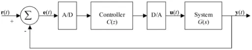
The basic operation of a digital control system (Fig.1) is to read information from multiple sensors, calculate the output and send the results to actuators.
The control application is mathematically modelled by the transfer function G(s). The control design problem is to specify the transfer function C(z) to give to the closed-loop the desire characteristics. These characteristics include stability and perhaps some specification on the step response such as the percent overshoot, settling time, and steady-state error.
model of the control application. The discrete-time model derived from this transformation is not an
approximation but an exact description of the behaviour of the application at sampling intervals
([4]).
The computational execution of C(z) takes some time to complete. If the computational delay is very small compared with the dynamic of the system, it can be neglected. Anyway, a good design should take into account this delay in order to assess the effect of time delay on the close-loop and decide whether or not it is negligible.
[image:3.595.170.426.246.297.2]A variable sampling interval during runtime produces a jitter that is not modelled by the discrete-time model and consequently it could lead to an undesirable behaviour of the application. Real-discrete-time systems should be design in order to reduce/eliminate the jitter on both the sampling interval of the inputs and the updating interval of the actuators.
Figure 1: Classical Feedback Discrete-Time Control System. C(z) is the transfer function
of the controller and G(s) is the transfer function that models the application.
3.
Real-Time Operating System (RTOS) Functions
A real-time system is modelled as a set Π of n periodic tasks to be executed on a processor. Each task i performs a certain function and it is characterised by its period, Ti, its deadline, Di, and its execution time, Ci.
Tasks must be invoked periodically according to its period. This can be done by a timer associated to each task. However, as the number of tasks increases, a lot of systems resources would be consumed by these timers. Instead, most of RTOS runs a time-based task invoked by a periodic timer interrupt that goes off at regular intervals and checks whether a real-time task has to be invoked or not ([2]). Because the timer task is invoked at discrete intervals, denoted Ttimer, the time in a real time system is considered slotted and either tasks’ periods and tasks’ deadlines should be expressed in slots. Therefore, task i will have to be invoked either every ⎣Ti/Ttimer⎦ or every ⎡Ti/Ttimer ⎤ slots.
For instance, if timer task is set to go off every Ttimer = 500µs, a real time task with a period of T = 1.6ms, should be invoked either every 3 slots (1.5 ms) or 4 slots (2 ms). In both cases there exists a drift in the task invocation.
The scheduler is executed after the timer task in order to determine the task that grants the processor in the next slot. Hence, Ttimer has influence either on the system time resolution as well as the overhead that the RTOS produces.
4.
Real-Time Scheduling of Control Tasks
Scheduler assigns the processor according to the priority discipline that it implements. The fixed priority (FP) is one of the most important disciplines in real-time and most of RTOSs implement it. In a FP discipline each real-time task is assigned with a priority in the design time and it remains fixed during runtime.
If each real-time task of the system meets its deadline, then it is said that the system is schedulable. Real-time advance techniques compute the worst case of response of any real-time task of the system in order to analyse its schedulability.
interference and therefore a variable response time of the task. These time variations produce a jitter on both input sampling and output updating of the control system.
A real-time task may be executed immediately after its invocation or may be completed just before its deadline. The maximum absolute jitter of task i is equal to Diand consequently a real-time task i could produce a sampling interval, Sisuch that:
i i i i
i D S T D
T − ≤ ≤ + (1)
This leads to a relative jitter of ± Di/Ti. Shorter deadlines improve the control performance of the system but require more powerful computational processors to make the system schedulable.
5.
The uRT51 processor
The uRT51 is a processor intended for low-power, control, real-time, embedded applications. The uRT51 microprocessor is available in VHDL and can be synthesised for Altera, Xilinx and ASIC devices. The uRT51 Programming Suite is an IDE environment to program, to debug and to analyse an uRT51 application. The authors can supply all the tools required to work with the uRT51 processor.
uP core Real-Time
Unit Debugging
Unit clk
Memory Controller
RAM
Flash
I/O uRT51 Programming Suite
[image:4.595.195.386.341.445.2]uRT51
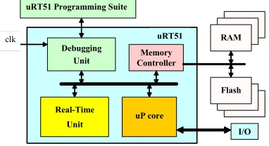
Figure 2: The uRT51 processor architecture
The uRT51 processor consists of the following building blocks (Figure 2):
• The uP core implements a subset of the 8051 instruction set and it can recognise some special real-time instructions to be executed by the Real-Time unit. Input/Output devices can be driven directly by the uP core.
• The Real-Time Unit controls the real-time behaviour of the uRT51 processor. It is a co-processing unit that supports any arbitrary priority discipline and up to 65000 tasks. When no task is requiring to be executed, real-time unit halts all the uRT51 activities and consequently it reduces the power consumption of the system.
• The Debugging Unit allows an easy integration with the uRT51 Programming Suite. All the activities of the uRT51 can be controlled and supervised by the uRT51 Programming Suite through the Debugging Unit.
• The Memory Controller implements all the control functionality to connect the uRT51 processor to external memories. It supports different bus widths. Input/Output devices can be connected in the uRT51’s Memory Map.
6.
DC Motor Speed Control
In this section we describe the application we used to evaluate the performance of the uRT51processor.
6.1.Description of the application
The speed of the DC motor is controlled varying the energy transferred to the motor using a pulse width modulation (PWM) technique.
The PWM technique is based on changing the duty cycle of the power supplied to the motor. The duty cycle is defined as the ratio between the time that the power is on and the period of the wave (Fig.3). The energy supplied to the motor when the power is on is converted to mechanical movement of the motor. When the power is off, the motor remains moving because the energy that was transferred when the power was on. However, the power should be connected before the velocity of the motor decay below a certain value. Therefore, the period of the PWM wave, denoted
TPWM, depends on both the electrical and the mechanical characteristics of the motor and the load. In our case, good velocity stability was achieved for PWM periods between 10ms and 20ms. The resolution on the motor speed will depend on the precision we could get on both the time that power is on and the period of the PWM wave.
Ton
TPWM
Figure 3: PWM wave of the power supplied to the motor to control its velocity. The energy transferred to the motor is proportional to the duty cycle of the wave ( Ton/TPWM).
Real-Time System
Task 2 Task 4
Task 3
Task 1
DC Motor Power
Supply PWM Control
DC Motor
Sensor Communication
Interface
Sensor data acquisition Current Speed
Speed calculus
toogles’ count Setpoint
To remote control and supervision
[image:6.595.191.405.102.400.2]Application
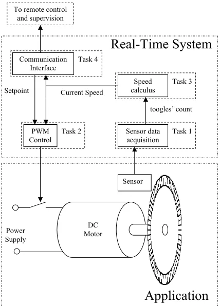
Figure 4: Scheme of the DC motor speed control. The PWM module controls the energy supplied to the motor and the sensor toggles its output every 2·π36 rad.
In order to reduce the error in the calculus of the velocity, the interval Isconsidered should be long enough. If the interval is short, then the influence of one toggle will produce great variations on the speed calculus. However, as Isincreases, the response of the motor to changes in the load or in the setpoint of the speed will decrease. As a tradeoff between both considerations, we chose an interval equal to 23ms.
The speed setpoint is configured by a remote computer through a serial link. In this way, control and supervision of the motor can be done remotely using a standard communication link.
6.2.Specification of the real-time system
Four well define real-time tasks can be defined from the control functions that the system must perform (Fig.4).
• Task 1: Data Acquisition
This task is in charge of monitoring the sensor and counts the number of toggles that the sensor produces on its output. The task period should be less than 347.22 µs in order to avoid missing output toggles.
• Task 2: PWM control
Task 2 modifies the duty cycle of the PWM wave according to the difference between the setpoint and the speed of the motor. If the speed of the motor is lower than the setpoint, then the duty cycle of the PWM wave is increased, otherwise it is decreased. Task 2 is invoked m times every PWM wave period. Each time that task 2 is invoked, it checks if the power of the motor should be turn either on or off to produce the desire duty cycle.
• Task 3: Speed calculus
Task 3 calculates the speed of the motor through the angle elapsed in the interval Is. There exists a trade-off on the Is selection between the precision and the reaction of the system. As Isincreases, the error in the calculus of the speed of the motor decreases but the reaction of the control to changes on both the setpoint and the motor load becomes slower. However, a higher precision on the calculus of the speed allows us to increase the gain of the PWM control and consequently reacts faster to changes on both the setpoint and load conditions. A boundary on the precision in the calculus of the speed should be given by the precision we can get on the PWM control. There is not point to get a higher precision on the calculus of the speed if it is not possible to control it in a comparable magnitude.
• Task 4: Communication interface
This task sends to and receives from, through an asynchronous serial link working at 960 bytes/s, the current speed of the motor and the setpoint, respectively. In order to avoid missing bytes received through the serial link and to transmit at the maximum transmission rate, task 4 should be invoked at least every 1 / 960 s ≈1ms.
7.
Evaluation
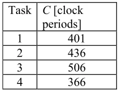
Whilst periods and deadlines depend on the functions that control tasks must perform, the execution time depends on the computational characteristics of the processor. The four real-time tasks were implemented to be executed on the uRT51 processor. The worst case execution time of each task is given in system clock period units on the Table 1.
Task C [clock periods]
1 401
2 436
3 506
[image:7.595.238.357.415.507.2]4 366
Table 1: Worst case execution time of the tasks of the system expressed in clock periods
The priority assignment is done according to a rate monotonic policy (RM). In RM, tasks with shorter periods are assigned to higher priorities. Table 2 shows the period, the deadline and the priority of each one of the real-time tasks. Higher priorities are represented by lower priority indexes.
Task T D Priority
1 347.22µs 347.22µs 0 (highest)
2 1ms 1ms 1
3 23ms 23ms 3
4 1ms 1ms 2
Table 2: Period, deadline and priority of the real-time tasks
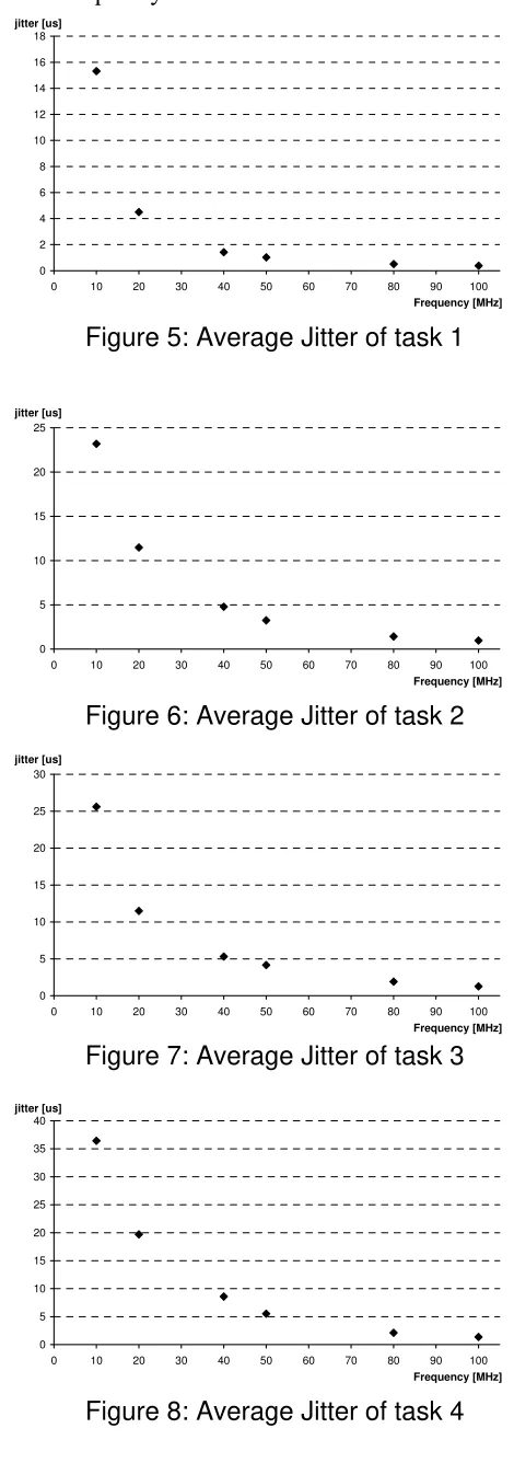
A timer/scheduling mechanism was implemented for four tasks. The evaluation of the system was performed using a FPGA development board to implement them. Clock frequencies were set to 10, 20, 40, 50, 80 and 100MHz. The uRT51 Programming Suite was used to program the system and to analyse the runtime behaviour of the systems.
[image:7.595.198.400.596.683.2]The uRT51 processor can schedule the system with a 10MHz clock frequency while the RTOS-based system needs at least a frequency of 50MHz to schedule it because the RTOS overhead.
0 2 4 6 8 10 12 14 16 18
0 10 20 30 40 50 60 70 80 90 100
Frequency [MHz] jitter [us]
Figure 5: Average Jitter of task 1
0 5 10 15 20 25
0 10 20 30 40 50 60 70 80 90 100
Frequency [MHz] jitter [us]
Figure 6: Average Jitter of task 2
0 5 10 15 20 25 30
0 10 20 30 40 50 60 70 80 90 100
Frequency [MHz] jitter [us]
Figure 7: Average Jitter of task 3
0 5 10 15 20 25 30 35 40
0 10 20 30 40 50 60 70 80 90 100
[image:8.595.172.407.121.789.2]Frequency [MHz] jitter [us]
8.
Result Analysis
From the point of view of the real-time scheduling theory, the overhead of the system is reduced when the uRT51 is used. Besides, with an uRT51 processor the system is schedulable at lower clock frequencies with the following advantages:
• the power consumption of the system is reduced. The power dissipation of a digital is proportional to the clock frequency of the system. Besides, the voltage of the system can be driven down and consequently the power consumption of the system is reduced [8].
• lower cost technology can be used. When lower clock frequencies are applied, cheaper technologies can be used in the processor implementation.
• the electromagnetic interference is reduced when lower clock frequencies are applied and consequently systems can meet standards easily.
On the other hand, from a control theory point of view, the performance is improved when a uRT51 processor is utilised because the average jitter of the tasks is much less. In a real-time system based on a RTOS, the slot time has a greater influence on the control performance than the clock frequency.
9.
Conclusions
In this paper we evaluate experimentally the performance of the uRT51 processor in a control application.
The uRT51 processor requires a much less frequency to schedule the real-time system. Whilst the uRT51 processor schedules the DC motor speed control application with a 10 Mhz clock, a RTOS needs at least a 50Mhz clock. Better and cheaper digital designs can be achieved at lower clock frequencies.
The control properties of the real-time system are improved because the jitter of the control tasks is reduced. Consequently, the perturbations that the real-time system produces on the control application are reduced as well.
We can conclude that the characteristics of the uRT51 processor make it suitable to be applied to low-cost, low-power embedded real-time control applications.
References
[1] M. Colnaric andW.A. Halang. Architectural support for predictability in hard real time systems.
Control Engineering Practice, 1(1):281–285, 1993.
[2] Bill O. Gallmeister. POSIX.4: Programming for the Real World. O’Reilly & Associates, January 1995.
[3] Vlado Glavini´c, Stjepan Gros, and Matjaz Colnari ´c. Vhdl-based modeling of a hard real-time task processor. InIEEE ISIE’99, pages 49–54, Bled, Slovenia, 1999.
[4] Vaccaro Richard J. Digital Control: A State-Space Approach. McGraw-Hill Series in Electrical
and Computer Engineering, 1995.
[5] W.A. Halang M. Colnaric, D. Verber. Supporting high integrity and behavioural predictability of hard real-time systems. Informatica, Special Issue on Parallel and Distributed Real-Time
Systems, 19(1):59–69, February 1995.
[6] Mandayam K. Srivas and Steven P. Miller. Formal verification of an avionics microprocessor. Technical Report CSL-95-04, SRI Internaltional Computer Science Laboratory, Menlo Park CA 94025, USA, June 1995.
[7] Matthew M. Wilding Steven P. Miller, David A. Greve and Mandayan Srivas. Formal verification of the aamp-fv microcode. Contractor Report NASA/CR-1999-208992, National Aeronautics and Space Administration, 7121 Standard Drive, Hanover, MD21076-1320, February 1999.
[8] Clive Watts and Ravi Ambatipudi. Dynamic energy management in embedded systems. IEEE
[9] Jaehwan Lee and J. Lee and V. J. Mooney III and K. Ingstrom and A. Daleby and T. Klevin and L. Lindh, "A Comparison of the RTU Hardware RTOS with a Hardware/Software RTOS", In