A Genetic Based Neuro-Fuzzy Controller for Thermal Processes
Ashok Kumar Goel
Department of Electronics Engg., GZS College of Engg. & Technology Bathinda, Punjab 151 001, India
Suresh Chandra Saxena
Director, Thapar Institute of Engg. & Technology, Patiala, Punjab 147 001, India
and Surekha Bhanot
Instrumentation Group, Birla Institute of Tech. & Science, Pilani, Rajasthan 133 031 India
ABSTRACT
This paper presents a neuro-fuzzy network where all its parameters can be tuned simultaneously using Genetic Algorithms. The approach combines the merits of fuzzy logic theory, neural networks and genetic algorithms. The proposed neuro-fuzzy network does not require a priori knowledge about the system and eliminates the need for complicated design steps like manual tuning of input-output membership functions, and selection of fuzzy rule base. Although, only conventional genetic algorithms have been used, convergence results are very encouraging. A well known numerical example derived from literature is used to evaluate and compare the performance of the network with other modelling approaches. The network is further implemented as controller for two simulated thermal processes and their performances are compared with other existing controllers. Simulation results show that the proposed neuro-fuzzy controller whose all parameters have been tuned simultaneously using GAs, offers advantages over existing controllers and has improved performance.
Keywords: Neuro-fuzzy controller, fuzzy logic,
modelling, neural networks, genetic algorithms.
1. INTRODUCTION
Fuzzy logic control systems have the capability of transforming linguistic information and expert knowledge into control signals and are preferred over traditional approaches such as optimal and adaptive control techniques. Despite advantages of the conventional fuzzy logic controller (FLC) over traditional approaches, there remain a number of difficulties in design stages. Hybrid controllers built by combining fuzzy logic with allied technologies like neural networks and genetic algorithms not only help in overcoming some of these difficulties but also render many advantages:
i) FLCs are characterized by a number of parameters that are needed to be configured in prior, such as input/output scaling gains, the centre and width of membership functions, and selection of appropriate fuzzy control rules. The complexity in selection of these parameters increases with the complexity of process.
ii) Artificial neural networks, due to their learning capability, are being sought in the development of neuro-fuzzy controllers or adaptive FLCs. Berenji [1] developed a FLC that is capable of learning as well as tuning its parameters by using neural networks trained through a reinforcement learning method. Jang [2] developed a self-learning FLC based on a neural network trained by temporal back-propagation. iii) Karr and Gentry [3] applied Genetic Algorithms
(GAs) in the tuning of fuzzy membership functions to a pH control process. Varsek et al. [4] used GAs to tune FLC in three phases: learning of basic control rules, rules compression, and fine tuning. Farag et al [5] also proposed a neuro-fuzzy modelling and control methodology where three algorithms are used in phases to tune network parameters. iv) Partial or stage by stage optimization of FLC
parameters and control rules restrict the searching spaces of GAs. Thus, it results in higher possibility of partial or sub-optimal solutions. As each of the design stages of the FLC may not be independent, it is important to consider and optimize them simultaneously. v) Lee and Takagi [6] proposed a method of
determining all parameters simultaneously using GAs for a Takagi-Sugeno [12] type of FLC. Shimojima et al. [7] and Seng et al [8] used GAs to tune a RBF neural network based fuzzy model which does not use fuzzy output membership functions. This type of knowledge representation does not allow the output variables to be described in linguistic terms. This is one of the major drawbacks of this approach.
In this paper, a five layer Multilayer Perceptron network is configured as a neuro-fuzzy network (NFN). The consequent terms are also represented by linguistic terms, which make this model more intuitive and give more insight into the model structure. All parameters of the NFN including fuzzy rules are simultaneously tuned using GAs.
Layer Layer Layer Layer Layer
[image:2.595.89.266.91.284.2]1 2 3 4 5
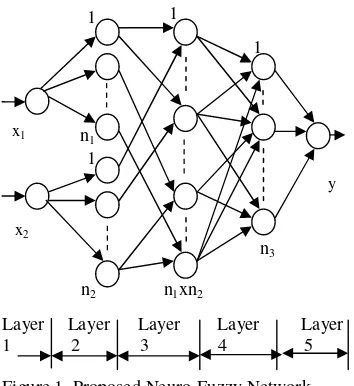
Figure 1. Proposed Neuro-Fuzzy Network
[9] and Farag et al [5], ii) a water-bath system, which is an example of an important component in a batch reactor process [15] and iii) Continually Stirred Tank Heater (CSTH), a input multi-output (MIMO) interacting process [16]. Both these processes are widely used in chemical industry. The initial GA populations for the three problems are randomized, which implies that minimum heuristic control knowledge about the process is required. All parameters of neuro-fuzzy controller (NFC) are simultaneously tuned using GAs.
2. NEURO-FUZZY NETWORK The neuro-fuzzy model is built using a multilayer fuzzy neural network shown in figure 1. The system has a total of 5 layers as proposed by Lin and Lee [10] and Farag et al [5]. Here, a model with 2 inputs and a single output is considered. Accordingly, there are two nodes accounting for two inputs in layer 1 and one output node in layer 5 (the output layer). The nodes in layers 2 & 4 account for membership functions of fuzzy linguistic input and output variables respectively. The fuzzy sets of two input variables and the lone output consist of n1, n2and n3
linguistic terms, respectively. Hence, n1+ n2 nodes
in layer 2 and n3nodes in layer 4 are included.
There are (n1x n2)nodes in layer 3 to form a fuzzy
rule base for the two linguistic input variables. The links of layers 3 and 4 define preconditions and consequences of rule nodes, respectively. For each rule node, there are two fixed links from input term nodes. Layer 4 links are adjusted in response to varying control situations. By contrast, links of layers 2 and 5, between input-output nodes and their corresponding term nodes, remain fixed and equal to unity.
The neuro-fuzzy model can adjust fuzzy rules and their membership functions by modifying links of layer 4 and parameters that represent the guassian membership functions for each node in layers 2 and
4. The following notations are used to describe the functions of the nodes in each of the five layers:
L i
x Input value to the ithnode in layer L.
L i
y Output value of the ithnode in layer L.
L i L i
m ,σ Centre and width of the Gaussian function of the ith node in layer L.
ij
w Weight connecting the output of jthnode in
layer 3 to the ithnode in layer 4.
Layer 1: The input layer, directly transmits input signals to the next layer.
1 1
y = x11,
1 2
y = x12. (1)
Layer 2: This layer fuzzifies the numerical input by applying Gaussian membership function.
2
i
x = 1
1
y for i = 1,2…,n1
= y12 for i = n1+1,…,n1+n2 (2) 2
2 2 2 2
exp− − =
i i i i
m x y
σ for i=1,2,…,n1+n2 (3) Layer 3: The links in this layer perform a conjunctive operation in the ‘premise’ part of the fuzzy rules. Thus, each node has two input values from layer 2.
(
2 2)
3
, k
j
i y y
y =Π for j = 1,2,…,n1 (4)
k = n1+1,…, n1+n2
i = n1(j-1) + (k-n2)
Link weights in this layer are also set to unity. Layer 4: The weight Wijfor this layer expresses the
interconnection strength of the jth rule with the ith output linguistic variable. For each rule, the correct consequent (output linguistic term) is identified by a simple procedure outlined below:
for j = 1 to n1*n2
for i = 1, n3
find max(wij)
label its consequent link as imax
assign wij = wijfor i=imax
= 0 otherwise end
end
Each node of this layer performs the disjunction (OR) operation to integrate the fuzzy rules leading to the same output linguistic variable. The output of the nodes in this layer is given by:
=
= 1 2
*
1 3 4
.
n n
j j ij
i w y
y for i = 1,2, …,n3 (5)
Layer 5: This layer acts as a defuzzifier and computes the output signal of the neuro-fuzzy network. The center of area defuzzification scheme is used in this model and is given as follows:
= =
= 3
1 4 4 3
1 4 4 4 5
1 n
j j j n
j
j j j
y y m y
σ σ
(6) x1
x2
y 1
1
1
1
n3
n2 n1xn2
3. TUNING OF NEURO-FUZZY NETWORK USING GAs.
GAs are powerful search optimization algorithms based on the mechanism of natural selection and genetics. Because of the robustness, these are successfully applied to generate if-then rules and membership functions of fuzzy systems [3, 4, 11]. The proposed neuro-fuzzy network (NFN) is tuned using GAs. All parameters of the network are initially randomized, and then tuned and optimized simultaneously by GAs. The problem makes use of supervised learning and can be stated as: “Given the training input data xi(t), i=1,…,n, the desired output
value yi(t), i=1, 2, …,m, fuzzy partitions {P(x)} and
{P(y)}, shapes of membership functions, and fuzzy rules are to be optimally adjusted”.
The GA is coded using MATLAB. Typical values of different parameters of GAs are taken [17]. The programs use static values for maximum number of generations (maxgen=1000), probability of crossover (pc=0.9), and probability of mutation (pm=0.05). The initial population is randomly generated. The population size (psize=30), is selected based on the observations made by Farag et al. [5].
The number of alleles (values which make up the string) is determined from the total number of fuzzy sets used to partition the space of the input-output variables. For the network configuration shown in figure 1, we have (n1+ n2+ n3 = n4) membership
functions. Each gaussian-shaped membership function is defined by two parameters (the center m, and the width )σ . To optimize the membership functions, we have to optimize (n4x 2) parameters.
Further, we have (n1 x n2 x n3 = n5) possible
combinations of rules in the rule base, out of which optimal (n1x n2)rules are to be selected. Thus, the
GA uses strings of length (n4x 2 + n5) alleles. Each
parameter is encoded as a 10-bit string.
The GA uses the mean squared error (MSE) i.e. the difference between the actual output and the estimated output by the fuzzy model, as a fitness function. Simply, for each chromosome (1/MSE) is considered as the fitness measure of it. The MSE is calculated from N data points as
=
− =
N
i
d y
y N MSE
1
2
) ( 1
(7) where, ydand y are the desired and actual outputs of
the model. N is the total number of input-output training samples.
Roulette-wheel method is used to select individuals for reproduction process. In the method, two strings from the population are selected at random with their probability of selection being proportional to their fitness values. The selected strings undergo crossover and mutation and become members of the new population. The individuals in the old and new populations are sorted in ascending order of their MSE (descending order of fitness). One third members with higher fitness advance to the next
generation. Rest of the two-third members in the next generation, are taken at random from the combined set of old and new populations. The maximum number of generations and/or the error goal (MSE) for each problem is taken as terminating condition of the GA.
In controller implementation, slightly different evaluation routine is followed. Each chromosome in a population is taken and decoded to the actual value of parameters. These sets of controller parameters are then used to control the system where it undergoes a series of tracking response of multi-step reference set points. The use of a multi-step reference signal is to excite the different states of the system to enable the evaluation to cover the wider system operating range. The performance of controller is calculated by using a pre-defined error cost function. GA is then used to tune the controller parameters to minimize the cost function.
4. NUMERICAL EXAMPLE
The plant described by the numerical function is given by a second-order highly nonlinear difference equation [9, 5]:
k k
k k k k
k u
y y
y y y
y +
+ +
+ =
− −
− − −
2 2 2
1 1 2 1
1
) 5 . 2 .( .
(8)
Training data of 500 points is generated from the plant model, assuming a random input signal “uk”
uniformly distributed in the interval [-2, 2]. The plant is modelled using the neuro-fuzzy network described in Section 2. The model has three inputs uk, yk-1, & yk-2, and a single output yk. The inputs uk
and yk-1 are partitioned into five fuzzy linguistic
spaces {NL, NS, ZE, PS, PL}. The input yk-2 is
partitioned into three fuzzy spaces {N, Z, P} and the output yk is partitioned into 11 fuzzy spaces {NVL,
NL, NM, NS, NVS, ZE, PVS, PS, PM, PL, PVL}. These parameters are exactly the same as taken by Farag et al [5] in his paper, to enable effective comparison of the two approaches.
The initial centers (m) and widths ( )σ of the total 24 membership functions of input-output variables of the fuzzy model and the possible 825 rule combinations are chosen at random. The universe of discourse for all linguistic variables is uniformly chosen to be [-1.5, 1.5]. The input u and output y are scaled so that they do not exceed the limits of universe of discourse. According to the structure of the fuzzy-neural network described above, the number of rules (rule nodes in the third layer) is 5x5x3 = 75. The GA described in Section 4 is used to find the 75 rules and the 48 input-output membership function parameters, (m, )σ .
Table 1. Convergence Results. (G*: Generations)
Numerical Example CSTH Water Bath Temp. Control Sr.
No
G* Min. MSE
Max. MSE
Average MSE
G* Min. MSE
Max. MSE
Average MSE
G* Min. MSE
Max. MSE
Average MSE 01 1 2.713 35.324 17.240 1 1751.0 567460 376620 1 830.1 5687.7 5093.2 02 7 0.949 20.199 6.198 2 1344.0 567460 157500 3 376.1 5687.7 2701.3 03 13 0.241 16.678 3.722 3 958.9 559480 39488 5 88.4 5687.7 1099.8 04 28 0.182 11.915 2.430 18 919.6 2997 1045 14 46.9 5687.7 1010.3 05 38 0.087 16.759 1.892 36 911.9 4129 1058 24 36.5 3566.0 289.3 06 60 0.041 11.800 0.785 44 822.5 4396 1159 36 34.3 5687.7 578.6 07 132 0.039 12.139 2.324 70 816.7 2515 967 60 33.3 3095.6 210.5 08 286 0.037 22.852 3.423 86 807.7 4762 1008 85 31.7 5271.0 673.7 09 476 0.028 10.075 1.905 89 805.2 1883 819 - - -
-Section 3, the MSE decreased to 0.0410 after 60 generations and decreased further to 0.0275 after 476 generations, using single point crossover. Please refer table 1. The trained model is tested by applying a sinusoidal input signal
) 25 / 2 sin( k
uk = Π . The neuro-fuzzy model has a good match with the actual model with a MSE of 0.0511 compared to “0.0403” reported in [5]. It may be noted that only 500 data points are used to build the model; while in [9], 100,000 data points have been taken. It can be expected that the performance of the identified fuzzy model may improve further if the number of data points used to build the model is increased.
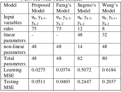
Table 2. Comparison of Proposed Neuro-Fuzzy Network with other Models
Model Proposed Model
Farag’s Model
Sugeno’s Model
Wang’s Model Input
variables
uk, yk-1,
yk-2
uk, yk-1,
yk-2
uk, yk-1,
yk-2
uk, yk-1,
yk-2
rules 75 75 12 8
linear parameters
- - 48 32
non-linear parameters
48 48 14 48
Total parameters
48 48 62 80
Learning MSE
0.0275 0.0374 0.5072 0.6184
Testing MSE
0.0511 0.0403 0.2447 0.2037
The proposed modelling model is compared with that of Farag’s [5], Sugeno’s [12] and Wang’s [13] approaches and the results are shown in table 2. The comparison shows that the proposed approach can be effectively applied for modelling of non-linear complex processes.
5.WATER BATH TEMPERATURE
CONTROL SYSTEM A. System
The neuro-fuzzy network proposed in section 2 is implemented as a controller for simulated water bath system. The mathematical model for a water bath system has been developed with the following
specifications: water tank capacity: 12 litres, inlet water: 25οC, base heater: 2500 watts, flow rate of water: 1 litre/min, sampling period: 30 seconds and system time delay: one sample.
The control objective is to regulate the temperature of water in tank. The process of water bath system can be represented by the equation given.
p i
C V
Q V
T T F
dt dT
ρ
+ −
= ( ) (9)
where T is tank temp., F is flow rate, Ti is inlet
temp., V is volume of the tank, Q is heat input, p
c
is specific gravity and ρis density. B. NFC implementation.The controller is implemented using the neuro-fuzzy network described in Section 2. It has two inputs e, and ce i.e. output error and change in error respectively, and a single output i.e. control signal; the heat input to the plant, Q. All input and output variables are partitioned into five fuzzy linguistic spaces {NL, NS, ZE, PS, PL}. The initial centers and widths of the 15 membership functions of input-output variables and the possible 125 rule combinations are chosen at random. The universe of discourse for all linguistic variables is uniformly chosen to be [-1.5, 1.5]. The inputs and outputs are scaled to restrict their value within the limits of the universe of discourse.
.
0 20 40 60 80 100 120 140 25
30 35 40 45 50
0 20 40 60 80 100 120 140 25
30 35 40 45
0 10 20 30 40 50 60 70 80 90 100 24
26 28 30 32 34 36 38 40 42
C. Results and Discussions
Three groups of simulation tests are conducted on water bath system to test the NFC’s adaptability to variation in set point, disturbances or delay [15]. In first set of simulations, the tracking performance of each controller with respect to set point changes is studied. A multi-step reference signal, 30οC, 40οC and 50οC for 40 samples each, is used. From figure 2, it is seen that FLC is able to track all three set points well but has larger rise time than the NFC controller.
The second set of simulation tests are used to study ability of the controllers in rejecting unwanted load disturbances. Impulse disturbances of values 4οC and -2οC are added to process output at the 50th and 90thsampling instants, respectively. A uniform set point of 40οC is given. From the results given in figure 2, it is observed that the FLC is slower in
0 20 40 60 80 100 120 140 25
30 35 40 45 50
0 20 40 60 80 100 120 140 25
30 35 40 45
0 10 20 30 40 50 60 70 80 90 100 24
26 28 30 32 34 36 38 40 42
rejecting disturbances.
Variable lag time is one of the common problems in controlling industrial processes. In the third set of simulation tests, artificial time delay of one sample is added to the system after 40th sample. Two set points 30οC between 0<t<40 and 40οC between 40<t<160 are given. From the results given in figure 2, it is very clear that NFC performs better and is able to track the set point well.
6. CONTINUALLY STIRRED TANK HEATER A. System
The continually stirred tank heater (CSTH) is one of the most commonly used process in chemical industry. In CSTH, the objective is to raise the temperature of the inlet stream to a desired value. A heat transfer fluid is circulated through a jacket to heat the fluid in tank. The equations used to model the system are [17]:
Sample number Sample number
T
an
k
T
em
p
(º
C)
T
an
k
T
em
p
(º
C)
T
an
k
T
em
p
(º
C)
T
an
k
T
em
p
(º
C)
T
an
k
T
em
p
(º
C)
T
a
n
k
T
e
m
p
(º
C)
Set point Tracking (a) NFC (b) FLC
(d) FLC Disturbance Rejection Test (c) NFC
[image:5.595.89.468.127.519.2]Variable Delay Test (e) NFC (f) FLC
0 100 200 300 400 500 600 700 35
40 45 50 55
0 100 200 300 400 500 600 700
35 40 45 50
0 50 100 150 200 250 300 350 400 450 35
40 45 50
p j i
C V
T) UA (T
V -T) F(T dt dT
ρ
− +
= (10)
pj j j
j
j j ji j j
C V
T) UA (T
V ) T (T F
dt dT
ρ
− −
−
= (11)
where, T and Tj are output temperatures, F and Fj
are flow rates, Ti and Tji are inlet temperatures,
Cp and Cpj are heat capacities, ρ and ρj are fluid
density, V and Vjare volumes for tank and jacket
respectively. U is overall heat transfer coefficient and A is area for heat transfer.
B. NFC implementation.
The controller is designed using the neuro-fuzzy network described in Section 2. For simplicity, only one output, the tank temperature is considered. The controller has two inputs e, and ce, error and change in error in the plant output and a single
0 100 200 300 400 500 600 700
35 40 45 50 55
0 100 200 300 400 500 600 700
35 40 45 50
0 50 100 150 200 250 300 350 400 450 35
40 45 50
control signal output Fj, the jacket flow rate. The
type and number of parameters are chosen similar to those taken for the water bath temperature control system. All input and output variables are partitioned into five fuzzy linguistic spaces. The inputs and outputs are scaled so that they do not exceed the limits of the universe of discourse. For the NFC implementation, evaluation routine given in Section 4 is followed. A multi-step reference signal, T=50οCand Tj=70οC, T=55οC
and Tj=80οC and T=40οC and Tj=50οC for 200
samples each is used. The GA is used to tune the 25 rules and the 30 input-output membership functions parameters in 89 generations. Refer table 1 for details. Identical parameters are taken for FLC and the NFC. The values of the three scale factors, GE, GC and GU are (0.032, 0.28, 4.0) for transient state
Sample number Sample number
T
an
k
T
em
p
(º
C)
T
an
k
T
em
p
(º
C)
T
an
k
T
em
p
(º
C
)
T
an
k
T
em
p
(º
C)
T
a
n
k
T
e
m
p
(º
C)
T
an
k
T
em
p
(º
C)
Set point Tracking (a) NFC (b) FLC
(d) FLC
[image:6.595.92.499.109.520.2](f) FLC Disturbance Rejection Test (c) NFC
Figure 3. Performance tests for Neuro-Fuzzy Controller (NFC) and Fuzzy Controller (FLC) for Continually Stirred Tank Heater Temperature Control System
and (0.6, 4.0, 0.085) for the steady states of the multi step reference signal.
C. Results and Discussions
For each controller, three simulation tests similar to those performed for water bath system are conducted. In the first test (tracking performance test), a multi-step reference signal, T=50οC & Tj=70οC, T=55οC & Tj=80οC and T=40οC&
Tj=50οCfor 200 samples each is used. For second
set of tests (disturbance rejection), impulse load disturbances of values -2οCand 5οCare added to the output tank temperature at the 200th and 400th sampling instants, respectively. The two-step reference signal, T=50οC& Tj=70οCand
T=40οC& Tj=50οCfor 300 samples each is used.
In the third set of tests the inherent one sample delay in the system is increased to two samples for first 200 samples and further increased to three samples after the 200thsample. In these simulation experiments two set points T=50οC& Tj=70οC,
and T=40οC& Tj=50οCfor 200 samples each are
given.
The results are plotted in figure 3. It is observed although set-point tracking and disturbance rejection tests show similar performance for the two controllers, NFC performs better for the variable delay test. In NFC, the oscillations in the output response due to the increase in the delay times are far less in magnitude than in FLC.
7. CONCLUSIONS
The major advantage of the method developed is that all parameters of the neuro-fuzzy network including the rule base are tuned simultaneously. The initial GA populations for simulated problems are randomized, which implies that minimum heuristic control knowledge is used. The neuro-fuzzy approach is implemented on a well known numerical example derived from literature and two chemical processes used widely in the industry. The performance of the NFC designed using the proposed approach is compared with other existing approaches. The results confirm that the methodology used in the NFN can be effectively used to build accurate linguistic neuro-fuzzy models and competes well with other existing approaches.
REFERENCES
[1] H. R. Berenji, “Learning and Tuning Fuzzy Logic Controllers Through Reinforcements”, IEEE Transactions on Neural Networks, Vol. 3, 1992, pp. 724-740.
[2] J. R .Jang, “Self-learning Fuzzy Controllers Based on Temporal Backpropagation”, IEEE Transactions on Neural Networks, Vol. 3, 1992, pp. 714-721.
[3] C. L. Karr and E. J. Gentry, “Fuzzy Control of pH Using Genetic Algorithms”, IEEE Transactions on Fuzzy Systems, Vol. 1, 1993, pp. 46-53. [4] A. Varsek, T. Urbancic, and B. Filipic, “Genetic Algorithms in Controller Design and Tuning”, IEEE Transactions on Systems, Man & Cybernetics, Vol. 23, 1993.
[5] W. A. Farag, V. H. Quintana, and G. Lambert-Torres, “A Genetic-Based Neuro-Fuzzy Approach for Modelling and Control of Dynamical Systems”, IEEE Transactions on Neural Networks, Vol. 9, No. 5, 1998, pp. 756-767.
[6] M. Lee and H. Takagi, “Integrated Design stages of Fuzzy Systems Using Genetic Algorithms”, in Proc. FUZZ-IEEE’93, San Fancisco CA, 1993, pp. 612-617.
[7] K. Shimojima, T. Fukuda, and Y. Hasegawa, “Self-tuning Fuzzy Modelling with Adaptive Membership Function, Rules, and Hierarchical Structure Based on Genetic Algorithm”, Fuzzy Sets and Systems, Vol. 71, 1995, pp. 295-309.
[8] T. L. Seng, M. B. Khalid, and R. Yusof, “Tuning of a Neuro-Fuzzy Controller by Genetic Algorithm”, IEEE Transactions on Systems, Man & Cybernetics, Vol. 29, 1999, pp. 226-236.
[9] K. S. Narendra and K. Parthasarathy, “Identification and Control of Dynamical Systems Using Neural Networks”, IEEE Transactions on Neural Networks, Vol. 1, No. 1, 1990, pp. 4-27. [10] C. T. Lin and C. S. G. Lee, “Neural Network Based Fuzzy Logic Control and Decision System”, IEEE Transactions on Computer., Vol. 40, 1991, pp. 1320-1336.
[11] A. Homaifar and E. Mccormick, “Simultaneous Design of Membership Functions and Rule Sets for Fuzzy Controllers Using Genetic Algorithms”, IEEE Transactions on Fuzzy Systems, Vol. 3, 1995.
[12] T. Takagi and M. Sugeno, “Fuzzy Identification of Systems and Its Applications to Modelling and Control”, IEEE Transactions on Systems, Man & Cybernetics, Vol. 15, 1985. [13] L. Wang and R. Langari, “Complex Systems Modelling via Fuzzy Logic”, IEEE Transactions on Systems, Man & Cybernetics, Vol. 26, 1996, pp. 100-106.
[14]Han-Xiong Li and H. B. Gatland, “A New Methodology for Designing a Fuzzy Logic Controller”, IEEE Transactions on Systems, Man and Cybernetics, Vol. 25, No. 3, 1995, pp. 505-512. [15] M. Khalid, S. Omato and R. Yusof, “Temperature Regulation with Neural Networks and Alternative Control Schemes”, IEEE Transactions on Neural Networks, Vol. 6, No. 3, 1995, pp. 572-582.
[16] B. W. Bequette, Process Dynamics – Modelling, Analysis and Simulation, Prentice Hall PTR, 1998.
[17] M. Hassoun, Fundamentals of Artificial Neural Networks, Prentice Hall India, 1998.