UNIVERSIDAD DE VALLADOLID
ESCUELA DE INGENIERIAS INDUSTRIALES
Grado en Ingeniería Mecánica.
Diseño de los estabilizadores verticales y
horizontales de un vehículo aéreo no
tripulado (UAV)
Autor:
Pablo Marcos García
Responsable del intercambio:
Marta Herráez Sánchez
Universidad de Destino:
Valladolid, Julio, 2017.
TFG REALIZADO EN PROGRAMA DE INTERCAMBIO
TÍTULO: Design of of HALE-UAV vertical and horizontal stabilizer
ALUMNO: Pablo Marcos García
FECHA: 07/06/2017
CENTRO: Faculty of Mechanics – Vilnius Gediminas Technical University
Index
LIST OF FIGURES ... 8
LIST OF TABLES ... 10
LIST OF GRAPHICS ... 11
GLOSSARY ... 12
Symbols ... 12
Acronyms ... 12
1. Preface ... 13
1.1. Introduction ... 13
1.1.1. HALE-UAV ... 13
1.1.2. Design Phases ... 16
1.2. Motivation ... 19
1.3. Objective ... 19
1.4. Initial statements and values ... 20
1.5. Essential concepts about aerodynamics ... 21
1.6. Conditions at different altitudes ... 22
2. Tail design ... 25
2.1. Horizontal tail design ... 25
2.2. Vertical tail design ... 32
2.3. Tail control surfaces ... 35
2.3.1. Elevator design ... 35
2.3.2. Rudder design ... 42
3. Operations, results and analysis ... 45
3.1. Calculations (MATLAB programing) ... 45
3.1.1. Programs ... 45
3.1.2. Solutions ... 65
3.2. 3D design (CATIA) ... 70
3.3. Flow analysis (SolidWorks) ... 75
3.4.1. Horizontal ribs ... 80
3.4.2. Horizontal longeron ... 81
3.4.3. Vertical ribs ... 83
3.4.4. Vertical longeron ... 85
4. Description of control system ... 87
5. Determination of the requirements of safety work using the device ... 89
6. Environmental requirements ... 95
6.1. Population and social aspects ... 95
6.2. Flora and fauna ... 95
6.3. Soil and landscape ... 96
6.4. Surface and ground water ... 96
6.5. Impacts on air and climate change ... 96
6.6. Immovable and cultural heritage ... 97
7. Economical calculations ... 98
Prices List ... 99
Break-even point calculation ... 102
8. Conclusions ... 104
List of references ... 106
LIST OF FIGURES
Figure 1.1.- cloud seed and 3D mapping. ... 13
Figure 1.2.- Aircraft forces. ... 21
Figure 2.1.-Aircraft tail basic tail configuration [29]. ... 26
Figure 2.2.- AFT configurations [29]. ... 26
Figure 2.4.- Airfoil Graphics [39]. ... 29
Figure 2.3.- N.A.C.A. airfoils [29]. ... 30
Figure 2.5.- Horizontal tail and elevator geometry [29]. ... 36
Figure 2.6.- control surface to control chord ratio ... 39
Figure 2.8.- Different combined turn. ... 42
Figure 2.9.- Vertical tail and rudder geometry for a swept rudder (left) and for a rectangular rudder (right) [29]. ... 42
Figure 2.10.- Rudder deflection representation. ... 44
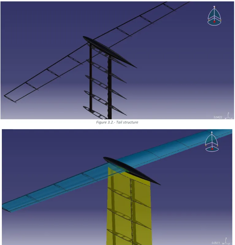
Figure 3.1.- Tail structure. ... 70
Figure 3.2.- Tail structure ... 70
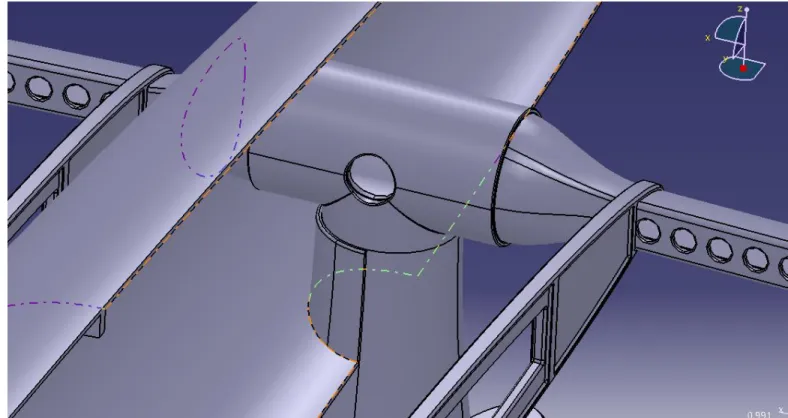
Figure 3.3.- join between vertical and horizontal longeron and the tear shape ... 71
Figure 3.4.- Rear longeron ... 72
Figure 3.5.- Hinge and rear longeron detail. ... 72
Figure 3.6.- Interior and exterior of the tear shape ... 73
Figure 3.7.-Selected motor [59]. ... 73
Figure 3.8.- Designed gears. ... 74
Figure 3.9.- Flow mesh. ... 75
Figure 3.10.- Tear shape flow definition. ... 76
Figure 3.11.- Steam flow lines. ... 76
Figure 3.12.- XY Plane speed diagram. ... 77
Figure 3.13.- XY plane speed diagram. ... 77
Figure 3.14.- the top one is the flow pressure around the tail and the bottom one is the pressure on the tail surfaces. ... 78
Figure 3.15.- vorticity diagrams. ... 79
Figure 3.16.- analysis solutions. ... 79
Figure 3.18.- Horizontal rib stress analysis. ... 80
Figure 3.19.- Horizontal rib deformation analysis. ... 81
Figure 3.20.- Horizontal longeron bonundray conditions. ... 81
Figure 3.21.- Horizontal longron stress analysis. ... 82
Figure 3.22.- Detailed horizontal longeron stress analysis. ... 82
Figure 3.23.- Horizontal longeron deformation analysis. ... 83
Figure 3.24.- Vertical rib boundary conditions. ... 83
Figure 3.25.- Vertical rib stress analysis. ... 84
Figure 3.26.- Vertical rib deformation analysis. ... 84
Figure 3.27.- Vertical longeron boundary condition. ... 85
Figure 3.28.- Vertical longeron stress analysis. ... 85
Figure 3.29.- Vertical longeron deformation analysis. ... 86
Figure 4.1.- Control scheme ... 87
LIST OF TABLES
Table 2.1.- Horizontal and vertical volume coefficient for different aircrafts [29]. ... 28
Table 2.2.-Angular Acceleration about main gear for different types of aircrafts. ... 37
Table 2.3.- Estimation parameters for Inertia estimation ... 39
Table 2.4.- Design requirements. ... 43
Table 5.1.- Table of risk level depending in severity and probability ... 90
Table 7.1.-Structural raw material cost. ... 99
Table 7.2.- Devices cost. ... 100
Table 7.3.- Molds cost. ... 100
Table 7.3.- Employees cost. ... 101
Table 7.5.- Cost splitted by parts... 102
LIST OF GRAPHICS
Graphic 2.1.-Deflection need - Aircraft Speed. ... 40
Graphic 2.2.- Lift distribution for the UAV horizontal tail. ... 41
Graphic 7.2.- Percentage of cost for a unit. ... 103
GLOSSARY
Symbols
WTO: Aircraft maximum takeoff weight [N]
m: mass [kg]
S: Reference area [m2]
g: Gravity [m/s2] T: Temperature [K]
P: Pressure [Pa]
ρ: Density [kg/m3]
μ: Dynamic viscosity [kg /m·s]
AR: Aspect Ratio [-]
λ
: Taper Ratio [ º]CRoot: Root Chord [m]
CTip: Tip Chord [m]
b: wingspan [m]
αT: Twist angle [º]
Λ: Sweep angle [º]
Γ: Dihedral angle [º]
α
a: Angle
of attack at takeoff [º]α
c: A
ngle at cruise speed [º]Cl: airfoil lift coefficient [-]
Cd: airfoil drag coefficient [-]
Cm: airfoil pitching moment coefficient [-]
V: Volume coefficient [-]
Acronyms
HALE: High-Altitude Long Endurance
UAV: Unmanned Aerial Vehicle
CAD: Computer Aided Design.
ISA: International Standard Atmosphere
1.
Preface
1.1.
Introduction
One of the biggest part of this planet is the atmosphere in which can be done a lot of
things, since investigation to surveillance; but normally, to do this kind of operations is needed
a manned aircraft, probe-balloons with non-recoverable material or drones that cannot
exceed low altitude. For this reason, is very interesting to develop a new kind of aircraft,
environmental-friendly and unmanned to allow the scientist to investigate, monitoring the
ozone in the atmosphere, to use them as atmosphere satellites for communication or even 3D
mapping, or to enable countries with poor rain do the “cloudseeds”.
Is important to denote other similar aircrafts and the design phases for this plane.
1.1.1.
HALE-UAV
1.1.1.1. HALE
HALE is the acronym for High Altitude Long Endurance. This kind of aircrafts can reach
the stratosphere without landing for considerable periods of time.
The very first time when an article about long endurance was published was on 1984
when M.D. Maughmer (University Pennsylvania State) and D.M. Somers (NASA Langley)
Design and experimental results for a high-altitude, long-endurance airfoil. Then interest of
weather data and obtain information about cruise missiles. Due to this first concept and the
objectives that aim for, the following researches were in direction of develop a sneaky military
aircraft for surveillance and for obtaining information.
The tropopause is the borderline between the troposphere and the stratosphere; it’s
located in average at 13000 meters. At this point the temperature is almost constant but very
low, and the sun irradiance gets higher due to the lack of clouds. Due to these conditions is
necessary to solve the problems as frozen wings, frozen motors, frozen telemetry
components, communication problems, etc. The possible solutions adopted to overpass these
issues will be commented ahead.
1.1.1.2. UAV
UAV is the acronym for Unmanned Aerial Vehicle, are aircrafts that without a human
pilot abroad that allows these planes to control the flight and the operation from a station.
Most of this kind of aircrafts are the common drones that nowadays are all around,
that enable the developing of new sensors and structures to improve the most autonomous
flight.
Today we have drones for civil and transport uses but it was conceiving as a military
aircraft. Due to this, when the people talk about UAV or HALE or the combination of both is
not hard to think about a military aircraft. This thought is changing with the time and
developing non-military planes. As this is changing more and more companies can bet in the
develop of this technology as could be DJI or Syma.
As well, drones are used in very beneficial cases as firefighting, events surveillance,
danger spots surveillance, unsafety places recognition and so on.
1.1.1.3. Combination of both technologies
The combination of these two meanings gives an aircraft capable of do some complex
operations that manned aircraft cannot do. This kind of aircrafts are provided with sensors,
actuators, tools, software, computing technology and real-time communications systems that
let the “pilots” do them work as they are in the aircraft. Furthermore, these elements enable
the aircraft to do any operation for which it is intended.
This kind of aircrafts can do either the function of a drone and a GPS as could be from
surveillance, recognition, collecting data of big portions of land, weather information to
positioning monitoring to drive autonomic cars or communications repeater.
As seen before, the most of these drones have military proposals as could be the
RQ-4 Global Hawk, but here are also non-military ones as could be Airbus Zephyr which is designed
for observation and communications relay.
For these planes 2 technologies are used:
- Solar powered: It have the advantage at high altitude there are not any cloud that
could reduce the solar irradiation over the solar panels and the solar energy never
ends. The contras of this type of aircrafts are the complex design of the wings and
the battery weight due to the need to be able to fly at night and have enough power
to do it.
- Liquid-hydrogen powered: This kind of fuel enable the plane to be sneaky due to
the exhaust gases are no as heat as a jet-motor could expulse, and the structure is
not so complex and big as a solar powered UAV. The contras of this type of design
is the limited fuel and build a space to keep it and, also, the change of the gravity
center.
- Nuclear powered: There are no UAV with this technology but there are some
investigations that aim to reach this point. This would have the advantage of enable
the aircraft to do almost global operations from where it is launched without any
steam (allows even more stealth) but with the disadvantages of nuclear power.
1.1.2.
Design Phases
For design an aircraft, firstly, is needed to design the wings especially for this aircraft
in which the wing design is crucial to obtain power for the batterie. Moreover, is important to
To design a wing the first step should be decide the position of the wing; it could be
low wing, high wing, mid wing or parasol wing.
The selection of the position of the wing depends on the requirements. For the UAV in
this project the most important requirement is the stability, then the selected wing is a high
wing to do not compromise the drag coefficient.
After this, is needed to select the airfoil. This step is very critical since in this element
depends the aircraft lift. Depending in the shape of the airfoil and in the angle of attack will
be a different lift, drag and pitch, which is very important for the aircraft stability. Figure 1-5.- Position of the wing [29].
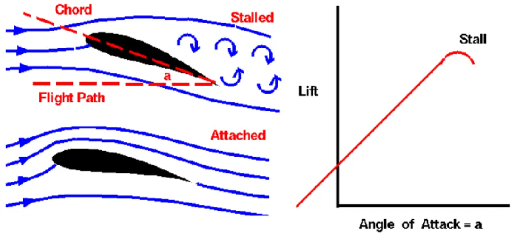
The lift will depend on the airfoil and on the angle of attack of the airfoil being higher
in the taking off operation to have a higher lift and make the plane climb up. This operation
must be done carefully because there is a point, called stall point, or stall angle, where the
drag force is greater than the lift force and make the wing to stall, to do not generate enough
lift force to stay in the air.
Next step should be choosing the right parameters for sweep and dihedral angles that
provides the aircraft more stability. Sweep angle makes the with not to have compression
phenomena at the leading edge of the wing, especially in supersonic planes, meanwhile the
dihedral angle improves the roll stability increasing the angle of attack (and the lift) on the
downer wing if the aircraft starts to roll.
Then, the designer should calculate other parameters as aspect ratio, incidence angle
or set angle or the taper ratio.
Last step is to compare the results from the wing designed and the requirements and
decide if the wing fix them or not. If not, is necessary to repeat the steps above until the
requirements are satisfied and optimize the wing.
Figure 1-7.- Angle of attack effect on an airfoil
After this, the second phase, is to design the body. At this point is important to design
a body that do not create a lot of drag and have enough space for all the elements for the
control and to carry out the operations. Also, it has the undercarriage to enable a safety
landing. With all this, the body must be the lightest possible to allow the plane to fly easy.
Finally, the last phase is to design the tail, the stabilizators (vertical and horizontal), the
elevators and the rudder. This part fixes all imbalances that can be caused by the irregular
distribution of forces along the body and trim the aircraft balance in every part of the flight
mission. This part helps to pitch and yaw the aircraft if it haves to change the direction. The
design steps will be described later.
1.2.
Motivation
The motivation on this project is to improve the air-crafting knowledge dealing to the
lack of knowledge in one field and solve that problem using the technology.
This work is a very good opportunity to improve my computer skills as well, using
programs as MATLAB to improve the knowledge about such programming language; CATIA,
using all what I have learned in the university about this program; SolidWorks learning how to
use it and its possibilities.
1.3.
Objective
The objective is to design a suitable aircraft with which is possible to resolve all the
problems in the way of the final concept. Is a good way to feel like in a company when a new
problem is proposed and the team should work in the same way to achieve the best result,
dealing one with each other and sharing ideas.
1.4.
Initial statements and values
The very first statement is that this is an early concept about the design of the
HALE-UAV, so all parameters could be improved in a future work.
WING-SPAN 25.7 (m)
MAC 1.32 (m)
SURFACE 38 (m^2)
AR 17.4
ROOT CHORD 1.8 (m)
WEIGHT OF EACH MOTOR 3.2 (kg)
SOLAR PANEL WEIGHT 4.03 kg
WING STRUCTURE WEIGHT Máx. 8 (kg)
STALL SPEED 4.065 (m/s)
CRUISE SPEED 16.7 (m/s)
ATTACK ANGLE AT TAKING OFF 8 (º)
CRUISE ATTACK ANGLE 2 (º)
CRUISE HIGH 10-17 (km)
LIFT COEFFICENT AT TAKING OFF (Cl) 1.2
CRUISE LIFT COEFFICENT (Cl) 0.65
PITCH MOMENT (Cm) TAKE OFF -0.085
PITCH MOMENT (Cm) CRUISE -0.105
DRAG COEFFICENT (Cd) 0.04-0.02
FUSELAGE ANGLE AT TAKING-OFF 8º
FUSELAGE ANGLE AT CRUISE OPERATION 0 (º)
MAXIMUM FUSELAGE DIAMETRE 1.2 (m)
MAXIMUM FUSELAGE HEIGHT 3.5 (m)
TAPER RATIO 0.75
AIRCRAFT WEIGHT 50 (Kg)
GRAVITY CENTER POSITION FROM THE AIRCRAFT COMMENCEMENT 3.3 (m)
ZERO LIFT WING ANGLE OF ATTACK 3.6 (º)
STALL ANGLE 12 (º)
DISTANCE BETWEEN MOTORS 12.750 (m)
DISTANCE FROM THE AIRCRAFT COMMENCEMENT TO THE MAIN WHEEL 3.5 (m)
POSITION (X, Z) OF THE GRAVITY CENTER (3.3,0.6) (m)
1.5.
Essential concepts about aerodynamics
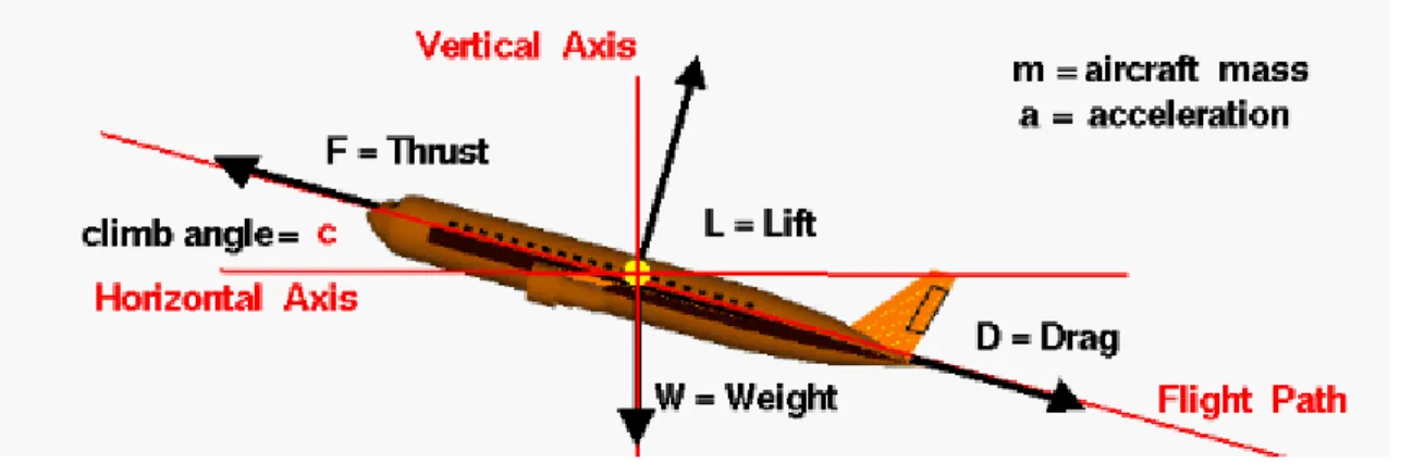
Is needed that an aircraft lifts its own weight and payload weight and fly at a
determinate speed. To enable this is necessary that the plane overcome the gravity or the
weight force, and the drag force:
• Lift: Is the force generate by the difference of pressure originated by the asymmetry in the wing direction of an airfoil what makes the wind go faster by one
face than the other. This parameter depends on the airfoil shape, airfoil-air relative
speed, density and angle of attack. For simplify this force is said that it acts by a
point called the center of pressure.
• Thrust: Is the force originated by the motor and which allows the aircraft to move forward (and sometimes backwards or to brake). The direction of this force
depends on the position of the motors relative to the aircraft and the magnitude
depends on the motor-group power; as well depends on density and propeller
shapes.
• Weight: Is the opposite force at lift and it is created by the aircraft mass and the gravity attraction. As well, to simplify this force it is said that it operates through
the center of gravity.
• Drag: this is the opposite force at thrust and it makes the aircraft to need more energy that it would need. This force is always when there are movement and it
goes in the opposite way. It depends mainly in the speed, density and viscosity but
in the shape of the UAV too.
1.6.
Conditions at different altitudes
Due to this aircraft’s operations, it needs to overcome different conditions at different
altitudes and be stable in all of them so they are showed up here:
• Gravity: The force between 2 bodies are weaker as the bodies are getting separated from each other, so when the UAV is climbing the force that makes the
plane return to earth is less strong.
• Temperature: The temperature goes down while the aircraft is climbing until it arrives the tropopause, located at 11000-13000 m more or less, where the
temperature keeps stable.
• Pressure: As there are less air mass above, the atmospheric pressure is less as the plane climb.
• Density: Taking the air as an ideal gas, is possible to relate the temperature and the pressure to the air mass and the volume it occupies, or in other words is
possible to relate the pressure, the temperature and the density of the air.
• Viscosity: It goes down as the aircraft climb due to the decrement on the temperature.
Thanks to previous calculation in the other components of the aircraft is possible to
plot the different variations as follows:
R² = 1
9,200 9,300 9,400 9,500 9,600 9,700 9,800 9,900
0 2000 4000 6000 8000 10000 12000 14000 16000 18000
R² = 0,9987
150 170 190 210 230 250 270 290
0 2000 4000 6000 8000 10000 12000 14000 16000 18000
T
[K
]
Altitude [m]
T [K] vs Altitude [m ]
R² = 0,9997
0,0E+00 2,0E+04 4,0E+04 6,0E+04 8,0E+04 1,0E+05 1,2E+05
0 2000 4000 6000 8000 10000 12000 14000 16000 18000
0,0000 0,2000 0,4000 0,6000 0,8000 1,0000 1,2000 1,4000
0 2000 4000 6000 8000 10000 12000 14000 16000 18000
Air Density [kg/m
3] vs Altitude [m]
1,00E-05 1,10E-05 1,20E-05 1,30E-05 1,40E-05 1,50E-05 1,60E-05 1,70E-05 1,80E-05
2.
Tail design
As is showed before, the tail has 2 main surfaces, horizontal and vertical. The steps for
design them are different so the following lines describes how to design them for the solar
powered UAV-HALE in this document, the decisions selected and the advantages and
disadvantages from each decision.
2.1.
Horizontal tail design
The main phases to design a vertical tail or a horizontal tail are different but the first step
for both are the same.
First is required to select the main requirements for our tail should satisfied for our
aircraft. The list of design requirements that must be considered and satisfied in the selection
of tail configurations for an UAV-HALE is as follows [29]:
1. Longitudinal trim.
2. Directional trim.
3. Lateral trim.
4. Longitudinal stability.
5. Directional stability.
6. Lateral stability.
7. Manufacturability and controllability.
8. Operational requirements.
9. Airworthiness (e.g. safety, tail stall, and deep stall).
10. Survivability (e.g. spin recovery).
11. Cost.
12. Competitiveness (Or economically feasible).
The tail configurations that satisfied the general requirements are like follow:
Due to simplicity, effectiveness and cost, an aft tail and one vertical tail configuration is
selected for our UAV. Is important to denote that, for the same requirements, not only one
vertical configuration satisfied the requirements so the tail configuration depends mainly on
designer’s choice.
Once the tail configuration has been chosen as aft, is needed to select an aft
configuration. This tail configurations are as follow:
Figure 2.1.-Aircraft tail basic tail configuration [29].
A T-tail configuration is selected for our UAV due to the advantages that this configuration
provides. In the searching for the most stable aircraft this configuration is out of the regions
the wing creates as wing wake, wing downwash, wing vortices, and motor turbulence flow.
This make to the horizontal tail have more efficiency and safer structure, that mean a smaller
horizontal area and less tail vibration and buffet. Whit this configuration the vertical tail is out
of the horizontal tail wing wake region and out of end-plate effect then it results in smaller
vertical area too.
In the other hand, there 2 important disadvantages. These disadvantages are: heavier
vertical tail since it should have the required structure to support the horizontal tail and the
elements to control the moving surfaces; the other drawback is the deep stall, this is a critical
situation where the wing and the horizontal tail are stalled and the horizontal tail and the
elevator have reduced their efficiency that make the plane lock in the deep stall with not
possibility of go out of that situation. To avoid the deep stall in a T-tail configuration is needed
to ensure a stable pitch at the initial stall; extend the horizontal tail span substantially beyond the
motor; or/and employ a mechanism to enable full down elevator angles if a deep stall occurs to
make able to take out the plane from that situation.
The following step is to calculate the optimum horizontal arm to trim the aircraft horizontal
stabilization. The horizontal arm serves as the arm for the tail pitching moment about aircraft cg
to maintain the longitudinal trim. The trim depends on 2 parameters, the arm and the horizontal
surface; when the first raises the second must decrease and if the first decrease the second must
rise. So, the calculation is to have the optimum arm with the optimum surface that do not generate
so much drag and do not weight much. The formula to calculate it is the following one:
Where Kc is a correction factor for the aft portion of the fuselage which tend to be 1 for
our aircraft for have cylindrical-conical shape, 𝐶̅ is the wing main chord, S is the wing surface,
Df is the maximum diameter of the fuselage and 𝑉̅̅̅𝐻 is the horizontal volume coefficient which
for a first approximation of the horizontal tail arm is needed to take it from the following table:
This UAV is similar to a motor glider then a value of 0.6 is chosen for the horizontal tail
volume coefficient. The result of this operation gives 6.19 m in the first iteration but there are
some longitudinal size requirements and doing some iterations with the body project and its
requirements the final value was fixed on 5.98m; that maybe makes the tail heavier and the
surface bigger and it makes the plane less manageable or quick in the moves, anyway is the
optimum arm.
The following step is to calculate the horizontal platform by the following equation:
𝑉̅
𝐻=
𝑙 𝑆
ℎ𝑆 𝐶̅
→ 𝑆
ℎ=
𝑆 𝐶̅ 𝑉
̅
𝐻𝑙
And the wing-fuselage pitching coefficient that provides a measure of how feasible the
aircraft to climb or go down:
Where 𝐶𝑚𝑎𝑓 is the wing airfoil section pitching moment coefficient, AR the wing aspect
ratio, Λ the wing sweep angle and αtwist is the wing twist angle.
Table 2.1.- Horizontal and vertical volume coefficient for different aircrafts [29].
Equation 2.2
The values obtained for these parameters are Sh = 5.64 m2 and Cmwf = -0.09 which means that the aircraft on its own goes down.
And is needed to calculate the wing-fuselage lift cruise coefficient as:
The result for this parameter is CL = 0.65.
With these parameters is able to calculate the desired lift coefficient for the horizontal
tail as follow:
That result in a value of CLh = -0.33 and a maximum lift coefficient for the horizontal tail
of CLh max = 0.91.
By the result in this equation we can decide the horizontal tail airfoil. Is decided to select
a symmetrical N.A.C.A. airfoil so the following graph can help about the selection of the correct
airfoil:
Equation 2.4
Equation 2.5
With the parameters obtained before, is decided to select the N.A.C.A. 64-008A with a
thickness about 8% being a symmetric airfoil, so, with no angle of attack it would generate
zero lift. This airfoil has the following parameters:
This graphics gives important information about the airfoil as the airfoil lift curve slope
which is 6.3 rad-1. A symmetric airfoil is perfect for a horizontal airfoil since changing the shape with the elevator It can generate lift force upwards or downwards depending in the real-time
requirements.
Once the airfoil is selected is needed to choose the following parameters: Sweep and
dihedral angle, which in this case, for this aircraft I would be 0 deg. for both due to simplicity
and not need to include this kind of angles in the horizontal tail. Tail aspect ratio which it
would be two thirds of the wing aspect ratio and the taper ratio which is chosen to be the
same as the wing taper ratio and it is 0.75.
With the all the parameters of the horizontal tail could be calculated the horizontal tail
lift curve slope which will help to calculate the needed fix angle for the horizontal tail. In this
case, the lift curve slope result in 5.37 rad-1.
Knowing the cruise parameters can be calculated the angle of attack of the horizontal
airfoil during the cruise operation due this part of the flight is the main part. Furthermore, in
this case, being a T-tail, and being out of the wing downwash region, this angle will be the fix
angle too. For this aircraft, the value would be -0.06 deg. The way to calculate it is by this
equation:
It is usual that the longitudinal trim required a negative angle at the horizontal tail, so is
possible to see that the parameters that are appearing have sense. Nevertheless, this valor is
not the result of just one operation, is the result of an iteration until the lift coefficient
resulting of calculate the result backwards is similar to the desired one.
The final step to determine in the main horizontal surface are the geometrical
parameters, to calculate them is necessary to resolve a non-linear system of 4 equations with
4 roots:
Equation 2.6
Solving this system with a mathematical program the following value are reached: the
horizontal wing span should be 8.09 m long; the main chords is 0.70 m while the chords at the
root is 0.79 m and at the tip is 0.59 m long.
What remains to be done in this surface is to check if the horizontal static stability and
the horizontal wing optimization. To perform the first one the result of the following operation
should be negative:
In the present case, the resulting value is -3.29 that means that the aircraft is strongly
stable at cruise operation. Must be mentioned that in more advance design stage, with other
aircraft parameters obtained such inertias or aerodynamic derivates, it would be necessary to
perform a dynamic stability study based on one dumped oscillatory mode and two
exponentials models to control the Dutch Roll mode, the Rolling mode and the Spiral mode.
For this very early stage at the design process and with such raw objective is obviate this study
and assumed as this model is dynamic stable as it is static stable.
The optimization at the initial values from the other parts has been done meanwhile the
calculations has been resolved. To do some better optimization about all the parts is necessary
an iterative process between all the parts and years of work so, once again, in this early stage
of the process there is no point to do something like that.
In the case that some of the requirements are not satisfied, is necessary to go backwards
in earlier steps of the design and change some parameters until the requirements are satisfied.
2.2.
Vertical tail design
As seen in the previous headland once the tail configuration is chosen, is necessary to
select the vertical tail volume coefficient, which for this UAV is selected to be 0.03 in this early
study based in other aircrafts, as well, due to the same reason, the vertical optimum arm is
designated to be the same as the horizontal optimum arm.
Once that values are known is easy to calculate the necessary vertical tail surface:
Which result for the aircraft in this project is 4.90 m2 which means a really big vertical tail but is normal if the tail arm is reduced from the optimal one due to longitudinal constrains, so
for the same spin with less arm is need a greater force supply with a greater surface.
The following parameters for an early concept of an aircraft are based on other similar
planes. There is no information about HALE or solar-powered aircrafts by this reason the
parameters are selected similar to gliders, light air-crafting and aircrafts that prioritize
management than stability. Then the values acquired are as following:
Same airfoil section as the horizontal tail for simplicity since the horizontal airfoil is
symmetrical and such that is required for a symmetrical aircraft about the xz plane due the
plane is already trimmed and it do not need any lateral force. The vertical lift is needed in case
of non-symmetrical aircraft or twin vertical tails used on stealth air-crafting.
Vertical aspect ratio ARv = 1.33. The value of the vertical aspect ratio should be high to
improve the directional control and reduce the vertical chord needed, but a high vertical
aspect ratio for a T-tail derives in structural problems and heavier tail, also deteriorate the
lateral control due to the inertia in the y axis is greater. High value makes the aircraft
longitudinally unstable due to the greater weight origin on the aircraft a nose-up pitching. If
the aircraft has a T-tail configuration, the horizontal tail location and efficiency are functions
of vertical tail aspect ratio. Then, if the deep stall is critical, the vertical aspect ratio must be
large enough to keep the horizontal tail out of the wing wake when the wing stalls. Finally, as
greater the aspect ratio is, better is the aerodynamic efficiency and better is the dictional
stability due to bigger yawing arm. For a starting point and based on similar light aircrafts with
T-tail configuration the value above is selected.
Vertical taper ratio λv = 0.9. The main purpose to have a bigger chord at the root respect
the tip is to have a more stable structure reducing the bending stress at the root and this allow
the vertical tail to have sweep angle, but the things that brings are mainly bad parameters; an
increment in the taper ratio reduce the directional control due to the reduction of the yawing
moment arm and, also, reduces the lateral stability.
Vertical sweep angle Λv = 10º. When the sweep angle is increased the directional control
of the aircraft is improved but the directional stability is deteriorated and is decided to have a
bit of more control of the aircraft because there are just two control surfaces, even when the
stability is the primary factor. The sweep angle in a T-tail configuration improves the
longitudinal stability and control thanks to an increase of the horizontal tail moment arm.
The incidence angle and the dihedral angle are both 0º because this UAV have a
symmetrical airfoil with just one vertical tail configuration that do not allow the vertical tail to
have any lift force at cruise operations for do not compromise the directional stability.
Once these parameters are chosen, the following step is to calculate four geometrical
parameters at the same time to enable the construction. These parameters are calculated as
following:
With the values of this parameters it can be designed the vertical tail. Solving these
equations yields the following results: vertical tail spam (bv): 2.55 m; Vertical Main
Aerodynamic Chord (𝐶̅̅̅𝑣): 1.92 m; Root chord (CVRoot): 2.02 m; Tip chord (CVTip): 1.82m. This
shows that a big vertical tail is needed as we show with the area, and we can ascertain that it
is not a rectangular wing.
As in the horizontal tail, the last step in the vertical tail is to check the lateral stability in
case it generates lift forces that can untrimmed the lateral stability of the aircraft; and to
optimize the surface and the structure of the vertical tail.
Equation 2.15 Equation 2.13 Equation 2.14
Also, as was presented in the horizontal tail design explanation, this is a very early stage
of aircraft design and this is the result of just few iterations with the other parts. A better
improvement is possible changing the values chosen at the beginning and obtaining the best
with try and failure optimization.
As well, in the case that some of the requirements are not satisfied, is necessary to go
backwards in earlier steps of the vertical tail design, or even wing or fuselage design, and
change some parameters until the requirements are satisfied.
2.3.
Tail control surfaces
2.3.1.
Elevator design
With the basic horizontal tail geometry known is possible to start the concept of the
elevator design. Due to the needed of the aircraft to climb or to dive or even to maintain the
longitudinal stability this surface is needed. Thus, the elevator is the primary control surface
and it is considered as the pitch control device.
There are two types of elevator design. One in which there are a trailing edge part of the
horizontal tail deflects, and other where the whole horizontal tail turn and deflect giving a
different attack angle and changing the lift force generated by the airfoil.
As well, there are two required responses or requirements to the deflection for this type
of aircrafts: The motor power or torque. This tiny motor would make a torque and by a
gearbox the torque will be incremented as needed. The other requirement is the time of
response, in other words, the deflection velocity, which means that the quickest the earlier
the stability or the desired conditions are reached. This two responses are opposed and the
power condition is primary for this type of aircraft with low cruise speed due the constrains
Is necessary to denote in this part that, as a convention, the up deflection of the elevator
is denoted as negative angle while the down deflection is denote with a positive angle. This is
this way due to a negative elevator deflection create a negative horizontal tail lift and vice
versa.
The geometrical parameters needed to be determined for this part are the followings
ones:
- Elevator chord to tail chord ratio (CE/Ch).
- Elevator span to tail span ratio (bE/bh).
- Maximum up elevator deflection (-δEmax).
- Maximum down elevator deflection (+δEmax).
- Aerodynamic balance of the elevator.
- Mass balance of the elevator.
The first four parameters are related and when one of them are increased, the other
parameters change. But each of them have unique constrains and for example the elevator
maximum deflection should be less than the value that causes flow separation and, that way,
making the horizontal tail to stall.
For an early concept is chosen that the horizontal tail and the elevator have the same
span, that gives the design more simplicity both in elevator calculations and in the structure
Also, due to different researches, is known that, about a 20-25 degrees of deflection,
the flow around the horizontal tail starts to occur and thus, the elevator would lose its
effectiveness. Close to this point, any flow perturbation can make the flow separation to
become critical and make the horizontal tail to stall. To prevent this situation is recommended
to consider the elevator maximum deflection to be less than 25 degrees in both ways and if it
results more than this deflection, to increase the elevator area.
Furthermore, if the required area or chord for the elevator is more than the 50% of the
total horizontal chord is recommended an all moving horizontal tail.
Is necessary to say, as well, the most critical flight condition for pitch control is when
the aircraft is flying slowly due to the elevator effectiveness is very low. When the aircraft goes
at these low speeds is at take-off and landing operations and between of them, the taking off
is much harder than the landing control.
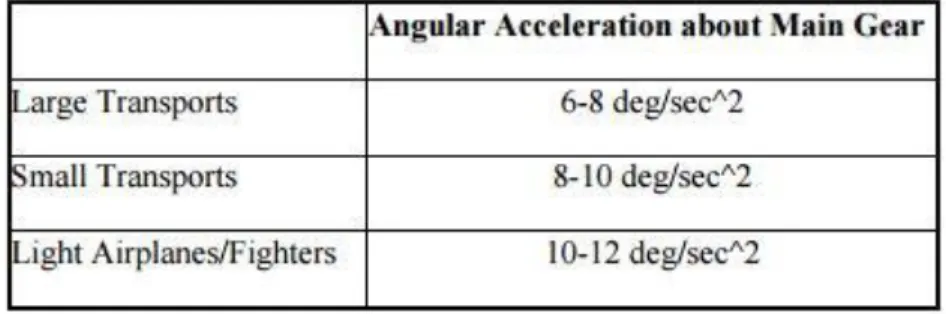
With all these statements, the design can start and as first step, is needed to select the
suitable pitch angular acceleration based on similar aircrafts:
Looking at the table above, a value of 11 deg/sec2 is tentatively selected.
The next step is to calculate the wing-fuselage lift and plane drag. These parameters
are calculated in the Design of the wing for UAV-HALE, but they are calculated separately in
this text and comparing the results to certain both are correct.
What follow is to calculate the linear acceleration during the take-off rotation using
the following equations; first one is the ground friction and the second the line acceleration: Table 2.2.-Angular Acceleration about main gear for different types of aircrafts.
Where µ is the ground friction and for roadway is selected a value of 0.04. The linear
acceleration result to be 3.4 m/s.
The following step is to calculate the contributing pitching moments in take-off rotation
control. This moments are: aircraft weight moment (MW), aircraft drag moment (MD), engine
thrust moment (MT), wing-fuselage lift moment (MLwf), wing-fuselage aerodynamic pitching
moment (MACwf), horizontal tail lift moment (MLh), and linear acceleration moment (Ma). The
equations for those moments are:
Some of these moments helps the plane to climb and other ones make the plane to
fall so, with the elevator we should fight against those moments. This is represented by:
Where the Iyy inertia is needed to be estimated. This estimation is as follows: Equation 2.22 Equation 2.23
Equation 2.24
Equation 2.21 Equation 2.19
Equation 2.20
Equation 2.25
Equation 2.28 Equation 2.27
Is just needed the Iyy estimation where L is the aircraft length, W the aircraft weight
and g the gravity acceleration. Ry is an estimation parameter which is selected with the
following table:
Where the value of 0.397 is selected due to our aircraft is a single high wing aircraft. Is
noticed to know that the result of this formula is on slug·ft2 where 1 slug·ft2 = 0.13826 kg·m·s2. So, the desired tail lift coefficient should be big enough to satisfy the needed pitch
moment:
The result for this aircraft is -0.32 which means that a down force is needed.
The maximum up deflection is for the take-off operation meanwhile the maximum
down deflection is for the longitudinal stability trim.
The elevator design for the take-off rotation is crucial and is needed to determinate
the tail chord to elevator chord ratio with is calculated based on the parameter τe which is
0.28; so as shows the following graphic:
Table 2.3.- Estimation parameters for Inertia estimation
Equation 2.29
This figure shows that for a value of 0.28 the result for the TC-EC is 0.1.
The following parameters are acquired as the longitudinal trim on cruise flight denote.
The pitching moments for the cruise flight are calculated as the calculations for the pitching
moments for the take-off operations due to this aircraft’s gravity center do not change during
the flight.
Due to an optimal design, the perfect situation is where no deflection is needed at
cruise flight. Due to this plane is designed for this proposal, as the following graph shows, it
has been achieved:
However, in any case, a calculation for the most adverse case is done through the
calculation of some longitudinal stability derivates and the equation 2.30.
The result for this operation is 17.65º needed which means that is not needed a full
wing deflector or to change the tail arm.
It becomes necessary to say that if the knowledge about the process to get that value
and the aircraft longitudinal stability derivates is required, is encouraged that follow the steps
and the equations on the elevator m file program for MATLAB, due to this process is long and
pointless for this section.
Finally, the last steps for the elevator calculation is the geometrical parameters defined
by:
𝐶𝑒 𝐶ℎ = 0.1
Which results on Ce = 0.07m and Se = 0.56m2, what means that the 10% of the aircraft is elevator. It seems like a small elevator but it is because the horizontal tail is not that big.
The last thing to show is the horizontal tail lift distribution which shows that it has a
close elliptical lift distribution which are the most wanted or the desired lift distributions due
to the root handle more moment and force than the tip.
What happen for this aircraft at the root is the effect of the vertical tail effect in the
middle.
Equation 2.31
Equation 2.32
2.3.2.
Rudder design
The last device to design is the rudder. This control surface is the responsible for the
aircraft directional control. It is located on the railing edge of the vertical tail. When the rudder
is deflected, a lift force is created what origins a yawing moment about the gravity center of
the aircraft. The two fundamental roles of rudder are directional control and directional trim
but, for and this aircraft that do not have alerions, the directional control is critical due to it
cannot do a baking or a combination turn. The positive point is without this kind of
combination turn the aircraft is less likely to sideslip. But the negative is that the directional
control is poorer and lies all of it on this surface. This means that the required rotation would
be very more slowly. Is supposed that the baking trim is fixed. As the elevator, the rudder
control power must be sufficient to guarantee both requirements.
Like the elevator, the span of the rudder can be as long as the tail or less than it but
this time the full moving vertical tail is not allowed by the time that this tail is a T-tail and is
needed to own the required structure to hold the horizontal tail. The main parameters for the
rudder are rudder area (SR), rudder chord (CR), rudder span (bR), maximum rudder deflection
(±δRmax), location of in board edge of the rudder (bRi). Figure 2.7.- Different combined turn.
In a symmetrical aircraft with a zero-sideslip angle, and without aileron, the yawing
moment is determined by multiplying the vertical tail lift by the vertical tail arm:
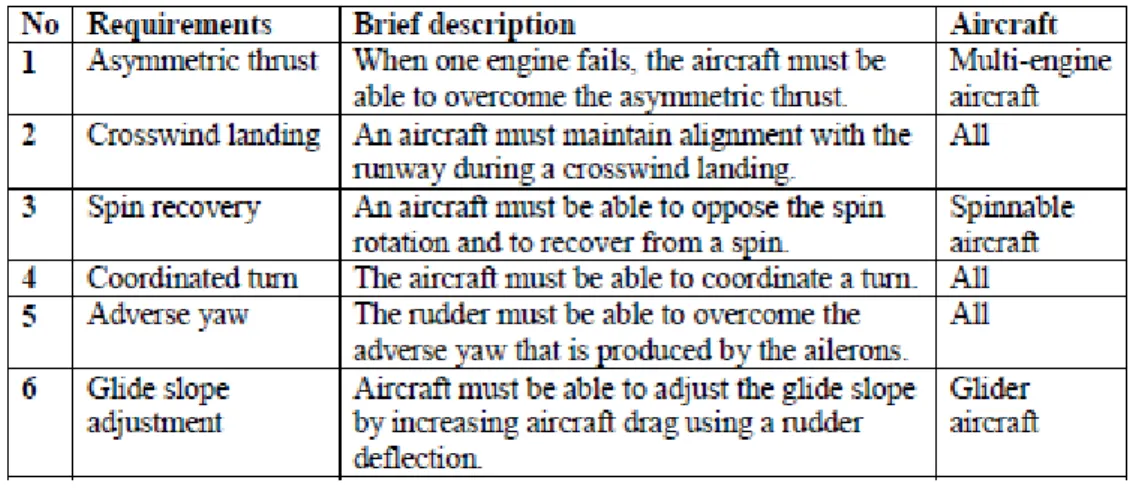
In this section, the rudder design depends on what is the main requirement. These
requirements are asymmetric thrust, crosswind landing, spin recovery, coordinated turn,
adverse yaw and glide slope.
The rudder plays different roles depending in which is the main requirement. For the
aircraft in this text, the 4th requirement is not contemplated. The main requirements Asymmetric thrust, crosswind landing and glide slope adjustment and if the rudder is strong
enough for these requirements would secure to fix other parameters.
Due to this decision, the first thing to determinate is the aircraft approach speed and
the aircraft total speed at landing. For this design, the air speed is selected to be 40 knots or
20 m/s, that is a typical value for a safety landing, and the total aircraft speed at landing would
be 21.03 m/s.
The following step would be to calculate the aircraft moments around the gravity
center approaching the aircraft lateral area and it aerodynamic center and after that balancing
that moment with the vertical tail.
The side force the vertical tail must generate is 2059.19 N that is not a big force for the
huge vertical tail that this UAV has.
As happened with the elevator, the following steps it to calculate the different aircraft
lateral stability derivates which is a long process and pointless to relate it here; due to that is
encourage for those readers that want to know such process to look at the Rudder program. Equation 2.34
Finally, with all those calculations done is possible to enter in the following system of
2 equations with 2 unknowns:
Where δR is the rudder deflection.
Solving these equations is obtained a maximum deflection needed of 6.15º, which is
totally allowable for this vertical tail structure.
Due to check the safety for the other requirements the following step is to check if
the deflection obtained before is enough for meet those other requirements.
The deflection is enough for the asymmetric thrust and for the glide slope adjustment
so any other deflection calculation is required
As in the other sections, the final part is to calculate the rudder geometrical
parameters.
𝐶𝑅
𝐶𝑣 = 0.4
Which parameters result to be a chord of 0.77m long and a surface of 1.96m2. This means that the rudder is the 39.18% of the vertical tail. Which such surface is needed a very
small deflection angle which means that is possible to optimize the rudder surface for future
work; any way this small deflection is good due to generate less drag, less power at the motor
is needed and there is no flow separation that can cause the tail to stall.
Equation 2.35
Equation 2.36
Equation 2.38
Equation 2.37
3.
Operations, results and analysis
In this section are exposed the different calculus, the 3D design which result and the
structure analysis.
3.1.
Calculations (MATLAB programing)
Here is showed the various programs developing for the calculation of the parameters
and the geometrical constrains.
3.1.1.
Programs
Horizontal_Airfoiil.m
% Horizontal Tail Airfoil Selection
function [] = Horizontal_Airfoil()
%Calculates de parameters for the horizontal tail airfoil selection
%Global parameters
global ARw
global Sh
global Clh
global Lopt
global h
global ho
global Sw
global Cmw
global p
global Cw
global vc
global vs
global bw
global Vv
%Variables
Vh = 0.6; %Vol. coefficient for the horizontal stabilizer.
Vv = 0.03; %Vol. coefficient for the vertical stabilizer.
p = 0.10439; %Aprox. air density at cruise altitude.
nh = 1; %Tail efficiency of a T-tail.
vs = 4.04; %Stall speed calculated at Wing design (m/s).
vc = 16.7; %Cruise velocity parameter (m/s).
%Needed variables from the wings to do the calculates
Cw = input('Input the average chord of the wing: '); Sw = input('Input the surface of the wing (m^2): ');
Df = input('Input the maximum diameter of the fuselage (m): '); Cmw = input('Input the wing pitch coefficient: ');
ARw = input('Input the wing Aspect Ratio: '); SAw = input('Input the wing Sweep Angle (º): '); TAw = input('Input the wing Twist Angle (º): ');
Wavg = input('Input the average aircraft weight during the flight (kg): ');
Clw = input('Input the cruise Lift Coefficient of the wings (at the most unfavorable Re at cruising flight): ');
Xcg = input('Input the location of the c.g. from the beginning of the wing (m): ');
bw = input('input the wing span(m): ');
%Calculation of parameters
Lopt = sqrt((4*Vh*Sw*Cw)/(pi*Df)); %Optimum tail moment arm to minimize the
aircraft drag and weight.
%Lopt = 5.5; %Changing the Lopt we change the rest of the parameters to
improve the different parameters (3rd iteration).
Sh = ((Vh*Cw*Sw)/Lopt); %Calculate horizontal tail planform area.
Cmwf = (((Cmw*ARw*cos(SAw)^2)/(ARw+2*cos(SAw)))+0.01*TAw);%Calculate
wing-fuselage aerodynamic pitching moment coefficient.
h = (Xcg/Cw); %non-dimensional aircraft center of gravity position.
Clh = ((Cmwf+Clw*(ho-h))/(nh*Vh)); %Calculate horizontal tail desired lift
coefficient at cruise.
Clhm = ((2*Wavg)/(1.2*vs^2*Sh)); %Calculate the aircraft maximum tail lift
coefficient.
%Print the parameters
disp ('3.- Vh = 0.6; Vv = 0.03 from tables') fprintf(1,'4.- Lopt = %10.2f m \n',Lopt); fprintf(1,'5.- Sh = %10.2f m^2 \n',Sh); fprintf(1,'6.- Cmwf = %10.2f \n',Cmwf); fprintf(1,'7.- Clw = %10.2f \n',Clw); fprintf(1,'8.- Clh = %10.2f \n',Clh); fprintf(1,'9.- Clhm = %10.2f \n',Clhm);
%Show the picture to Select the NACA Airfoil
Airfoil = imread('NacaAirfoilSelection.jpg');
figure('Name','NACA Airfoils','NumberTitle','off'); hold on
Horizontal_Tail.m
% Horizontal Tail
function [] = Horizontal_Tail()
%Calculates de parameters for the horizontal tail airfoil selection
%Variables
global ARw
global Sh
global Clh
global ARh
global h
global ho
global Sw
global Lopt
global Clah
global i_h
global Cla
global TRh
global a_h
global bh
global MACh
nh = 1; %Tail efficiency of a T-tail.
%Warning box
if ARw == true
h = warndlg('Run Horizontal_Airfoil.m first'); end
%Needed variables from the wings to do the calculates
TRh = input('Input the Taper Ratio of the wing: '); %In early design
the Tail TR is the same or aprox. the same as Wing TR.
Cla = input('Input the Lift Curve Slope from the selected airfoil (1/rad): ');
a_w = input('Input the cruise wing attack angle(deg): ');
Clah = (Cla/(1+(Cla/(pi*ARh)))); %Lift Curve Slope for the horizontal tail
(2D).
a_h = Clh/Clah; %Angle of attack in cruise.
fun = @root2dh; %System of 2 nonlinear eq.
x0 = [5,5];
x = fsolve(fun,x0); bh = x(1); %Tail Span
MACh = x(2); %Tail Main Aerodynamic Chord
Ch_root = ((MACh*3)/(2*((1+TRh+TRh^2)/(1+TRh)))); %Chord when the Tail is
close to the fuselage.
Ch_tip = (TRh*Ch_root); %Chord at the end of the tail.
%With the angle of attack calculated is needed to know the real
tail lift coefficient
%Applying the lifting line theory:
Error = 10; cont = 1;
N = 9; % (number of segments-1)
alpha_0 = 0.000001; % zero-lift angle of attack (deg) (symmetric)
alpha_twist = 0.0000001; %twist angle
while Error > 0.001 %Bucle to obtain the desire angle of attack
if cont == 0
if CL_tail < Clh a_h = a_h-0.01; elseif CL_tail > Clh a_h = a_h+0.01; end
end
bh = sqrt(ARh*Sh); % tail span
MAC = Sh/bh; % Mean Aerodynamic Chord
Croot = (1.5*(1+TRh)*MAC)/(1+TRh+TRh^2); % root chord
theta = pi/(2*N):pi/(2*N):pi/2;
alpha = (a_h+alpha_twist):(-alpha_twist/(N-1)):(a_h); % segment's
angle of attack
c = Croot * (1 - (1-TRh)*cos(theta)); % Mean Aerodynamics chord at
each segment
mu = (c * Clah) / (4 * bh);
LHS = (mu .* (alpha-alpha_0)) /57.3; % Left Hand Side
% Solving N equations to find coefficients A(i):
for i=1:N
for j=1:N
B(i,j) = (sin((2*j-1)*theta(i))*(1+(mu(i)*(2*j-1))/sin(theta(i))));
end
end
A = (B\transpose(LHS)); for i = 1:N
sum1(i) = 0; sum2(i) = 0; for j = 1:N
sum1(i) = (sum1(i)+(2*j-1)*A(j)*sin((2*j-1)*theta(i))); sum2(i) = (sum2(i)+A(j)*sin((2*j-1)*theta(i)));
end
end
CL_tail = (pi*ARh*A(1));
Error = (CL_tail/Cla)*100; cont = 0;
end
%Calculation of parameters
epsilon = (1+0.3*(a_w/57.3)); %Downwash angle.
i_h = a_h + epsilon - 0; % (0 = fuselage angle of attack at cruise)
Horizontal tail incidence angle.
%Calculate the stability
Claw = ((0.3*pi*ARw)/2); %Approximate wing lift curve.
Cma = ((Claw*(h-ho))-(Clah*nh*(Sh/Sw)*((Lopt/MACh)-h)*(1-0.3))); %Must be
negative to static horizontal stability
%Print the parameters
disp ('10.- Tail sweep = 0º; Dihedral angle = 0º')
fprintf(1,'11.- ARh = %10.2f; TRh = %10.2f \n',ARh, TRh); fprintf(1,'12.- Clah = %10.2f 1/rad \n',Clah); %Lift curve slope
fprintf(1,'13.- a_h = %10.2f º \n',a_h); %attack angle
fprintf(1,'14.- epsilon = %10.2f º \n',epsilon); %Downwash angle
fprintf(1,'15.- i_h = %10.2f º \n',i_h); %incidence angle
fprintf(1,'16.- bh = %10.2f m; MACh = %10.2f m; Ch_root = %10.2f m; Ch_tip = %10.2f m\n',bh,MACh,Ch_root,Ch_tip);
fprintf(1,'17.- Cma = %10.2f 1/rad; this must be negative to static horizontal stability \n',Cma);
end
Where root2dh.m is the following function:
function F = root2dh(x)
global Sh
global ARh
F = [((x(1)*x(2)-Sh)); (((x(1))/x(2))-ARh)];
Vertical_Tail.m
% Vertical Tail
function [] = Vertical_Tail()
%Calculate de parameters for the vertical tail
%Global parameters
global Lopt
global Sw
global ARv
global Sv
global bv
global MACv
%Variables
Vh = 0.6; %Vol. coefficient for the horizontal stabilizer.
Vv = 0.03; %Vol. coefficient for the vertical stabilizer.
p = 0.10439; %Aprox. air density at cruise altitude.
ho = 0.25; %non-dimensional wing-fuselage aerodynamic center.
nh = 1; %Tail efficiency of a T-tail.
vs = 4.24; %Stall speed calculated at Wing design (m/s).
vc = 14; %Cruise velocity parameter (m/s).
ARv = 1.33; %Vertical aspect ratio.
TRv = 0.9; %Vertical taper ratio.
incidence_angle = 0; %Vertical incidence.
Sweep_angle = 10; %Vertical sweep.
Diedral_angle = 0; %Vertical Dihedral. (not allowed with one vertical
tail).
%Warning box
if Sw == true
h = warndlg('Run Horizontal_Airfoil.m first'); end
%Needed variables from the wings to do the calculates
b = input('Input the wing span (m): ');
%Calculation of parameters
bv = (sqrt(ARv*Sv)); %Vertical span.
MACv = (bv/ARv); %Vertical main chord.
Cv_root = ((MACv*3*(1+TRv))/(2*(1+TRv+TRv^2))); Cv_tip = (TRv*Cv_root);
%Print the parameters
disp ('1.- T-tail') disp ('2.- aft')
disp ('3.- Vv = 0.03 from tables')
fprintf(1,'4.- Lopt = %10.2f m \n',Lopt);%For the design is supposed to be
the same as the horizontal one.
fprintf(1,'5.- Sv = %10.2f m^2 \n',Sv);
disp ('6.- Airfoil section selected for the Vertical Tail is
NACA-64-008')%Due to symmetric, no compress effects and good lift curve.
disp ('7.- The selected ARv = 1.33 based on other similar aircrafts') disp ('8.- The selected TRv = 0.9 based on other similar aircrafts') disp ('9.- The selected Incidence angle = 0º based on other similar aircrafts')
disp ('10.- The selected Sweep angle = 10º based on other similar aircrafts')
disp ('11.- The selected Dihedral angle = 0º based on other similar aircrafts')
fprintf(1,'12.- bv = %10.2f m, MACv = %10.2f m, Cv_root = %10.2f m, Cv_tip = %10.2f m \n',bv,MACv,Cv_root,Cv_tip);
Elevator_Design.m
% Elevator Design
function [] = Elevator_Design()
%Provides the parameters to design de Elevator
%Global parameters
global ARw
global ARh
global Sh
global h
global ho
global Sw
global Cmw
global Cw
global vs
global Clah
global i_h
global Cla
global p
global vc
global bh
global Xfcg
global Tmax
global MACh
global TRh
%Variables
bebh = 1;
VR = (12*2*pi)/360; %Take off pitch angular acceleration for this kind of
aircrafts.(rad/s^2)
po = 1.21; %Average air density.
Tmax = 168.80; %Motor Thrust.
Zmg = 0; %Landing gear high.
delta_up = (-20*2*pi)/360; %Maximum elevator deflection
alpha_hs = 10; %Horizontal airfoil stall angle (deg)
%Needed variables from the wings to do the calculates
Clto = input('input the lift wing-fuselage coefficient at take-off: ');
Xmg = input('input the distance from the nose to the main landing gear(m): ');
Xfcg = input('input the distance from the nose to the most forward gravity center(m): ');
Zd = input('input the altitude of the wings from the ground(m): '); Zt = input('input the altitude of the propeller from the ground(m): ');
Xacwf = input('input the distance of the aerodynamic center of the wing from the nose(m): ');
Zcg = input('input the altitude of gravity center from the ground(m): ');
Xach = input('input the distance from the nose to the aerodynamic center of the horizontal tail(m): ');
a_wto = input('input the take off attack angle(deg): '); Iyy = input('input the Inertia about y axis(kg*m^2): ');
%Calculation of parameters
Dto = 0.5*po*vs^2*Sw*Cdto; %Drag at take off
Lto = 0.5*po*vs^2*Sw*Clto; %Lift at take off
Cwf = 0.5*po*vs^2*Cmw*Sw*Cw; %Pitch wing-fuselage
FR = 0.04*(50*9.81 - Lto);
a = ((Tmax-Dto-FR)/50); %Acceleration at take off
%Calculation of pitching moments
Mw = -50*9.81*(Xmg-Xfcg); Md = Dto*(Zd-Zmg);
Mt = -Tmax*(Zt-Zmg); Mlwf = Lto*(Xmg-Xacwf); Ma = 50*a*(Zcg-Zmg);
Lhto = ((Mlwf+Cwf+Ma+Mw+Md+Mt-Iyy*VR)/(Xach-Xmg)) ; %Desired horizontal
tail lift at take off
Clhto = ((2*Lhto)/(po*vs^2*Sh)); %Desired tail lift coefficient
%Calculation of the ideal angle of attack at take-off
epsilon_o = ((2*Clhto)/(pi*ARw)); %Downwash effect.
D_epsilon = ((2*Cla)/(pi*ARw)); %Downwash effect.
epsilon = epsilon_o+(D_epsilon*(a_wto/57.3)); %Downwash angle.
Tao_e = abs((((a_hto/57.3)+(Clhto/Clah))/delta_up)); %angle of attack
effectiveness of the elevator
%Print the parameters
disp ('1.- Take-off rotation. \n Longitudinal trim requirements. \n Low cost. \n Manufactural.')
disp ('2.- VR = 12 deg/seg^2 based on similar aircrafts.') %take-off pitch
angular acceleration
disp ('3.- be/bh = 1 based on similar aircrafts.')
%elevator-span-to-tail-span ratio
disp ('4.- delta_up = -20 º.') %elevator maximum deflection
fprintf(1,'5.- Drag-at-take-off = %10.2f N, Lift-at-take-off = %10.2f N,
Pitch = %10.2f N*m \n',Dto,Lto,Cwf); %Forces
fprintf(1,'6.- a = %10.2f m/s^2 \n', a); fprintf(1,'7.- Lhto = %10.2f N \n', Lhto); fprintf(1,'8.- Clhto = %10.2f \n', Clhto);
fprintf(1,'9.- a_hto = %10.2f rad, Tao_e = %10.2f \n',a_hto,Tao_e);
%Show the picture to Select the NACA Airfoil
Airfoil = imread('Effectiveness to Cs-Ls area ratio.jpg');
figure('Name', 'Selection of the Ce/Ch ratio','NumberTitle','off'); hold on
image(Airfoil);
%%%%%%%%%%%%%%%%%%%%%%%%%%Second part of the program
CeCh = input('Select the correct number of the Elevator-chord-to-tail-chord ratio based on the picture and on the Tao_e valor: ');
if CeCh > 0.5
disp ('suggested to select an all moving tail'); end
if Tao_e > 1
end
%calculation of parameters
Delta_alpha_oe = -1.15*CeCh*(delta_up*(360/2*pi)); %change in the tail lift
coefficient when the elevator is deflected
%Lifting line theory optimization
N = 9; % (number of segments - 1)
alpha_twist = 0.000001; % Twist angle (deg)
alpha_0 = 0.000001 + Delta_alpha_oe; % zero-lift angle of attack
(deg)
a_0 = Delta_alpha_oe; % flap up zero-lift angle of attack (deg)
bh = sqrt(ARh*Sh); % wing span (m)
a_0_fd = 0.00001; % flap down zero-lift angle of attack (deg)
MAC = Sh/bh; % Mean Aerodynamic Chord
Croot = (1.5*(1+TRh)*MAC)/(1+TRh+TRh^2); % root chord
theta = pi/(2*N):pi/(2*N):pi/2;
alpha=i_h+alpha_twist:-alpha_twist/(N-1):i_h; % segment's angle of
attack
for i=1:N
if (i/N)>(1-CeCh)
alpha_0(i)=a_0_fd; %flap down zero lift AOA
else
alpha_0(i)=a_0; %flap up zero lift AOA
end
end
z = (bh/2)*cos(theta);
c = Croot * (1 - (1-TRh)*cos(theta)); % MAC at each segment
mu = c * Clah / (4 * bh);
LHS = mu .* (alpha-alpha_0)/57.3; % Left Hand Side
% Solving N equations to find coefficients A(i)
for i=1:N
for j=1:N
B(i,j) = sin((2*j-1) * theta(i)) * (1 + (mu(i) * (2*j-1)) / sin(theta(i)));
end
A=B\transpose(LHS);
for i = 1:N sum1(i) = 0; sum2(i) = 0; for j = 1 : N
sum1(i) = sum1(i) + (2*j-1) * A(j)*sin((2*j-1)*theta(i)); sum2(i) = sum2(i) + A(j)*sin((2*j-1)*theta(i));
end
end
CL = 4*bh*sum2 ./ c;
CL1=[0 CL(1) CL(2) CL(3) CL(4) CL(5) CL(6) CL(7) CL(8) CL(9)]; y_s=[bh/2 z(1) z(2) z(3) z(4) z(5) z(6) z(7) z(8) z(9)];
plot(y_s,CL1,'-o') grid
title('Lift distribution')
xlabel('Semi-span location (m)') ylabel ('Lift coefficient')
CL_TO = pi * ARh * A(1);
%%%%%%%%%%%%%%%%%%%%%%%%%%%%%%%%%%%%%%%%%%
xlh = input('input the distance from the tail to the most aft cg(m): '); Clo = input('input the zero lift angle of attack for the wing(º): ');
Vh = ((xlh+Sh)/(Sw*Cw));
Cm_d = -Clah*1*Vh*bebh*Tao_e; %-0.2/-4
Cl_d = Clah*1*(Sh/Sw)*bebh*Tao_e; Clh_d = Clah+Tao_e;
%Calculation of the most down deflection
Cm_a = Cla*(h-ho)-Clah*1*(Sh/Sw)*(xlh/Cw)*(1-D_epsilon); q = 0.5*vc^2*p;
C_Ll = ((2*50*9.81)/(p*vc^2*Sw));
delta_down_deg = delta_down*(180/pi);
%Display more results
fprintf(1,'10.- Delta_alpha_oe = %10.2f º\n', Delta_alpha_oe);
fprintf(1,'11.- CL_OT = %10.2f calculated and Clhto = %10.2f desired; If
the first is bigger than the desired one, in absolute value, the elevator is acceptable.\n', CL_TO,Clhto);
fprintf(1,'12.- delta_down = %10.2f º\n', delta_down_deg);
%%%%%% Ploting the variations of the deflection
Cmo = 0; CLa_wf = Cla; g = 9.81; %m/s^2
m = 50; % kg
etha_h = 1;
xlh = Xach-Xmg; % m from main landing gear
CLdE=-Clah*etha_h*Sh*Tao_e/Sw;
% Most forward cg
xcg = input('input the most forward cg position from main landing gear(m): ');
h_to_ho = -0.3/Cw; % m
l_h2 = xlh+xcg; % m
VH2 = (l_h2*Sh)/(Sw*Cw);
CmdE2 = -Clah*etha_h*VH2*Tao_e;
Cma2 = CLa_wf*h_to_ho-Clah*etha_h*Sh*(l_h2/Cw)*(1-D_epsilon)/Sw; i =1;
for U1=vs:vc;
plot(V,dE2,'*') grid
xlabel ('Speed (m/s)') ylabel ('\delta_E (deg)') legend('Most forward cg')
disp('Check if the delta_down and delta_up is between the values in the graph')
%%%%%%%%%%%%%%%%%%%%%%%%%%%%%%%%%%%%%%%%%%%%%%%%%%%%%%%%%
alpha_s = input('input the wing stall angle(deg): ');
alpha_to = alpha_s - 2; %For security we set the maximum angle at take-off
under 2 deg of the wing stall angle
alpha_hto = alpha_to*(1-D_epsilon)+i_h-epsilon_o;
if alpha_hto < (alpha_hs-2)
disp('The horizontal tail do not stall during take-off rotation') else
disp('The horizontal tail stall during take-off rotation; check parameters[reduce elevator deflection and/or elevator chord]') end
%Final parameters
Ce = CeCh*MACh; %Elevator length.
Se = bh*Ce; %Elevator surface.
fprintf(1,'13.- Ch = %10.2f m, Ce = %10.2f m, Se = %10.2f m^2\n', MACh, Ce, Se);
![Figure 1-5.- Position of the wing [29].](https://thumb-us.123doks.com/thumbv2/123dok_es/6132411.179688/14.893.93.787.179.544/figure-position-of-the-wing.webp)
![Figure 2.2.- AFT configurations [29].](https://thumb-us.123doks.com/thumbv2/123dok_es/6132411.179688/23.893.203.689.617.927/figure-aft-configurations.webp)
![Figure 2.4.- N.A.C.A. airfoils [29].](https://thumb-us.123doks.com/thumbv2/123dok_es/6132411.179688/27.893.218.687.559.1159/figure-n-a-c-a-airfoils.webp)