Dual Polarized Reflectarray Antenna to Generate
Independent Beams in Ku and Ka Bands
Eduardo Martinez-de-Rioja , José A. Encinar , Rafael Florencio , Rafael R. Boix
Abstract—This contribution describes the design of a printed reflectarray antenna for operating at Ku and Ka frequency bands. The reflectarray has been designed to produce a focused beam at 11.95 and 20 GHz for both Horizontal and Vertical polarizations. The antenna is illuminated by a corrugated horn, modelled as a cos-q function with different q-factor values at 11.95 and 20 GHz. The periodic element is made of two stacked sets of dipoles, each of one comprising two orthogonal subsets of coplanar parallel dipoles, whose lengths are adjusted to focus the beam at each polarization and frequency band. The dimensions of all dipoles are calculated for a circular reflectarray of 33x33 elements (33-cm sided), using a MoM-SD based analysis routine and local periodicity approach. The simulated radiation patterns of the antenna show a gain of 30.7 dBi at 11.95 GHz and 34.2 dBi at 20 GHz, with side-lobe levels close to -21 dB.
Index Terms—reflectarray, dual polarization, dual band, parallel dipoles, satellite communications.
I. INTRODUCTION
Reflectarray antennas consist of a planar arrangement of printed elements on a dielectric substrate over a ground plane. When the antenna is illuminated by a feed, the phase of the reflected field on each element can be adjusted to produce a focused or a shaped beam. Commonly, this task is accomplished by varying the dimensions of the printed elements [1].
The interest on reflectarray antennas has increased in the last years, due to their low fabrication cost and ease of integration, as well as the high values of gain, radiation efficiency and beam scanning range that can be reached [2]. This type of antennas has been used for generating co llimated and contoured beams in different applications: satellites, radar, point-to-multipoint communications, etc. Its main drawback remains on their narrow bandwidth, which is usually around 10%. Several techniques have been proposed to mitigate this problem, such as stacked multi-layer structures [3], usage of parallel dipoles [4] and frequency optimization routines [5].
In this paper, the authors present the design of a dual linearly polarized reflectarray antenna to operate separately in Ku and Ka frequency bands, producing a focused beam at 11.95 and 20 GHz, with low levels for cross-polar radiation. This antenna will allow for a key reduction in volume and cost in communication satellites that operate at these frequency bands.
II. PERIODIC ELEMENT
Two reflectarray cells based on a stacked two-layer structure and orthogonal sets of parallel dipoles are studied, so as to provide enough degrees of freedom to design a high performance reflectarray antenna. The reason for choosing this structure is to reach a simple periodic element with a low number of layers (which means less cost of manufacturing), offering dual band and dual polarization operation.
Phase shining can be implemented by adjusting the lengths of all dipoles in the way that follows. Horizontal dipoles will control the phase response for H-polarization, while vertical dipoles will complete the same task for V-polarization. The length of dipoles in lower layer will be larger than the length of those on the top layer, so that upper dipoles will not disturb the reflectarray phase response at 11.95 GHz, and lower dipoles will behave as a ground plane at 20 GHz for higher layer elements. Two configurations with different number of dipoles are proposed.
A. Two- layer reflectarray cell with six dipoles for each polarization
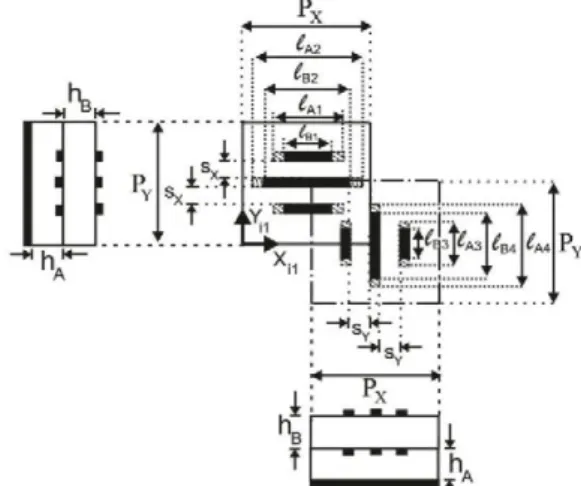
The basic periodic element, shown in Fig. 1, consists of two orthogonal sets of dipoles. Each set comprises three coplanar parallel dipoles printed on a dielectric layer, and three additional parallel dipoles, which are stacked with the central one and are printed on the top of a second dielectric sheet. The lateral dipoles are symmetric with respect to the central one, in order to keep low levels of cross-polarization.
The period Px = Py = 10 mm is chosen as 0.66X at 20 GHz
for a maximum angle of 30° (incidence on the reflectarray edge elements or beam pointing direction), according to the expression provided in [2] (p. 84) to avoid the appearance of grating lobes. Commercially available materials have been used to implement both dielectric layers, their main parameters are: relative permittivity erA= 2.55, erB= 2.17; loss
tangent tan(5A) = 0.0022, to«(5B) = 0.002; and thickness hA=
2.363 mm, hB= 1.5 mm.
Regarding the dipoles, the following parameters have been chosen to provide a smooth variation in phase response and cover a wide range of phase in both frequency bands: dipole width w = 0.5 mm; separation between laterally coupled dipoles SXA =SYA =1.5 mm, SXB =SYB =1.5 mm; and relative sizes of lateral dipoles /A1 = 0.63 -l^, l^ = 0.63/A4, /B1 =
B. Two- layer reflectarray cell with eight dipoles for each polarization
An alternative reflectarray cells has been proposed. It comprises two sets of five coplanar parallel dipoles printed on a dielectric layer, and three additional parallel dipoles, which are stacked with the central one and are printed on the top of a second dielectric sheet. The reason for introducing this modification on the cell is to obtain a greater stability in phase response at 20 GHz and provide an additional length variable for the implementation of design process in each polarization.
The following parameters have been chosen to provide a smooth variation in phase response and cover a wide phase range in both frequency bands: dipole width w =0.5 mm; separation between laterally coupled dipoles SXA =SYA =0.5
mm, SXB =SYB =1.5 mm; and relative sizes of lateral dipoles
lA1= 0.59·lA3, lA2= 0.75·lA3, lA4= 0.59·lA6, lA5= 0.75·lA6 (where
lA3 and lA6 correspond now to the central dipoles’ lengths), lB1=
0.8·lB2, lB3 = 0.8·lB4.
Fig. 1. Upper and lateral views of the basic reflectarray element, which includes one cell for H-polarization and one cell for V-polarization.
C. Amplitude and phase response for the two proposed reflectarray cells
The simulated phase and amplitude curves of the co-polar reflection coefficient are shown in Fig. 2 for both reflectarray cells, for H-polarization and 6 = 20º, cp = 0° angle of incidence (related to the central part of the reflectarray that is described in next section). Note that a similar response will be obtained for V-polarization. The results are presented as a function of the central dipole lengths in X-direction: lower central dipole in Fig. 2.a, and upper central dipole in Fig. 2.b. The phase and amplitude responses are similar for both proposed reflectarray cells. Smooth variations in phase are achieved, especially in Ku band, and the encompassed phase range is wide enough (more than 360º) to perform the dual-band design process.
It should be remarked that the curves in Fig. 2 are only used for the periodic element characterization. During the subsequent design process, the real angle of incidence on each reflectarray element will be taken into account to calculate the phase of the reflection coefficient and adjust the lengths of the dipoles. This variation on the angle may slightly modify the trace of the curves.
(a)
(b)
Fig. 2. Phase and amplitude of the copolar reflection coefficient for H -polarization: (a) at 11.95 GHz, (b) at 20 GHz.
I I I . DESIGN PROCESS
for a compromise between the illumination and spillover efficiencies to maximize the gain, the edge illumination level is set to -10.2 dB at 11.95 GHz and -11.8 dB at 20 GHz.
The reflectarray has been designed to produce two focused beams in the directions 6b= 13°, cpb= 0° for H-polarization and
eb= 20°, cpb= 0° for V-polarization at both frequency bands,
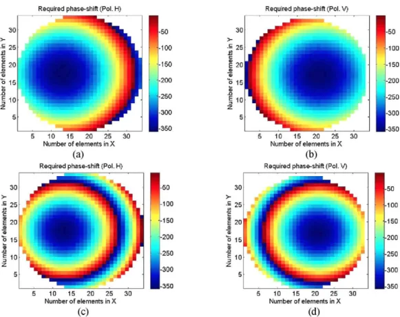
using the two types of cell described in Section II. The required phase-shift on each reflectarray element for a single polarization will be achieved by adjusting the dimensions of the two parallel dipole subsets placed on each layer, according to the phase distributions shown in Fig 4 (see [2], p.34). The length of dipoles in layer A will be larger than the length of dipoles in layer B, so that upper dipoles will not disturb the reflectarray phase response at 11.95 GHz, and lower dipoles will behave as a ground plane at 20 GHz. Due to this operation mode, the lengths needed to match the required phase distributions can be calculated separately for each frequency band, considering only the dipoles in one of the two layers. This factor allows for performing an easier and computationally faster antenna design process.
Longer dipoles will be located in those elements with phase-shift values close to -360°, according to the phase curves showed in the previous section. The majority of these elements are placed in the most illuminated part of the antenna (near to its geometrical center), with incidence angles between 6 =10° and 6 =20°. An appropriate election of phase constants for the simulation will be done in order to minimize the errors in this zone of the reflectarray, which will be decisive in shaping the antenna radiation pattern.
Fig. 3. Reflectarray antenna, with feed-horn position and reference coordinate systems.
To perform the dipole lengths adjustment, it is employed an iterative zero-finding procedure which calls a software analysis routine, based on the Method of Moments in the Spectral Domain (MoM-SD) and the local periodicity approach. This routine takes into account the real angle of incidence 6i on each reflectarray element to calculate the
amplitude and phase of the reflexion coefficient, considering the element in a periodic environment. This home-made software provides a fast calculation tool, whose accuracy has been checked in previous works by comparing with the results obtained with commercial software CST and the measurements of manufactured reflectarray prototypes [4].
Number of elements i;
(c)
Number of elements i;
(d)
First, the dipoles on the bottom layer are adjusted to provide the required phase-shift at 11.95 GHz, and then those on the top layer are adjusted to produce the required phase at 20 GHz. Once the design is completed, independently for each frequency, a further optimization is run, in which the dimensions of all dipoles are optimized element-by-element to simultaneously match the phases at the central and extreme frequencies in Ku (10.95-12.95 GHz) and Ka (19.5-20.5 GHz) bands, following a procedure very similar to that shown in [5]. The optimization can be separately run for horizontal and vertical dipoles, since the phase response is practically uncoupled in the two polarizations H and V .
I V . RESULTS AND DISCUSSION
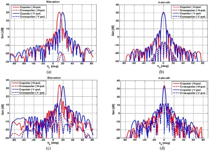
The radiation patterns in gain are shown in Fig. 5 for the (6+6) element antenna and in Fig. 6 for the (8+8) element antenna. The results are presented for the central frequency of each band in the elevation and azimuth orthogonal planes (note that azimuth planes form 13º and 20º with Z-axis for H and V polarization, respectively). They include both co-polar and cross-polar components of the radiated field for each polarization. The radiation patterns have been obtained from the tangential reflected field at each reflectarray element, using the home-made MoM-SD software described in Section III. The electric field on the aperture of the feed-horn has been
used to compute the incident field on the reflective surface. It can be observed that a 30.7 dBi gain is reached at 11.95 GHz, and 34.15 dBi gain is reached at 20 GHz, with low levels for cross-polar components. The beam is focused in the direction 6b = 13°, cpb = 0° for H-polarization, and 6b = 20°, cpb =
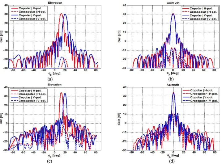
0° for V-polarization, as it was intended. The patterns at 11.95 GHz are very similar in both cases, with side-lobe level close to -21 dB. The employment of the second cell structure, with eight dipoles for each polarization, results in a more accurate beam-shaping at 20 GHz, with an important reduction in side-lobe level (from -20 to -23 dB). Moreover, this configuration contributes to leveling the results for H and V polarizations.
After the multi-frequency optimization, the available bandwidth centred at 11.95 GHz is around 2 GHz (16%) with a gain variation less than 1 dB. Furthermore, 1 GHz bandwidth is reached at 20 GHz (5%) with the same gain variation. These results have been obtained considering the (8+8) element reflectarray, since the design made with the first cell structure showed a worse response against frequency shifts respect to the central frequency of designing.
The conducted simulations take into account most of the losses, such as spillover, illumination and dielectric losses. The antenna radiation efficiency can be estimated at 68% in Ku band and 54% in Ka band, which are typical values for conventional parabolic reflectors.
(c) (d)
(c) (d)
Fig. 6. Simulated radiation patterns for (8+8) element antenna: (a) XZ-plane at 11.95 GHz, (b) superposition of cuts in planes forming 13º (H) and 20º (V) respect to Z axis at 11.95 GHz, (c) XZ-plane at 20 GHz, (d) superposition of cuts in planes forming 13º (H) and 20º (V) respect to Z axis at 20 GHz.
V. CONCLUSIONS
A 33-cm-diameter circular reflectarray antenna has been designed to operate in Ku and Ka frequency bands with dual linear polarization. The proposed cell structure for the reflectarray element consists of two stacked layers, each of them comprising two orthogonal sets of coplanar parallel dipoles. Two variations of this structure have been studied, providing four and five degrees of freedom for each polarization. The lengths of the dipoles have been optimized to meet the required phase-shift distributions at each band and polarization. Simulations show a great behaviour of the antenna in both frequency bands, with gain values greater than 30 dB and side-lobe levels close to -20 dB.
These results show the potential of reflectarray antennas for working at different bands, with independent beam-shaping in each polarization and band. Furthermore, the ease of integration and the reduction in cost, with only two layers, are clearly appreciated. This may be a key factor in communication satellites that operate in Ku and Ka bands, where volume and weight are determining issues. One of the next steps will be the manufacturing and measurement of a reflectarray prototype to corroborate the simulation results.
ACKNOWLEDGMENT
This work was supported by the Spanish Ministry of Economy and Competitiveness under the project TEC2013-43345-P and by the Regional Government of Madrid under project S P A D E R A D A R - C M (P2013/ICE-3000).
REFERENCES
[1] D . M . Pozar, T . Metzler, “Analysis of a Reflectarray Antenna Using Microstrip Patches of Variable Size”, Electronic Letters, Vol. 29, No. 8, pp. 657-658, 15th April 1993.
[2] J. Huang and J. A . Encinar, “Reflectarray Antennas”, IEEE Press/Wiley, Piscataway, New Jersey, 2008.
[3] J. A. Encinar, “Design of Two-Layer Printed Reflectarrays Using Patches of Variable Size”, I E E E Transactions on Antennas and Propagation, Vol. 49, No. 10, pp. 1403-1410, October 2001.
[4] R . Florencio, J . A . Encinar, R . R . Boix, V . Losada, G . Toso, “Reflectarray Antennas for Dual Polarization and Broadband Telecom Satellite Applications,” I E E E Trans. on Antennas and Propagation. Special Issue on Space Antennas, Vol. 63, pp. 1234-1246, April 2015. [5] J. A. Encinar, J. A . Zornoza, “Broadband Design of Three-Layer Printed
Reflectarrays,” I E E E Transactions on Antennas and Propagation, Vol. 51, No. 7, pp. 1662–1664, July 2003.