EVALUACIÓN FINAL
PRUEBA DE HABILIDADES PRÁCTICAS CISCO CCNP
NÉSTOR ALBEIRO RODRÍGUEZ MUÑOZ
UNIVERSIDAD NACIONAL ABIERTA Y A DISTANCIA - UNAD INGENIERÍA ELECTRÓNICA
DIPLOMADO CISCO CCNP IBAGUÉ
PRUEBA DE HABILIDADES PRÁCTICAS CISCO CCNP
NÉSTOR ALBEIRO RODRÍGUEZ MUÑOZ
Diplomado de profundización cisco CCNP prueba de Habilidades prácticas
Director:
Ingeniero Gerardo Granados Acuña
UNIVERSIDAD NACIONAL ABIERTA Y A DISTANCIA - UNAD INGENIERÍA ELECTRÓNICA
DIPLOMADO CISCO CCNP IBAGUÉ
3
NOTA DE ACEPTACIÓN
Presidente del Jurado
Firma del Jurado
Firma del Jurado
4
AGRADECIMIENTOS
5
Tabla de contenido
Agradecimientos ... 4
Glosario ... 10
Resumen ... 11
Introducción ... 12
Desarrollo ... 13
Escenario 1 ... 13
Escenario 2 ... 27
Conclusiones ... 45
6
Lista De Ilustraciones
Ilustración 1. escenario1 ... 13
Ilustración 2 escenario 1 simulación ... 13
Ilustración 3 escenario 2 ... 27
Ilustración 4 escenario 2 simulación ... 27
Ilustración 5 escenario 2 simulación apagado ... 28
7
Lista de tablas
8
Lista de figuras
Figura 1 se configura ipv4 en r1 ... 14
Figura 2 se configura ipv6 en r2 ... 15
Figura 3 se configura ipv6 en r3 ... 16
Figura 4 ajusta reloj r1 ... 16
Figura 5 ajuste reloj r2 ... 17
Figura 6 ajuste reloj r2 ... 17
Figura 7 configuración ospfv3 r2 ... 17
Figura 8 configuración ospfv3 r2 ... 18
Figura 9 configuración f0/0 en area1 r2 ... 18
Figura 10 config f0/0 conexión serial r3 ... 19
Figura 11 config area1 area total stubby r2 ... 20
Figura 12 propagación de ruta ipv4 y ipv6 r3 ... 20
Figura 13 config protocolo eigpr para ipv4-ipv6 r1 ... 21
Figura 14 config protocolo eigpr para ipv4-ipv6 r2 ... 22
Figura 15 config interfaces eigrp r1 ... 22
Figura 16 config redistribución entre ospf y eigrp r2 ... 23
Figura 17 publicidad en ruta r2 ... 24
Figura 18 show ip route r1 ... 24
Figura 19 show ip route r2 ... 25
Figura 20 show ip route r3 ... 25
Figura 21 show ip interface brief r1 ... 25
Figura 22 ping r1 ... 26
Figura 23 show access-lists r2 ... 26
Figura 24 conexión entre dls2 y dls1 ... 30
Figura 25 conexión entre dls1 y dls2 ... 30
Figura 26 port-channels fa0/7 y fa0/8 dls1 ... 31
Figura 27 port-channels fa0/7 y fa0/8 dls2 ... 31
Figura 28 port-channels fa0/7 y fa0/8 als1 ... 32
Figura 29 port-channels fa0/7 y fa0/8 als2 ... 32
Figura 30 port-channels fa0/9 y fa0/10 dls1 ... 33
Figura 31 port-channels fa0/9 y fa0/10 dls2 ... 33
Figura 32 port-channels fa0/9 y fa0/10 als1 ... 34
Figura 33 port-channels fa0/9 y fa0/10 als2 ... 34
Figura 34 vlan 800 vlan nativa dls1 ... 35
Figura 35 vlan 800 vlan nativa dls1 ... 36
Figura 36 config vtpv3 dls1 ... 36
Figura 37 suspender vlan 434 dls1 ... 38
9
Figura 39 spannig-tree vlan dls1 ... 38
Figura 40 spannig-tree vlan root dls2 ... 39
Figura 41 config vlan dls1 ... 40
Figura 42 config vlan dls2 ... 40
Figura 43 config vlan als1 ... 41
Figura 44 show vlan dls1 ... 42
Figura 45 show ip interface brief ... 42
Figura 46 show vlan dls1 ... 43
Figura 47 show spanning-tree dls1 ... 43
10 GLOSARIO
CCNP: Cisco Certified Network Professional) valida la capacidad de planificar, implementar, verificar y solucionar problemas en redes empresariales LAN y WAN, así como trabajar de manera conjunta con especialistas de soluciones de: seguridad, voz, inalámbricas y video (UNA, 2019).
GNS3: es un simulador gráfico de red lanzado en 2008, que te permite diseñar topologías de red complejas y poner en marcha simulaciones sobre ellos,123 permitiendo la combinación de dispositivos tanto reales como virtuales (Wikipedia, 2014).
NETWORKING: se basa en construir una amplia red de contactos entre empresas, emprendedores y freelances con el objetivo de reforzar su imagen corporativa y generar nuevas líneas de comunicación y negocios. (Vertice, 2019).
VLAN: es un acrónimo que deriva de una expresión inglesa: virtual LAN. Esa expresión, por su parte, alude a una sigla ya que LAN significa Local Area Network. Esto quiere decir que, en una misma red física, pueden establecerse diferentes VLAN. (Wikipedia, 2012).
11 RESUMEN
Como cierre final se tiene previsto la realización de las pruebas de habilidades practica con el fin de evaluar el grado de aprendizaje adquirido a lo largo del diplomado en los cuales se vieron los diferentes temas como son protocolos de enrutamiento avanzado, implementación de soluciones soportadas en enrutamientos avanzado, configuración de sistemas de red soportados en VLANs, administración, seguridad y escalabilidad en redes conmutadas las cuales nos permitirán el desarrollo y capacidad de planificar, implementar, verificar y solucionar los distintos problemas de redes empresariales locales y de áreas amplias con especialidades en soluciones avanzadas de seguridad, voz, redes inalámbricas y video, en el primer escenarios haremos la configuración de las interfaces con las direcciones IPv4 e IPv6, el ajuste de ancho de banda, la configuración de las interfaces entre otros y en el segundo escenarios pondremos a prueba la configuración de los nombres, configuración de los puertos troncales y port-channels entre otros demás aspectos que forman profesionales en redes certificados por Cisco.
palabras claves: Ccnp route, Ccnp switch, VLANs, cisco, redes Ospf, pruebas de habilidades, cisco packet tracer
ABSTRACT
As a final closure, the practical skills tests are planned in order to assess the degree of learning acquired throughout the diploma in which the different topics were seen, such as advanced routing protocols, implementation of supported routing solutions advanced, configuration of network systems supported in VLANs, administration, security and scalability in switched networks which will allow us the development and ability to plan, implement, verify and solve the different problems of local business networks and large areas with specialties in solutions Advanced security, voice, wireless networks and video, in the first scenarios we will configure the interfaces with the IPv4 and IPv6 addresses, the bandwidth adjustment, the configuration of the interfaces among others and in the second scenarios we will test the configuration of the names, configuration of the trunk ports and port-channels among other aspects that are professionals in Cisco-certified networks.
12
INTRODUCCIÓN
13
DESARROLLO
ESCENARIO 1
Una empresa de confecciones posee tres sucursales distribuidas en las ciudades de Bogotá, Medellín y Bucaramanga, en donde el estudiante será administrador de res, el cual deberá configurar e interconectar entre si cada una de los dispositivos que forman parte del escenario, acorde con los lineamientos establecidos para el direccionamiento IP, protocolos de enrutamiento y demás aspectos que forman parte de la topología de red.
Topología de red.
ILUSTRACIÓN 1. ESCENARIO1
14
Configure la topología de red, de acuerdo con las siguientes especificaciones. Parte 1: configuración del escenario propuesto
1. Configurar las interfaces con las direcciones IPv4 e IPv6 que se muestran en la topología de red.
Router>enable
Router#configure terminal
Enter configuration commands, one per line. End with CNTL/Z. Router(config)#hostname R1
R1(config)#interface g 0/0
R1(config-if) #ip address 192.168.110.1 255.255.255.0 R1(config-if) #ipv6 address 2001:db8:acad:110::1/64 R1(config-if) #interface g 0/1
R1(config-if) #no shutdown R1(config-if) #interface s0/0/0
R1(config-if) #ip address 192.168.9.1 255.255.255.252 R1(config-if) #ipv6 address 2001:db8:acad:90::1/64 R1(config-if)#no shutdown
Router>enable
Router#configure terminal
Enter configuration commands, one per line. End with CNTL/Z. Router(config)#hostname R2
R2(config)#interface g0/0
R2(config-if) #ip addres 192.168.2.1 255.255.255.0 R2(config-if) #ipv6 addres 2001:db8:acad:b::1/64 R2(config-if) #interface g0/1
15 R2(config-if) #no shutdown
R2(config-if) #interface s0/0/0
R2(config-if) #ip addres 192.168.9.2 255.255.255.252 R2(config-if) #ipv6 addres 2001:db8:acad:90::2/64 R2(config-if) #no shutdown
R2(config-if) #interface s0/0/1
R2(config-if) #ip addres 192.168.9.5 255.255.255.252 R2(config-if) #ipv6 addres 2001:db8:acad:91::1/64 R2(config-if) #no shutdown
Router>enable
Router#configure terminal
Enter configuration commands, one per line. End with CNTL/Z. Router(config)#hostname R3
R3(config)#interface g0/0
R3(config-if) #ip address 192.168.3.1 255.255.255.0 R3(config-if) #ipv6 address 2001:db8:acad:c::1/64 R3(config-if) #no shutdown
R3(config-if) #interface s0/0/1
R3(config-if) #ip address 192.168.9.6 255.255.255.252 R3(config-if) #ipv6 address 2001:db8:acad:91::2/64 R3(config-if) #no shutdown
16
2. Ajustar el ancho de banda a 128 kbps sobre cada uno de los enlaces seriales ubicados en R1, R2, y R3 y ajustar la velocidad de reloj de las conexiones de DCE según sea apropiado.
R1>enable
R1#configure terminal
Enter configuration commands, one per line. End with CNTL/Z. R1(config)#interface s0/0/0
R1(config-if) #bandwidth 128 R1(config-if) #clock rate 128000 R1(config-if) #no shutdown
R2>enable
R2#configure terminal
Enter configuration commands, one per line. End with CNTL/Z. R2(config)#interface s0/0/0
R2(config-if) #bandwidth 128000 R2(config-if) #interface s0/0/1 R2(config-if) #bandwidth 128000 R2(config-if) #exit
FIGURA 3 SE CONFIGURA IPV6 EN R3
figura 4 ajusta reloj R1
17 R3(config-if) #interface s0/0/1
R3(config-if) #ip address 192.168.9.6 255.255.255.252 R3(config-if) #ipv6 address 2001:db8: acad:91::2/64 R3(config-if) #interface s0/0/1
R3(config-if) #bandwidth 128000 R3(config-if) #no shutdown
3. En R2 y R3 configurar las familias de direcciones OSPFv3 para IPv4 e IPv6. Utilice el identificador de enrutamiento 2.2.2.2 en R2 y 3.3.3.3 en R3 para ambas familias de direcciones.
R2#enable
R2#configure terminal
Enter configuration commands, one per line. End with CNTL/Z. R2(config)#router ospf 1
R2(config-router) #router-id 2.2.2.2 R2(config-router) #ipv6 unicast-routing R2(config)#ipv6 router ospf 1
R2(config-rtr) #router-id 2.2.2.2 R2(config-rtr) #exit
FIGURA 5 AJUSTE RELOJ R2
FIGURA 6 AJUSTE RELOJ R2
18 R3>enable
R3#configure terminal
Enter configuration commands, one per line. End with CNTL/Z. R3(config)#router ospf 1
R3(config-router) #router-id 3.3.3.3 R3(config-router) #ipv6 unicast-routing R3(config)#ipv6 router ospf 1
R3(config-rtr) #router-id 3.3.3.3 R3(config-rtr)#exit
4. En R2, configurar la interfaz F0/0 en el área 1 de OSPF y la conexión serial entre R2 y R3 en OSPF área 0.
R2#enable
R2#configure terminal
Enter configuration commands, one per line. End with CNTL/Z. R2(config)#interface g0/0
R2(config-if) #ip ospf 1 area 1 R2(config-if) #interface s0/0/1 R2(config-if) #ip ospf 1 area 0 R2(config-if) #exit
FIGURA 8 CONFIGURACIÓN OSPFV3 R2
19
5. En R3, configurar la interfaz F0/0 y la conexión serial entre R2 y R3 en OSPF área 0.
R3>enable
R3#configure terminal
Enter configuration commands, one per line. End with CNTL/Z. R3(config)#interface g0/0
R3(config-if) #ip address 192.168.3.1 255.255.255.0 R3(config-if) #ip ospf 1 area 0
R3(config-if) #ipv6 address 2001:db8:acad:c::1/64 R3(config-if) #interface g0/1
R3(config-if) #no shutdown R3(config-if) #interface s0/0/0 R3(config-if) #no shutdown
R3(config-if) #ip address 192.168.9.6 255.255.255.252 R3(config-if) #ip ospf 1 area0
R3(config-if) #ip ospf 1 area 0
R3(config-if) #ip address 192.168.9.6 255.255.255.252 R3(config-if) #ipv6 address 2001:db8:acad:91::2/64 R3(config-if) #exit
20
6. Configurar el área 1 como un área totalmente Stubby.
R2>enable
R2#configure terminal
Enter configuration commands, one per line. End with CNTL/Z. R2(config)#ipv6 router ospf 1
R2(config-rtr) #area 1 stub no-summary R2(config-rtr) #exit
R2(config)#router ospf 1 R2(config-router) #exit
7. Propagar rutas por defecto de IPv4 y IPv6 en R3 al interior del dominio OSPFv3. Nota: Es importante tener en cuenta que una ruta por defecto es diferente a la definición de rutas estáticas.
R3>enable
R3#configure terminal
Enter configuration commands, one per line. End with CNTL/Z. R3(config)#ip route 0.0.0.0 0.0.0.0 192.168.9.5
R3(config)#ipv6 route: :/0 2001:db8:acad:91::1 R3(config)#router ospf 1
R3(config-router) #default-information originate R3(config-router) #exit
FIGURA 11 CONFIG AREA1 AREA TOTAL STUBBY R2
21
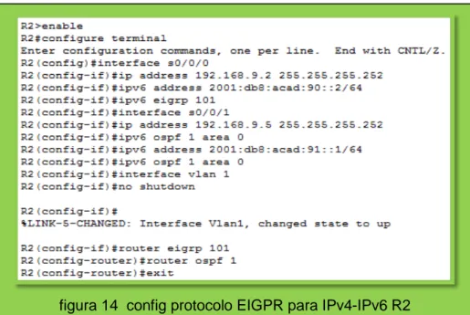
8. Realizar la configuración del protocolo EIGRP para IPv4 como IPv6. Configurar la interfaz F0/0 de R1 y la conexión entre R1 y R2 para EIGRP con el sistema autónomo 101. Asegúrese de que el resumen automático está desactivado.
R1#enable
R1#configure terminal
Enter configuration commands, one per line. End with CNTL/Z. R1(config)#ipv6 unicast-routing
R1(config)#router eigrp 101
R1(config-router) #no auto-summary R1(config-router) #interface s0/0/0
R1(config-if) #ip address 192.168.9.1 255.255.255.252 R1(config-if) #ipv6 address 2001:db8:acad:90::1/64 R1(config-if) #ipv6 eigrp 101
R1(config-if) #interface s0/0/1 R1(config-if) #no shutdown
R2>enable
R2#configure terminal
Enter configuration commands, one per line. End with CNTL/Z. R2(config)#interface s0/0/0
R2(config-if) #ip address 192.168.9.2 255.255.255.252 R2(config-if) #ipv6 address 2001:db8:acad:90::2/64 R2(config-if) #ipv6 eigrp 101
R2(config-if) #interface s0/0/1
R2(config-if) #ip address 192.168.9.5 255.255.255.252 R2(config-if) #ipv6 ospf 1 area 0
R2(config-if) #ipv6 address 2001:db8:acad:91::1/64 R2(config-if) #ipv6 ospf 1 area 0
R2(config-if) #interface vlan 1 R2(config-if) #no shutdown R2(config-if) #router eigrp 101
22 R2(config-router) #router ospf 1
R2(config-router) #exit
9. Configurar las interfaces pasivas para EIGRP según sea apropiado.
R1>enable
R1#configure terminal
Enter configuration commands, one per line. End with CNTL/Z. R1(config)#router eigrp 101
R1(config-router) #passive-interface g0/0
figura 14 config protocolo EIGPR para IPv4-IPv6 R2
23
10. En R2, configurar la redistribución mutua entre OSPF y EIGRP para IPv4 e IPv6. Asignar métricas apropiadas cuando sea necesario.
R2(config)#router ospf 1
R2(config-router) #redistribute eigrp 101 subnets R2(config-router) #exit
R2(config)#router eigrp 101
R2(config-router) #redistribute ospf 1 metric 1000 100 255 1 1500 R2(config-router) #exit
11. En R2, de hacer publicidad de la ruta 192.168.3.0/24 a R1 mediante una lista de distribución y ACL.
R2(config)#router ospf 1
R2(config-router) #redistribute eigrp 101 subnets R2(config-router) #exit
R2(config)#router eigrp 101
R2(config-router) #redistribute ospf 1 metric 1000 100 255 1 1500 R2(config-router) #exit
R2(config)#ip access-list standard ospfl-filter
R2(config-std-nacl) #remark used with dlist to filter ospf 1 routes R2(config-std-nacl) #deny 192.168.3.0 0.0.0.255
R2(config-std-nacl) #permit any R2(config-std-nacl) #exit
R2(config)#router eigrp 101 R2(config-router) #exit
24
Parte 2: Verificar conectividad de red y control de la trayectoria.
a. Registrar las tablas de enrutamiento en cada uno de los Routers, acorde con los parámetros de configuración establecidos en el escenario propuesto.
figura 17 publicidad en ruta R2
25
b. Verificar comunicación entre Routers mediante el comando ping y traceroute
figura 19 show ip route R2
figura 20 show ip route R3
figura 21 show ip interface brief R1
26
c. Verificar que las rutas filtradas no están presentes en las tablas de enrutamiento de los Routers correctas.
d. Verificar que las rutas filtradas no están presentes en las tablas de enrutamiento de los Routers correctas.
figura 22 ping R1
figura 23 show access-lists R2
27
ESCENARIO 2
Una empresa de comunicaciones presenta una estructura Core acorde a la topología de red, en donde el estudiante será el administrador de la red, el cual deberá configurar e interconectar entre sí cada uno de los dispositivos que forman parte del escenario, acorde con los lineamientos establecidos para el direccionamiento IP, etherchannels, VLANs y demás aspectos que forman parte del escenario propuesto.
Topología de red
ILUSTRACIÓN 3 ESCENARIO 2
28
Parte 1: Configurar la red de acuerdo con las especificaciones.
a. Apagar todas las interfaces en cada switch.
Switch>enable Switch#conf t
Enter configuration commands, one per line. End with CNTL/Z. Switch(config)#interface range f0/6-12
Switch(config-if-range)#shutdown
Switch#enable Switch#conf t
Enter configuration commands, one per line. End with CNTL/Z. Switch(config)#interface range f0/6-12
Switch(config-if-range)#shutdown
Switch>enable Switch#conf t
Enter configuration commands, one per line. End with CNTL/Z. Switch(config)#interface range f0/6-12
Switch(config-if-range)#shutdown
Switch>enable Switch#conf t
Enter configuration commands, one per line. End with CNTL/Z. Switch(config)#interface range f0/6-12
Switch(config-if-range)#shutdown
29
b. Asignar un nombre a cada switch acorde al escenario establecido.
Switch#enable Switch#configure terminal Switch(config)#hostname ALS1 ALS1(config)#exit Switch#enable Switch#configure terminal Switch(config)#hostname DLS1 DLS1(config)#exit Switch#enable Switch#configure terminal Switch(config)#hostname DLS2 DLS2(config)#exit Switch>enable Switch#configure terminal Switch(config)#hostname ALS2 ALS2(config)#exit
c. Configurar los puertos troncales y Port-channels tal como se muestra en el diagrama.
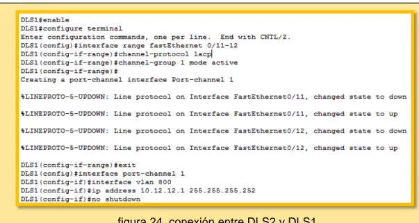
1) La conexión entre DLS1 y DLS2 será un EtherChannel capa-3 utilizando LACP. Para DLS1 se utilizará la dirección IP 10.12.12.1/30 y para DLS2 utilizará 10.12.12.2/30.
DLS1#enable
DLS1#configure terminal
DLS1(config)#interface range fastEthernet 0/11-12 DLS1(config-if-range) #channel-protocol lacp
DLS1(config-if-range) #channel-group 1 mode active DLS1(config-if-range) #exit
DLS1(config)#interface port-channel 1 DLS1(config-if) #interface vlan 800
30 DLS2>enable
DLS2#configure terminal
DLS2(config)#interface range fastEthernet 0/11-12 DLS2(config-if-range) #channel-protocol lacp
DLS2(config-if-range) #channel-group 1 mode active DLS2(config-if-range) #
DLS2(config-if-range) #exit
DLS2(config)#interface port-channel 1 DLS2(config-if) #interface vlan 800
DLS2(config-if) #ip address 10.12.12.2 255.255.255.252
figura 24 conexión entre DLS2 y DLS1
31
2) Los Port-channels en las interfaces Fa0/7 y Fa0/8 utilizarán LACP.
DLS1>enable
DLS1#configure terminal
DLS1(config)#interface range fastEthernet 0/7-8 DLS1(config-if-range) #channel-protocol lacp
DLS1(config-if-range) #channel-group 2 mode active DLS1(config-if-range) #no shutdown
DLS2>enable
DLS2#configure terminal
DLS2(config)#interface range fastEthernet 0/7-8 DLS2(config-if-range) #channel-protocol lacp
DLS2(config-if-range) #channel-group 2 mode active DLS2(config-if-range) #no shutdown
figura 26 port-channels Fa0/7 y Fa0/8 DLS1
32 ALS1>enable
ALS1#configure terminal
ALS1(config)#interface range fastEthernet 0/7-8 ALS1(config-if-range) #channel-protocol lacp
ALS1(config-if-range) #channel-group 2 mode active ALS1(config-if-range) #no shutdown
ALS2#enable
ALS2#configure terminal
ALS2(config)#interface range fastEthernet 0/7-8 ALS2(config-if-range) #channel-protocol lacp
ALS2(config-if-range) #channel-group 2 mode active ALS2(config-if-range) #no shutdown
figura 28 port-channels Fa0/7 y Fa0/8 ALS1
33
3) Los Port-channels en las interfaces F0/9 y fa0/10 utilizará PAgP.
DLS1>enable
DLS1#configure terminal
DLS1(config)#interface range fastEthernet 0/9-10 DLS1(config-if-range) #channel-protocol pagp DLS1(config-if-range) #channel-group 2 mode auto DLS1(config-if-range) #no shutdown
DLS2>enable
DLS2#configure terminal
DLS2(config)#interface range fastEthernet 0/9-10 DLS2(config-if-range) #channel-protocol pagp DLS2(config-if-range) #channel-group 2 mode auto DLS2(config-if-range) #no shutdown
figura 30 port-channels Fa0/9 y Fa0/10 DLS1
34 ALS1>enable
ALS1#configure terminal
ALS1(config)#interface range fastEthernet 0/9-10 ALS1(config-if-range) #channel-protocol pagp ALS1(config-if-range) #channel-group 2 mode auto ALS1(config-if-range) #no shutdown
ALS2>enable
ALS2#configure terminal
ALS2(config)#interface range fastEthernet 0/9-10 ALS2(config-if-range) #channel-protocol pagp ALS2(config-if-range) #channel-group 2 mode auto ALS2(config-if-range) #no shutdown
figura 32 port-channels Fa0/9 y Fa0/10 ALS1
35
4) Todos los puertos troncales serán asignados a la VLAN 800 como la VLAN nativa
DLS1>enable
DLS1#configure terminal
DLS1(config)#interface range fastEthernet 0/11-12 DLS1(config-if-range) #no switchport mode access DLS1(config-if-range) #switchport trunk native vlan 800 DLS1(config-if-range) #exit
DLS1(config)#interface range fastEthernet 0/7-8 DLS1(config-if-range) #no switchport mode access DLS1(config-if-range) #switchport trunk native vlan 800 DLS1(config-if-range) #exit
DLS1(config)#interface range fastEthernet 0/9-10 DLS1(config-if-range) #no switchport mode access DLS1(config-if-range) #no shutdown
36
d. Configurar DLS1, ALS1, y ALS2 para utilizar VTP versión 3
1) Utilizar el nombre de dominio UNAD con la contraseña cisco123 2) Configurar DLS1 como servidor principal para las VLAN.
3) Configurar ALS1 y ALS2 como clientes VTP.
DLS1#enable DLS1#conf t
DLS1(config)#vtp mode server DLS1(config)#vtp domain UNAD DLS1(config)#vtp password cisco123
figura 35 VLAN 800 VLAN nativa DLS1
37
e. Configurar en el servidor principal las siguientes VLAN:
TABLA 1 SERVIDOR VLAN
Número de Nombre de Número de Nombre de
8 NATIVA 434 ESTACIONAM
1 EJECUTIVO 123 MANTENIMIE
2 HUESPEDE 1010 VOZ
1 VIDEONET 3456 ADMINISTRA
DLS1(config-vlan)#name NATIVA DLS1(config-vlan)#exit DLS1(config)#vlan 12 DLS1(config-vlan)#name EJECUTIVOS DLS1(config-vlan)#exit DLS1(config)#vlan 234 DLS1(config-vlan)#name HUESPEDES DLS1(config-vlan)#exit DLS1(config)#vlan 1111 DLS1(config)#vlan 434 DLS1(config-vlan)#name ESTACIONAMIENTO DLS1(config-vlan)#exit DLS1(config)#vlan 123 DLS1(config-vlan)#name MANTENIMIENTO DLS1(config-vlan)#EXIT DLS1(config)#vlan 1010 DLS1(config)#vlan 3456
f. En DLS1, suspender la VLAN 434.
g. Configurar DLS2 en modo VTP transparente VTP utilizando VTP versión 2, y configurar en DLS2 las mismas VLAN que en DLS1.
h. Suspender VLAN 434 en DLS2.
DLS1(config)#vlan 434
38
i. En DLS2, crear VLAN 567 con el nombre de CONTABILIDAD. La VLAN de CONTABILIDAD no podrá estar disponible en cualquier otro Switch de la red.
DLS2>enable
DLS2#configure terminal DLS2(config)#vlan 567
DLS2(config-vlan)#name CONTABILIDAD DLS2(config-vlan)#exit
j. Configurar DLS1 como Spanning tree root para las VLAN 1, 12, 434, 800, 1010, 1111 y 3456 y como raíz secundaria para las VLAN 123 y 234.
DLS1#configure terminal
DLS1(config)#spanning-tree vlan 1,12,434,800,1010,1111,3456 root primary DLS1(config)#spanning-tree vlan 123,234 root secondary
figura 37 suspender VLAN 434 DLS1
figura 38 crear VLAN 567 DLS2
39
k. Configurar DLS2 como Spanning tree root para las VLAN 123 y 234 y como una raíz secundaria para las VLAN 12, 434, 800, 1010, 1111 y 3456.
DLS2#enable
DLS2#configure terminal
DLS2(config)#spanning-tree vlan 123,234 root primary
DLS2(config)#spanning-tree vlan 12,434,800,1111,3456 root secondary
l. Configurar todos los puertos como troncales de tal forma que solamente las VLAN que se han creado se les permitirá circular a través de estos puertos.
m. Configurar las siguientes interfaces como puertos de acceso, asignados a las VLAN de la siguiente manera:
TABLA 2 INTERFACE VLAN
Inter f
DLS1 DLS2 ALS1 A
LS
Interfaz Fa0/6 3456 12, 123, 23
Interfaz Fa0/15 1111 1111 1111 11
Interfaces F0 /16-18 567
DLS1#enable
DLS1#configure terminal
DLS1(config)#interface fastethernet 0/6 DLS1(config-if)#switch trunk native vlan 3456 DLS1(config-if)#exit
DLS1(config)#interface fastethernet 0/15 DLS1(config-if)#switch trunk native vlan 1111 DLS1(config-if)#exit
40 DLS2>enable
DLS2#configure terminal
DLS2(config)#interface fastethernet 0/6 DLS2(config-if)#switch trunk native vlan 12 DLS2(config-if)#switch trunk native vlan 1010 DLS2(config-if)#exit
DLS2(config)#interface fastethernet 0/15 DLS2(config-if)#switch trunk native vlan 1111 DLS2(config-if)#exit
DLS2(config)#interface range fastethernet 0/16-18 DLS2(config-if-range)#switch trunk native vlan 567 DLS2(config-if-range)#exit
figura 41 config VLAN DLS1
41 ALS1>enable
ALS1#configure terminal
ALS1(config)#interface fastEthernet 0/6 ALS1(config-if)#switchport mode trunk
ALS1(config-if)#switchport trunk native vlan 234 ALS1(config-if)#exit
ALS1(config)#interface fastEthernet 0/15
ALS1(config-if)#switchport trunk native vlan 1111 ALS1(config-if)#exit
ALS1(config)#interface fastEthernet 0/6 ALS1(config-if)#switchport mode trunk
ALS1(config-if)#switchport trunk native vlan 123 ALS1(config-if)#switchport trunk native vlan 1010 ALS1(config-if)#exit
ALS1(config)#interface fastEthernet 0/15
ALS1(config-if)#switchport trunk native vlan 1111 ALS1(config-if)#exit
Part 2: conectividad de red de prueba y las opciones configuradas.
a. Verificar la existencia de las VLAN correctas en todos los switches y la asignación de puertos troncales y de acceso
42
43
b. Verificar que el EtherChannel entre DLS1 y ALS1 está configurado correctamente
c. Verificar la configuración de Spanning tree entre DLS1 o DLS2 para cada VLAN.
FIGURA 46 SHOW VLANDLS1
44
45
CONCLUSIONES
• Aunque el inicio no fue nada fácil por aprender a configurar en cisco, puedo decir que fui adquiriendo habilidades a lo largo del curso que me fue más fácil entender el funcionamiento a tal punto de interconectar configurar todo lo que tiene que ver con la topología de red.
• Lo aprendido en este diplomado será esencial en muestras vidas profesionales sin depender si somos ingenieros de comunicación, electrónicos o industriales, los sistemas cumplen un lugar extremamente importante en cualquier sector económico y el saber programar nos hace más competentes a la hora de buscar empleos con grandes industrias.
46
BIBLIOGRAFIA
Froom, R., Frahim, E. (2015). CISCO Press (Ed). Switch Fundamentals Review. Implementing Cisco IP Switched Networks (SWITCH) Foundation Learning Guide CCNP SWITCH 300-115. Recuperado de
https://1drv.ms/b/s!AmIJYei-NT1IlnWR0hoMxgBNv1CJ
Macfarlane, J. (2014). Network Routing Basics: Understanding IP Routing in Cisco
Systems. Recuperado
de http://bibliotecavirtual.unad.edu.co:2048/login?url=http://search.ebscohost.com/l ogin.aspx?direct=true&db=e000xww&AN=158227&lang=es&site=ehost-live
Froom, R., Frahim, E. (2015). CISCO Press (Ed). Network Management. Implementing Cisco IP Switched Networks (SWITCH) Foundation Learning Guide CCNP SWITCH 300-115. Recuperado de https://1drv.ms/b/s!AmIJYei-NT1IlnWR0hoMxgBNv1CJ
Este Objeto Virtual de Aprendizaje, titulado Vídeo - Switch CISCO Security Management, tiene como objetivo, orientar al estudiante sobre mecanismos de seguridad y administración en Switches.
UNAD (2015). Switch CISCO Security Management [OVA]. Recuperado de https://1drv.ms/u/s!AmIJYei-NT1IlyVeVJCCezJ2QE5c
Teare, D., Vachon B., Graziani, R. (2015). CISCO Press (Ed). Path Control Implementation. Implementing Cisco IP Routing (ROUTE) Foundation Learning Guide CCNP ROUTE 300-101. Recuperado de https://1drv.ms/b/s!AmIJYei-NT1IlnMfy2rhPZHwEoWx
Froom, R., Frahim, E. (2015). CISCO Press (Ed). Switch Fundamentals Review. Implementing Cisco IP Switched Networks (SWITCH) Foundation Learning Guide CCNP SWITCH 300-115. Recuperado de