Integrated Electronic System for Ultrasonic
Structural Health Monitoring
P. M. MONJE*, L. CASADO*, G. ARANGUREN*,
V. COKONAJ**, E. BARRERA*** and M. RUIZ***
ABSTRACT
A fully integrated on-board electronic system that can perform in-situ structural health monitoring (SHM) of aircraft’s structures using specifically designed equipment for SHM based on guided wave ultrasonic method or Lamb waves’ method is introduced. This equipment is called Phased Array Monitoring for Enhanced Life Assessment (PAMELA III) and is an essential part of overall PAMELA SHM™ system. PAMELA III can generate any kind of excitation signals, acquire the response signals that propagate throughout the structure being tested, and perform the signal processing for damage detection directly on the structure without need to send the huge amount of raw signals but only the final SHM maps. It monitors the structure by means of an array of integrated Phased Array (PhA) transducers preferably bonded onto the host structure. The PAMELA III hardware for SHM mapping has been designed, built and subjected to laboratory tests, using aluminum and CFRP structures. The 12 channel system has been designed to be low weight (265 grams only), to have a small form factor, to be directly mounted above the integrated PhA transducers without need for cables and to be EMI protected so that the equipment can be taken on board an aircraft to perform required SHM analyses by use of embedded SHM algorithms. Moreover, the autonomous, automatic and on real-time working procedure makes it suitable for the avionic field, sending the corresponding alerts, maps and reports to external equipment.
*Pedro María Monje, Luciano Casado and Gerardo Aranguren are with the Electronics Design Group of the University of the Basque Country, 48013 Bilbao, Spain.
**Valerijan Cokonaj is with AERnnova Engineering Solutions Ibérica S.A, Madrid, Spain, within the Structural Integrity Department of the R&D Section, SHM group.
***Eduardo Barrera and Mariano Ruiz are with the Instrumentation and Applied Acoustic Research Group of the Technical University of Madrid (UPM), Madrid, Spain. 6th European Workshop on
INTRODUCTION
Structural health monitoring (SHM) systems have emerged to fulfill the need to have control over the integrity of any structure for its full lifetime and
to improve nondestructive evaluation and testing (NDE/T) techniques. In the case of the aerospace industry, an aircraft’s structural integrity is one of the most critical concerns. It must be also taken into account that aircraft maintenance costs are a large part of the budget for an airline.
Several methods are available to ensure the structural integrity of an aircraft [1], such as visual inspection, eddy current foil sensors (ECFS), comparative vacuum monitoring (CVM), microwave antennas, fiber bragg gratings (FBG), magnetic
particles, acoustic-emission, acousto-ultrasonics, guided wave ultrasonics, electromechanical impedance or radiographic inspection. However, most of these techniques cannot be automated or carried on in real time because it is necessary to take the structure off of the aircraft to perform the structural inspections. Therefore, if an autonomous SHM system is to be designed, it a method must be selected which does not put any obstacle for its implementation. One of the techniques that presents itself as a viable solution is the guided wave ultrasonics method [2], based on guided ultrasonics waves, also known as Lamb waves. Currently, SHM systems based on Lamb waves require expensive and bulky equipment to work, such as oscilloscopes or signal generators. It is not feasible to take dedicated commercial ultrasonic equipment on-board because of its weight, volume, and energy consumption.
With the objective of designing an SHM system for an on-board use, the Electronics Design Group of the University of the Basque Country, the Instrumentation and Applied Acoustic Research Group of the Technical University of Madrid under the direction of AERnnova Engineering Solutions Ibérica S.A started a research and development line which name is Phased Array Monitoring for Enhanced Life Assessment (PAMELA). During more than five years, all of the entities of the research and development program have developed a SHM system based on the guided wave ultrasonic method. The result of this project is the PAMELA SHM™ system, which integrates the necessary hardware, software, and an integrated array of piezoelectric transducers (PhA) to improve the operational safety of aerospace structures and to reduce an aircraft’s structural maintenance costs. Moreover, PAMELA SHM™ can also be used to test other kind of structures, after proper adaptations, including submarines, buildings, bridges, pressure vessels, oil tanks, and pipelines.
In this paper, the design, analysis techniques, implementation and laboratory tests performed with the PAMELA III hardware are described.
PAMELA SYSTEM OVERVIEW
attenuation and wave reflection are sensed to detect and locate damage in the material [3].
Architecture of PAMELA Hardware
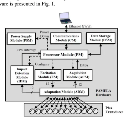
The general diagram of the integrated electronic architecture inside PAMELA hardware is presented in Fig. 1.
Figure 1. General diagram of the advanced electronic architecture inside PAMELA. Dashed lines represent control and configuration signals, while straight lines indicate the path of the rest of the signals: excitation signals, acquisition signals, hardware interrupts, etc.
The Processor Module configures and controls the rest of the modules in PAMELA III and performs the signal processing required for each analysis algorithm. It is based on an embedded PowerPC processor, which is inside a field programmable gate array (FPGA) device from Xilinx Inc.
The Excitation Module generates the excitation signal for each of the twelve output channels. It has been designed to generate signals of configurable shape, frequency, amplitude, phase and delay for each excitation channel. The flexibility of this module allows each channel to be excited independently from the others. The shape of the excitation signals is easily synthesized for any desired signal. The main characteristics of the excitation signals are shown in Table 1.
Table 1.Configurable characteristics of the excitation signals.
Characteristic Value
Number of Channels 12 independent or combined
Frequency range 30 kHz to 1 MHz
Voltage range 0 V to 40 V peak-to-peak
Shape of signal Sinusoidal, triangular, Hanning-windowed
Delay
between signals 0 to 2500 nanoseconds (10 ns step)
The Adaptation Module receives the excitation signals and adapts each of them to the corresponding piezoelectric transducer. It connects the Excitation Module and the Acquisition Module with the piezoelectric transducers, providing a full-duplex connection between them, with electric isolation and protections from short- duration high-voltage signals.
The Acquisition Module amplifies, filters, and samples the analog waveforms received by the transducers and converts the resulting samples into digital numeric values. The samples are stored in the Data Storage Module using a direct memory access engine.
The Impact Detection Module listens on each channel for a signal of greater amplitude than the detection level and then generates a hardware interrupt.
The Communications Module communicates the architecture with external equipment through an Ethernet link or a wireless connectivity link. The option for a wireless connectivity offers new possibilities [4].
System Assembly
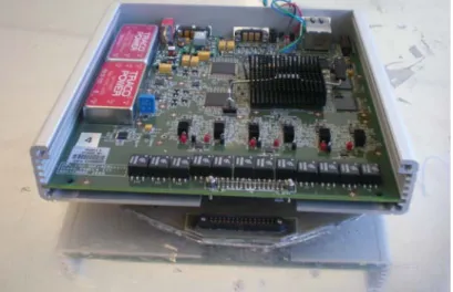
The electronic system has been designed, manufactured, tested and it has been enclosed into an aluminum box. The fully assembled system is shown in Fig. 2 Its overall dimensions are 165 mm by 162 mm and by 30 mm. PAMELA III weights 688 g (box included). The weight of the electronic part of the system is only 265 g, which makes the SHM system suitable for a direct installation on aerospace structures, having it on-board an aircraft using an alternate light-weight box. This system is patent pending [5].
Figure 2. PAMELA III hardware, with all its electronic and mechanical components inside the aluminum box, placed over the piezoelectric transducer adapter bonded to the structure in order to perform SHM tests.
ANALYSIS TECHNIQUES BY PAMELA SHM
Transducer integrity analysis: despite the advantages of the piezoelectric transducers, there are two major PZT failure modes of concern in field applications, transducer debonding and cracking [7], which can change the response and shift the resonant frequency of the PZT. This analysis, based on the measurement of the admittance of each transducer in a wide range of frequencies and its comparison with a healthy admittance, allows to auto-check the transducer integrity.
Round-Robin (Simple and Fast): this technique consists of alternately changing the excitation channel among the twelve available transducers, starting in the first transducer and cycling through the rest of them, acquiring signals with the twelve transducers. Each single test lasts two milliseconds. By advanced signal processing techniques and reconstruction algorithms, 2D or 3D images of the structure can be generated, indicating any changes found in the structure. In Fast Round-Robin test mode, only twelve steps are necessary to acquire the entire 12 by 12 matrix, while in the Simple Round-Robin 144 steps are necessary.
Transmitter Beamforming: the beamforming technique is based on a directional transmission of ultrasonic signals using an array of transducers. This spatial selectivity is achieved exciting all the elements of the array with the excitation signal, but delaying each excitation signal a certain amount of time from one transducer to another, increasing the damage detection capability. The 10 nanoseconds spacing in time between samples in the excitation signals allows PAMELA III to perform several tests to cover up to 400 angles of the structure under test.
Time reversal (Simple and Round Robin): time reversal is a technique for focusing waves in an inhomogeneous medium [8]. During the time reversal process, the elements of the array are excited and the ultrasonic signals are then acquired and sent inverted to the medium. According to the time reversal concept, the signal that is sent reversed to the medium must be identical to the signal that is acquired after the first transmission. If this is not the case, there is clear evidence that there is a non-linearity in the structure (i.e., a defect). The flexibility of the electronic system makes it suitable to generate twelve different signals for each piezoelectric transducer simultaneously.
Transmitter Focusing: this test mode [9], first measures the backscattered signals of a first signal transmission by a single element of the linear array of piezoelectric transducers. By changing the time delays between the excitation signals, in successive iterations the transmitted signal transmission can be focusing of on a specific defect or structure section of interest in order to improve the response and the final image resolution.
Near-field algorithms: the algorithms explained until now are normally used for far- field damage detection. However, techniques such as a variation on the beamforming technique, known as adaptive beamforming or triangulation algorithms can be successfully used for near-field analysis. The flexibility and independence of the twelve excitation signals allows to divide the phased array transducer in two sub- arrays and to calculate the distance to the defect in near-field range.
Pitch-catch with multiple SHM systems: in PAMELA SHM, one or more PAMELA
Passive Mode: this technique is useful for impact detection, leakage detection, mass losses detection, etc. In this mode, the PAMELA hardware listens on all the transducers for a signal of greater amplitude than a threshold level previously set. After an impact, the SHM system stores an amount of samples acquired before and after the impact for post-processing, which allows an analysis of the evolution of the impact.
TEST RESULTS
There are two possible scenarios where PAMELA can perform structural health monitoring: laboratory and on-board an aircraft. In a laboratory setting, an operator configures PAMELA III for a test using a human-machine interface (HMI) that runs on an external computer connected through an Ethernet link. After the configuration is complete, the operator starts a test. The SHM system excites the structure and acquires the necessary signals, which are then sent to the external computer using the Ethernet link. The external computer does the signal processing to determine the structural integrity.
In collaboration with Aeronautical Technologies Centre (CTA), a series of laboratory tests were carried out using the PAMELA SHM™ system. Using aluminum and carbon fiber–reinforced polymer (CFRP) specimens, one-axis traction static loading tests were performed. Linear arrays of twelve piezoelectric transducers per inspection sector were bonded to the structures using several transducer adapters and an epoxy adhesive. In the SHM tests, the specimens were subjected to alternately changing traction loading and were monitored in situ for structural integrity.
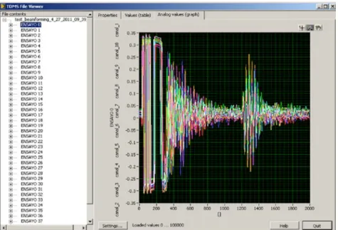
During the laboratory tests, for each loading condition, the resulting signal responses were acquired and then post-processed to obtain the corresponding SHM maps for the detection and comparison of the load effects. An application programmed in LabVIEW was used to represent the matrices of digitized ultrasonic response signals. An example of this test is presented in Fig. 3.
The methodology differs when PAMELA SHM™ system is on-board an aircraft. The SHM system is configured prior to placement with a program that performs periodic SHM tests. When on board, the system periodically tests the structure and sends only the result of each structural integrity analysis to external equipment. This is the ultimate scenario in which PAMELA SHM™ will perform the structural health monitoring.
CONCLUSION
An ultrasonic SHM electronic system called PAMELA III, which is the key component of the PAMELA SHM™ system, has been designed, built and subjected to laboratory tests. Its low weight and small size makes it suitable for the aerospace applications.
The flexibility of the hardware allows the generation of excitation signals of configurable shape, frequency and amplitude, which can be transmitted through one to twelve transducers. PAMELA III hardware can perform multiple SHM algorithms: transmitter beamforming, transducer integrity analysis, round-robin, time reversal near-field algorithms, analysis using multiple PAMELA SHM™ systems, etc.
Laboratory tests were conducted using metallic and CFRP structures to which linear arrays of twelve piezoelectric transducers were bonded. The signals acquired during the tests were digitized and sent to a laptop, where meaningful representations, post- processing and SHM analyses were performed. It was demonstrated that the system works correctly for structural health monitoring purposes.
By using PAMELA SHM™ system, autonomous, automatic and on real-time inspections can be performed and both the safety maintenance and the maintenance costs reduction can be accomplished.
ACKNOWLEDGEMENTS
The authors are grateful to the research projects AIRHEM II (Basque Government Etortek program), ICARO and SINTONIA (Spanish Government CENIT programs) for funding and supporting this research.
REFERENCES
[1] H. Speckmann and R. Henrich, "Structural Health Monitoring (SHM): Overview on Technologies Under Development," AIRBUS, 2004.
[2] V. Giurgiutiu, A. Zagrai and J. Bao, "Embedded Active Sensors for In-situ Structural Health Monitoring of Thin Wall Structures," Journal of Pressure Vessel Technology, vol. 124, pp. 293-302, 2002.
[3] J. R. Wait, G. Park, H. Sohn and C. R. Farrar. (2004, Plate damage identification using wave propagation and impedance methods . SPIE Proceedings Series 5394pp. 53-65.
[4] E. Barrera M. Ruiz, V. Cokonaj, G. Aranguren, L. Casado and P. M. Monje, "Structural Health Monitoring Network System with Wireless Communications inside Closed Aerospace Structures.". European Workshop on Structural Health Monitoring, 2012.
[6] V. Cokonaj, "Integrated Phased Array Transducer for On-Board Structural Health Monitoring." European Workshop on Structural Health Monitoring, 2012.
[7] S. J. Lee and H. Sohn. 2010, "Piezoelectric transducer self-diagnosis under changing environmental and structural conditions". IEEE Transactions on UFFC 57(9), pp. 2017-2027. [8] N. Chakroun, M. Fink and F. Wu. Time reversal processing in ultrasonic non-destructive
testing. Ultrasonics, Ferroelectrics and Frequency Control, IEEE Transactions on 42(6), pp. 1087-1098