External force estimation for telerobotics without force
sensor
Enrique del Sol 1,2, Prithvi Pagala 1, Ryan King 2, Manuel Ferre 1 1
Center of Automation and Robotics , Madrid , Spain {ps.pagala, m.ferre}@upm.es 2
Oxford Technologies Ltd, Abingdon, United Kingdom enrique.delsol@oxfordtechnologies.co.uk
Abstract. This paper establishes an approach to external force estimation
through the use of a mathematical model and current sensing, without employing a force/torque sensor. The advantages and need for force feedback have been well established in the field of telerobotics. This paper presents the requirement for sensorless force estimation and comparative results between a force sensor and the presented approach using an industrial robot. The approach presents not only a cost effective solution but also a solution for force sensing in hazardous environments, especially ionizing radiation prone environments where the dose rates limit the use of sensing equipment. The paper also discusses the applica-tions and advantages presented by this work in various fields.
Keywords: Industrial robot, sensorless, remote handling, force feedback,
mas-ter-slave system
1
Introduction
In teleoperation a human operator manipulates master device, and a slave device fol-lows the motion while manipulating in a remote environment. Providing the operator with various information regarding the remote environment like position, orientation, contact, load, forces and others; improves the task performance and the operator un-derstanding of the environment. This information can be viewed on display screens [1] but, it is more intuitive when provided directly, by reflecting the measured parameters like positions and torques to the master haptic device. When the operator is interacting with the slave with a haptic master then the operator is said to be kinesthetically cou-pled to the environment. The task being performed is said to be bilateral controlled teleoperation [2], [3]. The continued advances in these various fields of control, communications, haptic systems and others have made possible to have an integrated robotic master slave system that it is able to aid the human operator in effective task execution.
hazards on the master and slave sides of the teleoperation. Transparency is said to be achieved when the human operator interacting with the master device feels as if present in the remote environment. Which means that, the human operator movements are mimicked by the slave in the remote environment and the reaction force from the remote environment is applied to the operator [4].
Haptic devices used in telerobotics are force exerting mechatronic designs to ensure the human operator experiences an immersive interaction with the remote environment. Generally, kinesthetic haptic interfaces not only exert forces to the operator, but behave as bidirectional channel to exchange forces and interactions. In recent years, haptic interfaces have advanced in various interfaces and towards cost effectiveness, like the creation of commercialized equipment [5]. They have been used for several applica-tions in different fields such as telerobotics [6-7], medical surgery [8-10] and others. Dissimilar master-slave systems have been coupled with the use of scaling and other adaptation [11] methods.
This paper will be focussed on hazardous environments with ionising radiation as they present critical need for robot deployments to reduce human intervention. These environments are primarily nuclear facilities and large scientific facilities focused on nuclear research.
Nuclear facilities [12] have continuously used robot deployments since the first developments carried out by Ray Goertz for the U.S. Atomic Energy Commission [13]. Large scientific experiments like CERN (European Organization for Nuclear Research) [14] and JET (Joint European Torus) [15],[16] are also deploying telerobotic solutions in sections where the ionising radiation and hazardous conditions make it difficult or impede human intervention. Ionising radiation hazard depends on the location, dose rates and time elapsed. Some of the robot deployments at CERN for maintenance are, the autonomous source storage robots in the ISOLDE facility [17], the teleoperated TIM robot [18] and Mantis mobile platform [19]. While at CERN and JET complete remote handling solutions for all the tasks were not considered during the design phase but, at ITER (International Thermonuclear Experimental Reactor) [20][21] it is crucial to have complete remote handling solutions due to the hazardous environment.
been adapted for teleoperation tasks. This has been done previously by attaching high proficiency force and torque sensors in the robotic end-effectors [22] for teleoperation tasks and during a shared control study [23].
Two requirements to further increase the use of teleoperated robots during mainte-nance of hazardous facilities are presented in section 2. Section 3 explains the hy-pothesis and the preliminary results of the approach. Section 4 details the setup used when applying this research on an industrial robot. In section 5 the mathematical model and the approach is explained. Results of the approach from the industrial robot are compared with the results from force torque sensor are presented in section 6 and in section 7 conclusions and future developments are presented.
2
Requirements
Towards reducing human intervention and as low as reasonable achievable (ALARA) safety measures, more remote handling solutions are explored. A working problem and need has been seen in large scientific facilities where remote handling under ionizing radiation is necessary.
2.1 Force estimation for teleoperation of industrial robots
2.2 Force sensors in radioactive environments
Another need for such a force sensorless system is, to be able to obtain force feedback information without the need of designing new force sensors due requirement of size and application in the remote environment. The findings summarized by Keith E. Holbert et al. in [29] during their performance study of commercial off-the-shelf mi-croelectromechanical (MEMS) systems sensors in a radioactive hazardous environ-ment, shows the limitations imposed by radioactivity over pressure transducers based on MEMS technology. Hence, depending on the different hazardous environments and robot tasks there is a need to redesign sensors due to size and environment require-ments. An example of which is the development of hard-rad ATI force sensor used in the AREVA recycling plant [25] robot deployment.
The ability to have force information from the remote environment without a force/torque sensor is beneficial in terms of understanding the remote environments force interactions. Along with no additional large cost, size and development time to adapt the robot with a force senor. Therefore, these requirements are the motivation behind the presented approach of force estimation without the use of force sensor for application in telerobotics.
Fig. 1. Force-Position control algorithm.
3
Hypothesis
As the forces and torques applied on the master are proportional to those applied to the slave in a bilateral control using force channel, the estimation of the robot end effector torques and forces can be accomplished by means of modelling the robot dynamics. Equation (1) describes the relation between forces and torques on the end effector and joint torques on the robot and equation (2) is the well-known equation of robot dy-namics.
Where,
τm: vector of motor torques exerted in each joint. J: is the robot jacobian.
: is the vector of forces and torques ejected in the robot end effector and expressed in the base coordinates system.
D: is the robot inertia matrix. H: is the Coriolis forces vector. C: is the gravity forces vector. τ : is the friction torques vector.
τext: is the external torques on each joint produced by external forces on the end ef-fector.
τm=D q ·q+H q, q · q+C q +τf q +τext (2)
By combining (1) and (2) the external forces at the tip result on (3).
Text=(J T
)-1· τm-D q ·q-H q, q · q-C q -τf q (3)
We hypothesise that in electric motors torque can be correctly estimated with equation (4). Based on the current amplitude of each actuator and the mathematical model it is possible to determine the external forces excreted on a robot with multiple degrees of freedom.
τm=Ke ·Ia·G (4)
Where,
Ke : is the motor torque constant in [N/A]. Ia: is the current amplitude in [A]. G: is the gear ratio for each joint.
If the motor currents are sinusoidal the instantaneous amplitude of the waveform can be calculated with the following expression (5) detailed in [30] where ia and ib are the phase a and b instantaneous currents respectively.
Ia= ia
√2·sin(atan -√3ia 2ib+ia)
(5)
3.1 Preliminary Setup.
Fig. 2 shows the preliminary setup used to verify the first hypothesis. It was composed by:
• 1x Aerotech® S-50-86 AC motor.
• 2x TH3A Hall effect current sensors
• 1x RWT410 series manufactured by Torquesense®
• 1x pulley setup with different weights available.
The current sensors were calibrated and placed in shielding to avoid electromagnetic interference and noise. The test rig used in this setup is able to support the motor in a free axis movement as well as allow the weight lifting of several weights with a pulley of 32 mm in radius.
Fig. 2. AC Motor test bench with torque transducer
Fig. 3. Single DOF torque experiment.
-0.6 -0.4 -0.2 0 0.2 0.4 0.6 0.8 1
0 500 1000 1500 2000
T
o
rq
u
e
[N
m
]
Time [ms]
Torque with current calculation [Nm]
3.2 Preliminary results
Tests were carried out in the mentioned test rig, lifting varying weights by means of coupling the pulley directly to the motor axis. Fig. 3 corresponding to the external torque calculated via measuring the two phase currents of the motor and applying the expression in (5) and the measurement with the torque meter inserted between load and motor axis. The calculated torque is proportional to its correspondent torque meter curve and in this case has less error than the torque meter. It indicates the precision acquired with this method as the torque calculation is performed using the instanta-neous current data acquisition. The small delay between the two curves is caused by the time that the cabling weight takes in acquiring the necessary tension to lift the weight.
4
Setup
The experimental setup is composed by the following elements:
• 1 x ABB IRB 2400-16 industrial manipulator, Fig 4.
• 1 x ABB SC4+ robot controller able to interface with RS422.
• 1 x NI-USB 6212, 16-Bit resolution, 400 kS/s.
• 1 x EMI shielded measurement box specifically designed for this purpose shown in Fig. 4.
• 1 x Force/Torque sensor, ATI, Gamma SI-130-10.
The ABB IRB 2400-16 is an industrial robot with a payload of 20 kg and a reach of 1.55 m. It is equipped with 6 axis driven by PMSM actuators.
In order to measure the instantaneous current consumption of each actuator an EMI shielded measurement system was designed to capture the outgoing current from the robot controller to the manipulator. This measurement board is composed by 12 Hall Effect sensors, two for each motor. The current sensors used on this experiment are the inexpensive TH3A for joints 1, 3, 4, 5 and 6 and TH5A for joint 2 with nominal input currents of 3 and 5 A respectively. The output signal of each sensor was sampled at 1 KHz by means of the NI-USB 6212.
5
EXPERIMENT DESIGN
5.1 Dynamic modelling
The Newton-Euler or Lagrangian method is typically used to derive the dynamic equations of kinematic chains of rigid bodies [31]. Both approaches yield the equation described in. (6), which is basically (2) without the friction and external forces terms. τ is an Nx1 vector expressing the joint torque vector necessary to move a robot with N dof with the dynamics described by the right part of the equation.
τ=D q ·q+H q, q · q+C q (6)
The barycentric parameters [32] or the modified Newton-Euler method [31] can be used to yield a model of the form:
τ= f (q, q, q) (7)
It is linear in the inertial parameters. Particularizing for a unique point in a certain trajectory that forms results into the following equation:
τi=Ai·øi (8)
Where is an n x 1 vector, Αi· is an n x 10n matrix and ø is an n x 1 vector. For linear models it is possible to apply a parameter estimation by least mean squares by stacking the equation (8) with P data points [33] .and obtaining the vector form (9):
τ=A·ø (9)
With:
τ= :·
and Α= A1
: ·
Αp
(10)
ø= ATA -1ATτ (11)
Unfortunately it is not possible to always apply simple least squares estimation since ATA is not invertible due the loss of rank from restricted degrees of freedom at the proximal links and the inability to measure the forces and torques in every direction [33]. Two main methods are used to cope with the loss of rank, parameters elimination and damped least squares. The parameters elimination technique discards the non-identifiable parameters indicated by zero or small singular values of the regressor matrix. This procedure is not necessary when having an initial parameter estimation ø0 obtained from the CAD model or by different means. The damped least squares leads to a solution by:
ø=(ATA+λ2I)-1ATτ̃ (12)
Where λ is the damping factor and τ̃=τ-Aø0. The damping factor modifies the singular values and cancels out the effect of very small values. The initial solution will be perturbed over the normal least-squares solution.
5.2 Slave characterization and parameters determination
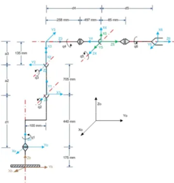
A dynamic robot model which relates robot motion to joint torques, describes the rigid-body motion of the robot. This model includes the joint friction composed by Coulomb and viscous friction in the joints and inertial parameters for each link. The inertial parameters are the link mass, centre of mass coordinates and inertias with respect to each link frame: m, cx, cy, cz, Ixx, Iyy, Izz, Ixy, Ixz, Iyz. As this a priori in-formation was not provided by the manufacturer, the parameters were calculated by using a CAD 3D model representing the robot. A uniform density solid virtual robot was created in order to estimate the mass of each link, the centre of gravity coordinates with respect each joint origin and the inertia matrix. These results are shown in Table 1. The DH parameters were established based on the diagram of Fig. 5.
Tests were performed in order to estimate the torque constant for each joint as they are not usually provided by the manufacturer. The procedure defined in order to esti-mate these constants was general for every joint but with some differences due the various configurations presented and the non-equal gravity effect on each one. De-termining the torque constant allowed calculating the motor torque in real time.
Fig. 5. ABB IRB 2400 links diagram.
Table 1. LINKS PARAMETERS FOR LINKS 1 TO 6
Link 1 Link 2 Link 3 Link 4 Link 5 Link 6
M [kg] 146.1 44.52 46.02 17.89 0.978 0.012
Cx [m] -69.52 -383.4 95.14 0.301 0.956 0.015
Cy[m] -169.6 -50.11 -14.9 198.4 0.039 -0.01
Cz[m] -20.7 -0.493 -14.3 -1.01 -0.24 0.032
Ixx[kg·m2] 11.84 0.242 1.043 0.519 -0.06 -0.002
Iyy[kg·m2] 6.571 1.784 3.408 0.043 -0.95 -0.06
Izz[kg·m2] 9.875 1.758 2.726 0.510 -0.89 -0.03
Ixy[kg·m2] -2.746 -0.058 0.119 3E-4 0.036 0.01
Ixz[kg·m2] -0.51 -0.005 0.329 4E-5 -0.23 -0.1
Table 2. POSES USED FOR EXPERIMENT ON FIG. 6
Pose Q1 [deg] Q2 [deg] Q3 [deg] Q4 [deg] Q5 [deg] Q6 [deg]
A -94.2 10.6 22.7 19.9 12.4 81.4
B -93.5 25.5 26.8 25.6 8.4 75.9
6
RESULTS
The results presented in Fig. 6 evaluate the model accuracy when calculating the ex-ternal perpendicular force by using (3) for the trajectory defined between pose A and B and returning to A, shortened for sake of clarity. These points are presented in Table 2. The force prediction error is small except when the velocity changes its sense, as it was expected due the uncertainty of the friction curve at low speeds and the low frequency available for the positional feedback due the controller limitations in comparison with the rate of the actuators current readings.
Fig. 6. Model validation based on external force estimation by experiment.
An increase in the error of the torque calculations when the motor changes its sense has also been detected which is produced by the phase order change of the currents which creates a non-sinusoidal transitional wave prejudicial for the amplitude calcula-tion described by equacalcula-tion (5).
It has been found than perpendicular forces can be calculated with an average error of 2.47 kg which means 12.35% of the payload. Hence, validating the proposed ap-proach and differentiating it from the state of art presented.
-200 -150 -100 -50 0 50 100
0 2000 4000 6000 8000 10000 12000
F
o
rc
e
[N
]
Time [ms]
7
Conclusion
The facilities where maintainability and measuring tasks have to be executed in a radioactive or hazardous environment will likely increase the application of remote handling solutions due to the safety measures like ALARA, reducing the human in-teraction with hazardous environments. Force feedback would be essential to perform remote handling and maintenance. Since backdrivable slaves and torque sensors are not cost-effective an alternative approach has been proposed which estimates the external forces and torques with an acceptable level of accuracy by using the robot model and current information. This method does not require either any modification of the robot or additional wiring but only current sensing at the controller output. It can be em-ployed not only as a substitution of the conventional sensors but also as a redundant solution when other methods are preferred. The applications of the proposed method are not limited to hazardous environments but can also be applied to robot solutions where it is difficult to add a sensor at the end-effectors, like medical telesurgery, and where there is a need to design environment and size specific force sensors. This ap-proach can be extended to other robot manipulators and future work would focus on implementing it on light weight and hydraulic manipulators.
Acknowledgements. This research project has been supported by a Marie Curie Early
Stage Initial Training Network Fellowship of the European Community's Seventh Framework Program under contract number PITN-GA-2010-264336-PURESAFE.
References
1. Kotoku, T., A predictive display with force feedback and its application to remote manipulation system with transmission time delay, in lEEE/RSJ International Conference on Intelligent Robots and Systems, vol. 1, pp. 239–246, IEEE Press, New York (1992). 2. Hecht D., Reiner M., Sensory dominance in combinations of audio, visual and haptic
stimuli, Experimental brain research, vol. 193, no. 2, pp. 307–314 (2009).
3. Ernst M. O., Banks M.S., Humans integrate visual and haptic information in a statistically optimal fashion, Nature, vol. 415, no. 6870, pp. 429–433 (2002).
4. Yokokohji Y., Yoshikawa T., Bilateral control of master-slave manipulators for ideal kinesthetic coupling-formulation and experiment, in IEEE Transactions on Robotics and Automation, vol. 10, no. 5, pp. 605–620 (1994).
5. Salisbury J.K., Srinivasan M.A., “Phantom-based haptic interaction with virtual objects,” IEEE Computer Graphics and Applications, vol. 17, no. 5, pp. 6–10, IEEE Press, New York (1997).
6. Škorc G., Zapušek S., Čas J., Šafarič R., “Virtual user interface for the remote control of a nano-robotic cell using a haptic-device,” Strojniški vestnik Journal of Mechanical Engineering, vol. 56, no. 7–8, pp. 423–435 (2010).
7. Peer A., Buss M., A new admittance-type haptic interface for bimanual manipulations, , IEEE/ASME Transactions on Mechatronics, vol. 13, no. 4, pp. 416–428 (2008).
9. Okamura A.M., Methods for haptic feedback in teleoperated robot-assisted surgery, Industrial Robot: An International Journal, vol. 31, no. 6, pp. 499–508 (2004).
10. McMahan W., Gewirtz J., Tool contact acceleration feedback for telerobotic surgery, IEEE Haptics, vol. 4, no. 3, pp. 210–220, IEEE Press, New York (2011).
11. Colgate J.E., Power and impedance scaling in bilateral manipulation, IEEE International Conference on. Robotics and Automation, pp. 2292–2297, IEEE Press, New York (1991). 12. Nof S.Y., Handbook of industrial robotics, vol. 1. Wiley (1999).
13. Hokayem P.F., Spong M.W., Bilateral teleoperation: An historical survey, Automatica, vol. 42, no. 12, pp. 2035–2057 (2006).
14. Horne R.A., Coin A.Y., Pusenius M., Hendseth S., Kallevik V., Extended tele-robotic activities at CERN (1991).
15. Rolfe A.C., Brown P., Carter P., Cusack R., Gaberscik A., Galbiati L., Haist B., Horn R., Irving M,, Locke D., A report on the first remote handling operations at JET, Fusion engineering and design, vol. 46, no. 2, pp. 299–306 (1999).
16. David O., Loving A.B., Palmer J.D., Ciattaglia S., Friconneau J.P., Operational experience feedback in JET Remote Handling, Fusion engineering and design, vol. 75, pp. 519–523 (2005).
17. Kugler E., The ISOLDE facility, Hyperfine Interactions, vol. 129, no. 1–4, pp. 23–42 (2000).
18. Kershaw K, Remote Inspection , Measurement and Handling Applied to Maintenance and Operation at CERN Introduction, October (2012).
19. Horne R A , Lohmann K D , Coull L , Coin A Y , Therville A , Lips R , Desrozier M, MANTIS: a compact mobile remote handling system for accelerator halls and tunnels, in ANS Meeting on Remote Systems and Robotics in Hostile Environments, vol. 30 (1978). 20. Honda T., Hattori Y., Holloway C., Martin E., Matsumoto Y., Matsunobu T., Suzuki T.,
Tesini A., Baulo V., Haange R., Remote handling systems for ITER, Fusion engineering and design, vol. 63, pp. 507–518 (2002).
21. Tesini A., Palmer J., The ITER remote maintenance system, Fusion Engineering and Design, vol. 83, no. 7, pp. 810–816 (2008).
22. Lee J.K., Kim K., Park B.S., Yoon J.S., Force-reflecting servo-manipulators for remote handling task in a radioactive environment, in Control, International Conference on Automation and Systems, ICCAS ’07., 2007, pp. 1025–1028 (2007).
23. Dumora J., Geffard F., Bidard C, Brouillet T., Fraisse P., “Experimental study on haptic communication of a human in a shared human-robot collaborative task,” IEEE/RSJ International Conference on Intelligent Robots and Systems (IROS), pp. 5137–5144, IEEE Press, New York (2012).
24. Fischer P., Daniel R., Siva K.V., Specification and design of input devices for teleoperation, in IEEE International Conference on Robotics and Automation, Proceedings., pp. 540–545 vol.1. (1990).
25. Piolain G., Geffard F., Coudray A., Garrec P., Thro J.F., Perrot Y., Dedicated and standard industrial robots used as force-feedback telemaintenance remote devices at the areva recycling plant, 1st International Conference on Applied Robotics for the Power Industry (CARPI), pp. 1–6 (2010).
26. Ferre M., Buss M., Aracil R., Melchiorri C., Balaguer C., Advances in Telerobotics. Springer Berlin / Heidelberg (2007).
28. Nakao M., Kouhei O., Miyachi K., A robust decentralized joint control, in IEEE Proceedings on Robotics and Automation, pp. 326–331, IEEE Press, New York (1987). 29. Holbert K.E., Heger A.S., McCready S.S., Performance of Commercial Off-the-Shelf
Microelectromechanical Systems Sensors in a Pulsed Reactor Environment, IEEE Data Workshop in Radiation Effects (REDW), p. 8, IEEE Press, New York (2010).
30. Del Sol E., Scott R., King R., A sensorless virtual slave control scheme for Kinematically dissimilar master-slave teleoperation, in HOTLAB (2012).
31. Atkeson C.G., An C.H., Hollerbach J.M., Estimation of inertial parameters of manipulator loads and links, The International Journal of Robotics Research, vol. 5, no. 3, pp. 101–119 (1986).
32. Fisette P., Raucent B., Samin J.C., Minimal dynamic characterization of tree-like multibody systems, Nonlinear Dynamics, vol. 9, no. 1–2, pp. 165–184 (1996).