TítuloCombined biological and physicochemical waste gas cleaning techniques
39
0
0
Texto completo
(2) Introduction The environmental effects of air pollutants are a matter of increasing regulatory concern. Volatile organic and inorganic compounds are common air pollutants emitted from a variety of both mobile and stationary sources. The emissions of VOCs to the atmosphere originate from breathing and loading losses from storage tanks, venting of process vessels, leaks from piping and equipments, contaminated wastewater streams, and heat exchanger systems, among others.[ 1 ] Apart from this, industries such as petrochemicals, refineries, plastic processing and moulding, carbon black, rubber processing, vegetable and fish processing units, animal farming and rendering units, coke production and polymeric resin producing units also contribute to substantial amount of VOC emissions.[ 2 , 3 ] VICs such as hydrogen sulphide are commonly found in polluted air at wastewater treatment plants, among others. From an environmental point of view, it is necessary to limit and control the emissions of pollutants to the atmosphere as they affect climate change, growth of plants and overall the health of human beings and all forms of life. Deteriorating air quality has contributed to stringent regulations all over the world and meeting regulatory standards in process industries has been a major challenge for environmental engineers and plant managers. Besides reducing the emissions at their source, various techniques are available for the treatment of waste-gas streams loaded with VICs and VOCs. Sometimes, combinations of techniques may be required to reduce the pollutant levels below legal limits. A large number of treatment options exist for the removal of volatile pollutants from industrial waste-gases, which are primarily selected based on the characteristics of the gas-phase pollutants and on the composition of the waste-gas, gas-flow rate, and other factors such as safety or economic considerations.[ 4 ] Biological treatment systems such as biofilters and biotrickling filters appear to be both cost-competitive and highly efficient for the complete mineralization of relatively low concentrations of pollutants (<5 g/m3), to harmless end-products such as H2O and CO2, at ambient temperature.[ 1 , 4 – 7 ] In field situations, industrial effluents may show variable loading patterns and several gas-phase bioreactors can tolerate moderate shock-loads. However, when subjected to a sudden high shock-load, the microorganisms generally find it extremely difficult to tolerate such situation over a long period of time. For such situation and conditions where the treatment system is expected to receive varying levels of shock-loads, some reports have suggested the addition of a nonbiological technique as the first treatment step followed by a bioreactor in order to reduce high loads down to levels that can easily be handled in the bioreactor. Physical and chemical air pollution control processes (destructive or recovery based) have.
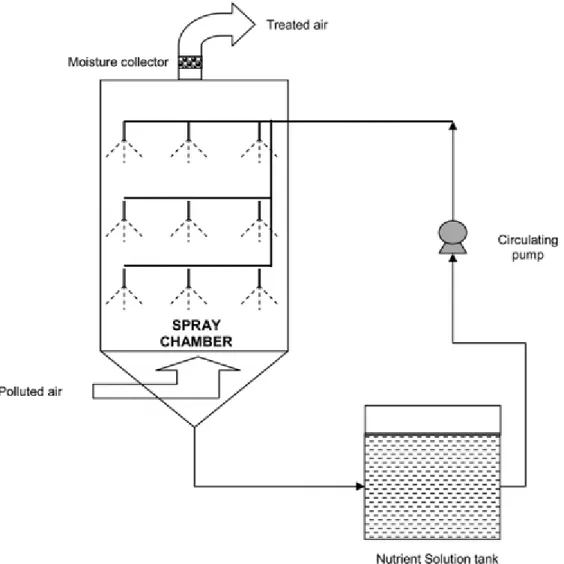
(3) proven to be effective for handling exceedingly high concentrations of volatile pollutants in the waste-gas stream.[ 7 ] Physicochemical waste-gas treatment techniques collectively include processes such as absorption, adsorption, condensation, thermal and catalytic incineration, membrane separation, and several advanced oxidation processes (AOPs). This paper provides a general overview of some of the most commonly used physical, chemical and biological treatment techniques in industrial situations. The advantages of coupling a non-biological process with a bioprocess are discussed. Physicochemical waste-gas treatment techniques The most common non-biological treatment technologies are absorption, adsorption, and oxidation, that can be used as stand-alone processes or in combination with bioreactors. These different technologies, used as stand-alone processes, will briefly be reviewed hereafter. Absorption Absorption is a diffusional mass transfer operation by which soluble gaseous pollutants are removed by direct dissolution in a solvent liquid.[ 8 ] The driving force for mass transfer is the concentration difference of the solute between the gaseous and liquid phases. The water-soluble VOCs present in the waste-gases are physically transferred to the liquid phase. A key variable of this process is the selection of a suitable liquid absorbent, and for waste-gas treatment applications, water and low volatile organic liquids are commonly used as the absorbing liquid.[ 9 ] For hydrophobic VOCs, as for example α-pinene, water cannot be used, and literature suggests the use of water-oil emulsions, water-solid suspensions, and high-boiling absorbents.[ 4 ] According to Heymes et al.,[ 4 ] an organic absorbent should possess the following characteristics: (i) high absorption capacity for a wide variety of VOCs, (ii) low viscosity and high diffusion coefficient, which can control the absorption kinetics, (iii) low vapour pressure in order to reduce loss of absorbent by stripping and to prevent additional air pollution problems, (iv) easy availability and low cost, and (v) no toxicity nor fire or explosion risks. Some typical examples of organic absorbents include the following: vegetable oils, mineral oil, diesel oil, alkylpthalates, alkyladipates, polyethylene glycol, dimethyl ethers, amongst others. With regard to reactor configurations for performing absorption, the most commonly used reactor types are the packed and plate columns, spray chambers (Figure 1) and towers, cyclonic spray chambers and combinations of spray and packed chambers, jet and venturi scrubbers. In order to facilitate rapid mass transfer, absorption towers should be designed to provide a large liquid to vapour contact area. This can be.
(4) achieved, for example, by selecting optimized tower packings or liquid atomization systems.[ 1 ] The predominant choice for waste-gas treatment is the packed scrubber, using either water and/or chemicals.[ 7 ]. Fig. 1 Example of an absorption column: spray chamber. Water scrubbing in packed towers Countercurrent operation is most common in packed scrubbers for air pollution control. In a countercurrent water scrubber, the waste-gas is fed through the bottom of an absorption column, contacting a counterflowing stream of water. The column is filled with a packing material in order to have a high contact surface area between the liquid and the waste-gas. The treated gas leaves the top of the column, while the liquid collected at the bottom contains the pollutants. The liquid stream is transferred to a stripper, where water is regenerated by desorption with a counter flow of air. Water scrubbing requires large amounts of water, so single pass scrubbing is neither very economic nor an eco-friendly option. Hence, in most cases regenerative absorption is preferred.[ 10 ].
(5) Chemical scrubbing Chemical absorption involves the reversible formation of weak chemical bonds, i.e., intermolecular interactions, between the pollutants and the solvent. Regeneration of the solvent, therefore, involves breaking of these bonds and correspondingly, a relatively high energy input.[ 11 ] The most commonly used chemicals are highly oxidative by nature (examples: ozone, hydrogen peroxide, and sodium hypochlorite), but some of these chemicals have their own practical limitations. For instance, when hypochlorite is used for removing amines, it cannot only oxidize the pollutants, but also chlorinate the compounds, releasing chlorine gas and chlorinated amines that will have to be eliminated by placing additional sulphuric acid scrubbers.[ 12 ] Adsorption Adsorption is a surface phenomenon in which the gas-phase pollutants are brought into contact with a suitable solid adsorbent. This technique is widely used to clean waste-gas streams containing odours, VOCs and other airborne pollutants appearing at relatively low to moderate concentrations. Generally, this process is classified as either physical adsorption or chemisorption, based on the interactions between the adsorbate and adsorbent. Physical adsorption can be further classified as pressure swing adsorption (PSA) and temperature swing adsorption (TSA). For VOC control, physical adsorption has been found to play a more significant role than chemisorption. It occurs when organic molecules are held on the surfaces and in the pores of the adsorbent by weak van der Waals forces of attraction, characterized by low heat of adsorption and by the fact that adsorption equilibrium is reversible.[ 13 ] The solid can thus be regenerated (desorption) and reused. The most commonly used adsorbent for waste-gas treatment is activated carbon. The adsorption capacity of a typical activated carbon process for a given pollutant is represented by an adsorption isotherm representing the amount of volatile compound adsorbed at constant temperature. After achieving the breakthrough point, the pollutant should be released (desorption) from the surface in order to reuse the carbon, which is commonly done with steam. Some useful adsorption models are given below: 1. Langmuir model for homogenous monolayer adsorption. 2. Freundlich model for heterogeneous surface and intermolecular interactions.
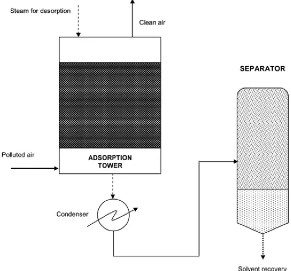
(6) 3. Brunauer-Emmett-Teller. (BET). model. for. multilayer. adsorption. Activated carbon is widely recognized as a highly efficient adsorbent because it provides a large surface area, which is the result of its vast infrastructure of pores, micro-pores and micro-pores within micro-pores.[ 1 ] A typical activated carbon based VOC removal system together with a solvent recovery plant is shown in Figure 2. It consists of a fixed bed of activated carbon through which the waste-gas is passed. The gas-phase pollutants get adsorbed onto the surface of the activated carbon, until the carbon reaches its breakthrough. During the solvent recovery step, the activated carbon is heated with steam, and the pollutant is released and flushed away by steam.. Fig. 2 Schematic of an adsorption column with a solvent recovery system. After breakthrough is attained, the adsorbent is regenerated by steam..
(7) The mixture of steam and solvent can then be condensed by a cooling system, and subsequently separated by gravity decanting. In practical situations, multiple carbon beds are used in series. The saturated bed can be kept off-line during the regeneration process. Moisture content, retention ability, pressure, concentration, type of adsorbent and desorption method used are some of the critical parameters that decide the efficiency of an adsorption process. During the design of fixed bed adsorption units, the two most critical dimensions to be taken care of are the diameter of the adsorber and the depth of the adsorbent bed. Gas-phase pollutants such as acetone, benzene, toluene, xylenes, TCE, hydrogen sulphide, mercaptans, sulphur dioxide, and many others, have successfully been removed by this technique.[ 14 , 15 ] Pressure swing adsorption In pressure swing adsorption, adsorption of gas-phase pollutants takes place at elevated pressure and the material is regenerated by reducing the pressure and subsequent application of a light vacuum. However, this process requires a pretreatment step in order to remove water vapor present in the inlet stream. This is normally done by adsorption onto impregnated activated carbon, followed by an increase in the temperature between 60°C and 90°C. Water vapor competes with the VOCs in the emission stream for adsorption sites on the carbon surface. Additionally, the presence of water can destroy the structure of the adsorbent. Photocatalytic oxidation The destruction of volatile pollutants, such as VOCs, by photocatalytic means is one of the emerging purification techniques for both wastewater and waste-gases, due to its versatility and high effectiveness at low temperatures. Heterogeneous photocatalysis is one such process that is based on the photonic excitation of a catalyst (mostly TiO2) at the appropriate wavelength of an incident UV light. In general, organic compounds have a redox potential at higher energy than the valence band edge of common semiconductor oxides and therefore can act as an electron donor yielding a radical cation, which can further react with H2O or O2. The chemistry occurring at the surface of a photo-excited semiconductor is based on the radical formed from O2, H2O and electron rich organic compounds..
(8) Fig. 3 Mechanism of photocatalytic oxidation.. This mechanism primarily depends on the characteristics of irradiation, mass of photocatalyst, and concentration of the reactants.[ 16 ] Most of the recent studies on the removal of VOCs have chosen TiO2 as the catalyst for the following reasons: (i) inexpensive and easily available, (ii) operation at room temperature and pressure, and (iii) effective degradation of VOCs into CO2 and H2O.[ 17 – 20 ] Moreover, recent studies have shown greater removal of VOCs by a combined O3/TiO2/UV process, as excess ozone molecules could scavenge hydroxyl radicals produced from the excitation of TiO2 by UV radiation.[ 21 , 22 ] Large scale installations for air purification by TiO2 photocatalysis have been built by Trojan Technologies in North America and by the United Technologies of Connecticut, among others, as reported elsewhere.[ 16 ] These systems were designed to strip hydrocarbons from soil or groundwater and photo-catalytically irradiate (treat) them to acceptable limits. However, because of the poor yield of photon utilization, the treatment of gaseous VOCs may require reactor sizes that are prohibitive in some cases. Though this technique has been reported to be simple, robust and flexible, its operating cost arises mainly from the UV lamps and the corresponding electrical consumptions. Mechanism of photocatalytic oxidation The mechanism of photocatalytic oxidation is illustrated in Figure 3. The generation of electron-hole pairs caused by the excitation of the catalyst (TiO2) with UV light is crucial for the photocatalytic oxidation process.[ 23 ] Semiconductors like TiO2 are characterized by a filled valence band and an empty conduction band, and the energy difference between the lowest energy level of the conduction band and the highest.
(9) energy level of the valence band is called the band-gap energy. This corresponds to the minimum energy of light required to make the semiconductor (photocatalyst) electrically conductive. When a photon's energy, hν, exceeds the energy of the band gap, an electron, e−, is promoted from the valence band to the conduction band, leaving a hole, h+, behind.[ 24 ] The electrons and holes photo-generate in the bulk of the semiconductor and move to the particle surface (Figure 3), where electrons reduce the electron acceptors such as molecular oxygen, and holes oxidize the electron donors including adsorbed water or hydroxide anion to give hydroxyl radical.[ 25 , 26 ] Photocatalysis over TiO2 is initiated by the absorption of a photon with energy equal to or greater than the band gap of the semiconductor (3.2 eV for TiO2), producing electron-hole (e−/h+) pairs. The adsorbed oxygen molecules accept the electrons preventing hole-electron recombination. At the surface of the coated catalyst, the hydroxyl radicals (OH*) drive the chemical reaction by attacking oxidizable contaminants, producing a progressive breaking of molecules yielding CO2, H2O, mineral acids and other end-products. The sequence of redox reactions involved in a PCO is summarized here: 1. Excitation by high-energy wavelength light to generate pair of electron (e−) and hole (h+): TiO2+hυ→TiO2(h++e−) 2. Oxidation of adsorbed TiO2(h+)+H2O→OH*+H+. water. molecules. to. give. hydroxyl. radicals:. produce. hydroxyl. radicals:. 3. Reduction of oxygen to super oxide: 4. Generation of an oxidizing agent: O− 2+2H++3e−→H2O2 5. Dissociation. of. the. oxidizing. agent. to. 6. Recombination of electron and hole releases heat: TiO2(e−)+TiO2(h+)→Heat 7. Overall gas-phase photochemical reaction: acids.
(10) Table 1 Photocatalytic oxidation products of gas-phase pollutants in photocatalytic reactors. Pollutants Degradation products References Trichloroethylene, Methylene chloride, carbon tetrachloride [23, 83] Perchloroethylene Phosgene, CO2 and dichloroaceyl chloride Benzene Phenol, hydroquinone, benzoquinone, and [84] malonic acid Toluene Benzaldehyde, benzene, benzyl alcohol, [32, 85] formic acid, acetic acid, CO2 and trace amounts of benzoic acid and phenol Formaldehyde Formic acid [86] α-Pinene Pinocamphone, 3-hydroxyl - α-pinene, [35] acetaldehyde, acetone, formic acid, acetic acid, glycolic acid, propionic acid, propanedioic acid, CO, and CO2 2-Propanol Acetone, mesityl oxide, CO2 and H2O [87, 88] Formation of intermediate products In an ideal photocatalytic oxidation reaction, the gas-phase pollutant is completely oxidized, mainly to carbon dioxide and water. However, in many cases, complete mineralization of the gas-phase pollutant to innocuous end-products is not possible, and other toxic and problematic by-products are identified during the course of photocatalytic reactions.[ 27 , 28 ] For instance, during the photocatalytic oxidation of dichloromethane, the following intermediates were observed: chloroform, carbon tetrachloride, phosgene, methyl chloride, CO and CO2.[ 29 ] For chlorinated compounds like trichloroethylene, the formation of partial oxidation products such as phosgene, dichloroacetyl chloride, monochloroacetyl chloride, dichloroacetic acid and monochloroacetic acid has been reported in the literature.[ 27 ] Some of these compounds are more toxic than the parent compound. According to Fan and Yates,[ 30 ] dichloroacetyl chloride is a reaction intermediate that can undergo continued photooxidation to generate phosgene (COCl2), CO and HCl, according to the following equation:. This reaction is expected based on the relatively strong UV absorptivity and high extinction coefficient (103/m.s) of dichloroacetyl chloride, and its weak acylchloride bonds.[ 31 ] Phosgene can react with TiO2 surfaces in the dark to undergo hydrolysis to yield HCl and CO2, and this surface hydrolysis reaction principally depends on the amount of adsorbed water or hydroxyl groups present in the TiO2 surface.[ 27 ].
(11) Mohseni[ 28 ] reported phosgene and chloroform as the two major quantified byproducts, along with trace amounts of carbon tetrachloride during the photocatalytic degradation of TCE in an annular type photoreactor using a low-pressure mercury lamp emitting UV at either 254 (light intensity – 7.3 to 9.8 × 10⁻³ W/cm2) or 365 nm (light intensity – 3.5 × 10⁻³ W/cm2), at a retention time of 0.5 s. A mass balance calculation revealed that 0.4 and 0.6 mol of phosgene were formed for every mole of TCE removed, indicating that about 25% of the carbon in the TCE molecule was converted to phosgene, a planar molecule and a highly toxic compound. In another study, toluene photooxidation was carried out in a cylindrical photoreactor by Augugliaro et al.[ 32 ], using TiO2 as the catalyst (BET surface area 4 m2/g), and illuminated with a 400 W medium pressure mercury lamp having a light intensity of 5 mW/cm2. Benzaldehyde, benzene, benzyl alcohol and traces of benzoic acid and phenol were identified as the oxidation products in that study. Other identified photocatalytic oxidation products of different gas-phase pollutants are summarized in Table 1. Assessing biodegradability and toxicity of intermediates It is clearly evident that toxic intermediates and easily biodegradable compounds, such as aldehydes, alcohols, or acids may be produced during photocatalytic oxidation, irrespective of the gas-phase pollutant (whether hydrophilic, hydrophobic or chlorinated organics), and it is important to evaluate or assess the biodegradability of these intermediates and by-products if one wants to develop adequate biological posttreatment options. Some well known water quality parameters such as biological oxygen demand, chemical oxygen demand, total organic carbon, and their ratios, BOD/COD and BOD/TOC, inhibition of oxygen consumption, dissolved organic carbon, amount of organic matter, assimilable organic compound (AOC), EC50 toxicity tests, amongst others, have frequently been used by researchers working on PCOs to estimate biodegradability.[ 33 – 35 ] Photocatalytic oxidation reactions will change the molecular structure of the parent compounds (gas-phase pollutants), and break them down into smaller molecules.[ 36 ] These smaller molecules or by-products of oxidation can be classified as either readily biodegradable compounds or poorly biodegradable compounds. In the former case, a typical high oxidation capacity process decomposes the target organic pollutant to smaller organic compounds having high oxidation states and higher biodegradability (example: oxalic and carboxylic acids), while in the latter case, low oxidation capacity processes can only partially decompose the parent organic pollutant resulting in byproducts having low oxidation states and high molecular weights..
(12) Fig. 4 Schematic of a biofilter.. Large values of BOD/COD ratios indicate high biodegradability of the compounds and a value of 0.3 is usually considered to be the cut-off point between non-biodegradability and biodegradability.[ 35 ] Chen et al.[ 35 ] carried out direct UV photodegradation experiments in a spiral quartz type photoreactor, using α-pinene as the model VOC. The intermediates were identified to be pinocamphone, 3-hydroxyl-α-pinene, acetaldehyde, acetone, formic acid, acetic acid, glycolic acid, propionic acid, and propanedioic acid, which were formed under different test conditions (in the presence of air or nitrogen with a relative humidity of 2–3% or 75–80%). The authors conducted toxicity tests on the unicellular green microalgae C. vulgaris and performed alga growth inhibition tests. It was observed that the BOD/COD ratio increased from 0.2 to 0.35 when experiments were performed in the presence of air, suggesting that these intermediates were more easily biodegradable than α-pinene. Results from inhibition tests showed that the inhibition decreased with an increase in the removal of α-pinene in the photoreactor. The inhibition ratio was 68% when α-pinene was used alone, while this ratio decreased to 24% when the intermediates were tested for their biodegradability. Al Momani and.
(13) Jarrah[ 34 ] collected gas-phase toluene oxidation intermediates in water impingers and measured the BOD, COD and dissolved organic carbon values of that water. The authors reported that high organic matter was present in the solar+O3 assisted process, and the average DOC, COD and BOD values for the solar+O3+TiO2 process were found to be 8 mg C/L, 18 mg O2/L, and 7 mg O2/L, respectively. Furthermore, the authors observed that the average biodegradability index was found to be 0.41 for the solar+O3+TiO2 system, indicating the suitability of a biological technique as a posttreatment option. Biological waste-gas treatment techniques Treatment of VOCs and VICs from industrial sources, such as emissions from point sources, is a relatively new application of bioreactor technologies. Biological waste-gas treatment systems have gained support as an effective, reliable, eco-friendly, simple and economical option in comparison to the different physical and chemical VOC removal technologies such as absorption, adsorption, thermal and catalytic incineration, and photocatalytic destruction.[ 3 , 7 , 37 ] Biological waste-gas treatment techniques explore the ability of microorganisms to destroy environmental contaminants present in waste-gases. The contaminants are often utilized by microorganisms as a source of carbon and energy. Not only organic but also inorganic volatile compounds may be effectively removed, although some of those pollutants (example: hydrogen sulphide) may require the presence of an additional carbon source..
(14) Fig. 5 Schematic of a biotrickling filter. The most commonly used bioreactor configurations in industrial waste-gas treatment are biofilters and biotrickling filters. For practical reasons, while choosing an appropriate treatment technique, focus is placed on the microbial ecology and its activity, operational and control requirements needed to ensure an optimal chemical and physical environment for mass transfer and biodegrada- tion of the pollutant in order to achieve high removal efficiencies.[ 38 ] In addition to this, reactor configurations such as air-lift bioreactors, spiral bioreactors, membrane bioreactors, two-liquid phase biotrickling filters, two-liquid phase suspended-growth bioreactors, monolith bioreactors, and rotating biological contactors have been tested experimentally at the laboratory- or pilot-scale for waste-gas treatment.[ 7 , 39 – 41 ] The following categories of industrial chemicals in waste-gases have been treated in different bioreactor configurations: (i) aliphatic compounds, (ii) aromatic hydrocarbons, (iii) chlorinated hydrocarbons, (iv) nitrogen containing carbon compounds, (v) sulphur containing carbon compounds, (vi) oxygenated carbon compounds, and (vii) inorganic compounds..
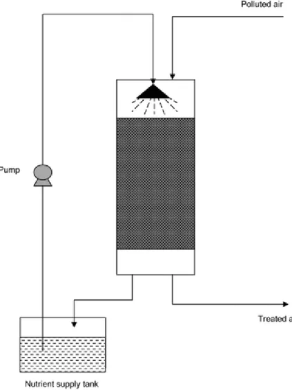
(15) Biofilters The design of conventional biofilters has varied and improved over the past sixty years, from simple open soil beds to closed systems equipped with automated control and on-line measurement devices. Biofiltration is typically an aerobic degradation process in which a contaminated air stream is passed through a porous packed medium that supports a thriving population of microorganisms (Fig. 4). Anaerobic biofiltration is, however, also possible. The principles governing this are similar to other common biofilm processes. The contaminant in the gas-phase is first absorbed from the air phase to the water of the biofilm interphase. Then, this contaminant diffuses through the biofilm to a consortium of well-acclimated microorganisms. The microorganisms play a major role in converting the pollutant into CO2, water and sometimes other endproducts (example: sulphur or sulphate from H2S). They generally obtain sufficient energy from the oxidation of the chemical, while utilizing it as a primary substrate via non-specific enzymes.. Fig. 6 Schematic of a bioscrubber with a scrubber and a bioreactor unit. In other cases, the pollutants may be degraded co-metabolically. The degree of treatment depends on the type and composition of the waste-gas stream, its watersolubility, activity of the microbes, media pH, temperature, moisture content of the filter bed, nutrient and O2 availability and other suitable conditions needed for aerobic biodegradation. Biofiltration has been considered economically advantageous to treat air streams containing low concentrations of organic contaminants at large flow rates.[ 7 , 42 , 43 ].
(16) A wide variety of both organic and inorganic compounds such as alcohols, aldehydes, ketones, hydrocarbons, carboxylic acids, H2S and NH3 have been treated in biofilters.[ 44 ] More complex constituents such as chlorinated organics can be handled as well, but at slower rates and their degradation may sometimes require the presence of a cometabolite. For example, dichloromethane was shown to be eliminated in a biofilter with 98% efficiency in the presence of toluene[ 45 ], although other studies have also reported the biodegradation of DCM as single carbon source.[ 46 ] Moreover, competitive/inhibitory effects between chemicals and microorganisms can play a vital role in the removal of pollutants in biofilters. Due to such complexities, removal rates for mixtures may need to be determined using case-by-case treatability studies. The removal of VOCs using fungi-inoculated biofilters was initiated recently. Fungi may show some advantages over bacterial cultures, especially for the treatment of hydrophobic VOCs, because of their ability to degrade the substrate under extreme environmental conditions of pH (2 to 7) or low water content. It was also hypothesized that the large surface area of hyphae provided by filamentous fungi would enhance absorption and transport of hydrophobic compounds from the gas-phase to the cell surface.[ 47 ] Recent developments in this field include: understanding pollutant degradation pathways, use of molecular profiling techniques to identify microbial community and its distribution within the biofilter, identifying interaction effects during the removal of pollutant mixture, modeling transient operating conditions (shock-loads), process modeling, and the development of sophisticated control systems for biofilters.. Fig. 7 Schematic of an adsorption column+biofilter used for flow equalization and handling periodic shock-loads..
(17) Biotrickling filters In biotrickling filters, the pollutant laden waste stream is passed over a microbial consortium immobilized on an inert support material having a high surface area (Figure 5). The process of gas absorption, liquid phase regeneration and subsequent degradation occurs simultaneously in one reactor configuration. A continuous stream of recirculating water containing essential nutrients for microbial growth is distributed over the filter bed. This water flows down as a thin film and wets the biofilm layer. The waste-gas stream passes through the trickling biofilter, either as co- or counter current flow to the liquid, and supplies the essential carbon source for microorganisms. Some factors affecting pollutant removal are: (i) composition and concentration of the waste-gas stream, (ii) structural configuration of the packing material, (iii) flow pattern, (iv) nutrient composition, (v) gas-flow rate or residence time, (vi) pH, and (vii) temperature.[ 48 ] Typical filter media can be inert materials such as ceramic or plastic structures, activated carbon, celite or mixtures of materials.[ 7 , 49 ] Biotrickling filters have been used successfully to treat compounds that produce acidic or alkaline metabolites such as halogenated hydrocarbons, H2S, NH3 and dichloromethane.[ 46 , 50 ] The metabolites generated from microbial degradation can be easily removed by the re-circulating liquid stream. In addition they are able to withstand high pollutant loadings due to high biomass concentrations.[ 51 ] Biotrickling filters have also proven to be highly efficient in handling mixtures of hydrophilic and hydrophobic VOCs, as they are able to maintain dominant species of both fungi and bacterial cultures within the same reactor configuration. López et al.[ 50 ] investigated the combined removal of H2S, methanol and α-pinene vapours in a single-stage biotrickling filter, at empty bed residence times of 38 and 26 s, and reported maximum elimination capacities of 191, 307 and 123 g/m3.h, for H2S, methanol and α-pinene, respectively. The main drawback of this system is the problem associated with mass transfer, especially for compounds that are hydrophobic. Biotrickling filters are effective for the treatment of gaseous compounds with an air/water partitioning coefficient of less than 0.1.[ 51 ] The other drawbacks include channelling, filter material degradation, high pressure drop, and the accumulation of excess biomass.[ 52 , 53 ] Several methods have been proposed in the literature to remove the accumulated biomass, and thereby reduce pressure drop: backwashing, air sparging, increasing the trickling rate of the medium, mechanical agitation, biological predation, and adopting improved operational modes.[ 41 , 54 , 55 ].
(18) Bioscrubbers (Absorption pre-treatment + bioreactor) A bioscrubber is a biological waste-gas treatment system consisting of two individual units, namely the scrubbing unit and the bioreactor unit (usually an activated sludge reactor). In the first-stage scrubber, the contaminants are absorbed by a continuously moving water phase, while in the bioreactor contaminants in water phase are degraded by aerobic microorganisms (Figure 6). The scrubbing liquid can also be continuously recycled after regeneration in the bioreactor unit. However, the degree of regeneration depends on the size of the bioreactor unit and the retention time of the scrubbing liquid.[ 12 ] The bioscrubbing process is easily controlled because pH, temperature, nutrient balance and removal of metabolic end-products can easily be altered in the water phase of the reactor.[ 56 ] Bioscrubbing systems have been used for the biodegradation of odorous compounds and some of the target industries are the following: rendering plants, livestock farming, public owned treatment works, food industries and foundries.. Fig. 8 Schematic of a two-stage reactor (UV photoreactor -or UV Photocatalytic reactor+biofilter) for handling periodic shock-loads. Gas-phase pollutants such as H2S, SO2 and highly water soluble compounds such as alcohols, aldehydes and fatty acids have successfully been removed using bioscrubbers. The important types of scrubbers are: (i) counter and co-current packed towers, (ii) cross flow packed towers, (iii) wet cyclones, (v) spray towers, and (vi) Venturi scrubbers.[ 57 ].
(19) Whaley et al.[ 58 ] treated isopropyl alcohol, acetone and heptane in a pilot-scale bioscrubber in a concentration range of 200–500 mg/m3 and observed removal efficiencies greater than 99%, two weeks after start-up. In a study aimed at removing odorous sulphur compounds from ventilation air in a wastewater treatment plant, Heist et al.[ 59 ] achieved oxidation rates of 155 mg/g.h at a pH of 9, for sulphur concentrations above 2 mg/l. Studies by Schippert[ 60 ], on the removal of mixtures of butyl glycols, n-butanol, ethyl glycol, isobutanol, xylene and methyl-isobutyl-ketone (MIBK) showed that xylene and MIBK were poorly removed (70%), compared to other VOCs (99%) in bioscrubbers. In general, the scrubbing liquid and vapour stream should be carefully selected, as they lose their cost efficiency for compounds having a Henry's coefficient > 0.01.[ 52 ] Typical superficial air velocities in bioscrubbers vary in the range of 0.5 to 2.5 m/s. Though bioscrubbing presents high potential for development because VOC transfer and biodegradation could be separately improved[ 61 ], they have not been used widely due to complex start-up procedure, high operational cost and sludge generation. If packed towers are used in the scrubbing unit, during the start-up or acclimation phase, microorganisms start to grow on the packing and form a biofilm, which would play a major role in affecting the performance of the scrubber. Hence, adequate care should be taken to avoid clogging of the scrubbing unit. However, recent advancements have been made in this system in order to optimize VOC mass transfer in the scrubber. Lalanne et al.[ 62 ] proposed a two-phase partitioning bioscrubber as a high performance biotechnology alternative for the treatment of waste-gases containing a mixture of oxygenated, aromatic and halogenated compounds. The addition of cutting oil (2.5 to 10 mass-%) to the water phase, according to the authors, changed the physical properties (density, gas solubility and gas diffusivity) of the liquid mixture, and the gas-liquid characteristics (droplet distribution inside the boundary layer, mass transfer mechanism, mass transfer coefficient and gas-liquid interfacial area), leading to a higher rate of transfer of the solute gas across the boundary layer. In that study, the total load applied to the bioscrubber was 852 g VOC/m3.h, while the liquid to gas (L/G) ratio was maintained at 0.0094. The authors reported steady state VOC removal efficiencies of 40–47% in the bioscrubber, and the addition of cutting oil did not affect the metabolic activity of the microorganisms in the biological reactor. In another study, a semi-industrial type scrubber fitted with atomizing spray nozzles was tested for the removal of 11 VOCs (methanol, acetone, methyl-ethyl-ketone, methylisobutyl-ketone, ethyl acetate, butyl acetate, toluene, ethylbenzene, xylene, 1,2dichloroethane, and dichloromethane) over a period of 13 months, using a nondefined washing liquid as the scrubbing medium.[ 63 ].
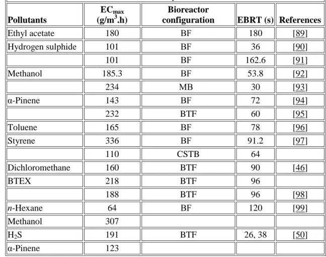
(20) That bioscrubber was started with a load of 852 g VOC/m3.h for 6 months, and the load was subsequently increased to 1704 g VOC/m3.h for 3 months, and then decreased to 426 g VOC/m3.h for 4 months. The authors reported removal efficiencies ranging from 35 to 50% during these phases of operation, and most of all the absorbed compounds were degraded in the bioreactor. Table 2 Typical maximum elimination capacities (ECmax) achieved in waste-gas treatment systems. ECmax Bioreactor 3 Pollutants (g/m .h) configuration EBRT (s) References Ethyl acetate 180 BF 180 [89] Hydrogen sulphide 101 BF 36 [90] 101 BF 162.6 [91] Methanol 185.3 BF 53.8 [92] 234 MB 30 [93] α-Pinene 143 BF 72 [94] 232 BTF 60 [95] Toluene 165 BF 78 [96] Styrene 336 BF 91.2 [97] 110 CSTB 64 Dichloromethane 160 BTF 90 [46] BTEX 218 BTF 96 188 BTF 96 [98] n-Hexane 64 BF 120 [99] Methanol 307 H2S 191 BTF 26, 38 [50] α-Pinene 123 Among the above-mentioned three biological waste-gas treatment systems, biotrickling filters and bioscrubbers are applicable mainly for the treatment of polluted air containing moderately water soluble compounds, while biofilters are particularly successful for handling poorly water soluble compounds. Biotrickling filters are more complex to build, but they have been widely used to handle waste-gases containing acidifying contaminants such as sulphur and/or nitrogen containing compounds and halogenated compounds, wherein acidic end-products are continuously removed by the recirculating aqueous solution.[ 64 ].
(21) Performance parameters of waste-gas treatment systems The performance of a biological waste-gas treatment system can be estimated using the following equations.[ 3 , 7 ] Unit flow:. Mass loading rate:. Elimination capacity:. Removal efficiency:. Carbon dioxide production rate:. Performance of combined non-biological and biological techniques for waste-gas treatment Shock-loads, in the form of sudden fluctuating loading rates, have always posed a major challenge for the design and operation of any bioreactor system. Shortterm/temporary high loads can result in diminished treatment performance because of limitations in the biological reaction capacity of the suspended or attached microorganisms, and the pollutant mass transfer rates.[ 7 , 40 , 41 , 65 ] On the other hand, low contaminant loading can lead to unexpected starvation conditions of the microorganisms present in the bioreactor, which eventually decreases cell activity and reactor performance after the starvation period. Different strategies can be used in order to limit the effects of non-steady-state conditions, among which is the use of a non-biological pre-treatment step..
(22) Adsorption pre-treatment + bioreactor A general schematic of a combined adsorption+biofilter system for VOC treatment is shown in Figure 7. Weber and Hartmans[ 66 ] used an activated carbon bed, prior to a biofilter, to minimize fluctuations in toluene loads. It was observed that the buffering capacity of the adsorbent depended highly on the desired concentration range of the contaminants entering the bioreactor and on the time available for desorption. For relatively high gas-phase toluene concentrations, up to 1000 mg/m3, the activated carbon bed was able to reduce that concentration to a value of about 300 mg/m3, which was then completely degraded in the biofilter. Later, Li and Moe[ 67 ] also demonstrated the use of a granular activated carbon (GAC) packed bed, as a loadequalization step, before a biofilter, to handle dynamically varying pollutant loads of gas-phase acetone and toluene. This combined system was operated to simulate load variations in industrial situations by passing contaminated air (8 h/d) and uncontaminated air (16 h/d) to the combined system, where the empty bed residence time was 2.5 s for the GAC bed and 14.5 s for the biofilter. The experimental results showed that, the passively operated GAC loaddampening system leads to more uniform loadings and thereby improves the biofilter performance. Similar improvements in performance with GAC units tested under fluctuating toluene loading patterns (8 h/d) have also recently been confirmed by other authors.[ 68 ] Moe et al.[ 69 ] studied the effects of cycle length and fraction of time contaminants (toluene - 1000 or 250 ppmv) are supplied on the degree of load equalization achieved by passively operated GAC beds, by subjecting the GAC bed to different cyclic loading conditions. The authors concluded that “GAC columns can temporarily accumulate contaminants during intervals of high influent concentration and desorb contaminants during intervals of no loading, resulting in appreciable load equalization without the need for external regeneration by heating or other means. Greater load equalization was achieved as the fraction of time toluene was loaded decreased and as the cycle length decreased”. Similarly, Nabatilan et al.[ 65 ] installed a column packed with granular activated carbon, prior to the biotreatment step, to achieve load equalization for the biological treatment of toluene (250 ppmv). The results showed that load equalization can be achieved in GAC columns receiving intermittent pollutant loadings in combination with intermittent reduction of the air flow rate during pollutant nonloading intervals. However, the use of a single GAC bed, prior to a biological system, also has its own disadvantages. The GAC bed would lose its buffering capacity when it is exhausted, and the bioreactor would experience a starvation period before the GAC column starts to breakthrough, which would eventually alter the long-term performance of the biological system.[ 70 ] Cai and Sorial[ 71 ] evaluated a dual-fixed adsorption system with.
(23) a two-step adsorption and desorption cycle, followed by a biotrickling filter, for dampening load fluctuations of a mixture of gas-phase toluene, styrene, MEK and MIBK. For VOC loads less than 34 g/m3.h, the cyclic beds performed better and buffered the fluctuating inlet loads. The performance of the integrated adsorption-biotrickling filter system was improved, showing more than 99% removal efficiency for the VOCs, irrespective of the fluctuations in the inlet load. The authors also suggested that the two-step adsorption and desorption cycle would act as a feeding source during starvation periods, and also enhances the re-acclimation time for the biotrickling filter, while at the same time regenerate the adsorber beds. Similarly, Aly Hassan and Sorial[ 70 ] also proposed the utilization of dual GAC beds connected in series and operated in flow-switching mode prior to a biotrickling filter for the treatment of peak gas-phase concentrations of nhexane (10 to 470 ppm) and benzene (30 to 1410 ppm). The cyclic adsorption/desorption bed systems were designed to run on a short-term cycle that depends on contaminant pressure variation and were designed to operate in a two-step cycle, i.e., feeding (adsorption) and purging (desorption) within cyclic adsorption/desorption beds. The authors reported that the cyclic adsorption/desorption beds unit successfully achieved its goal of stabilizing erratic loadings even with very sharp peaks in the inlet concentration. Moreover, the unit also buffered the fluctuating inlet load and the biofilter had all the time a continuous stable flow, even during the starvation phase where no contaminant was fed to the cyclic beds. From a practical application view-point, the adsorption column would be operated under an extremely low residence time, or it would be operational only when high pollutant loads are encountered in the waste-gas stream. Bioreactor + adsorption “polishing” GAC adsorption can also be used as a “polishing”, post-treatment, process. Hansen[ 72 ] used a sequence of bioscrubber+adsorption filter to remove mixtures of hydrogen sulphide and organo-sulphur compounds from a wastewater treatment plant. In this case the adsorption unit acted as a “polishing” system. The bioscrubber was operated at a pH of 8.5 to 9, and was able to remove a maximum hydrogen sulphide concentration of 37 mg/m3, and some of the organo-sulphur compounds (concentrations less than 0.1 mg/m3) were treated adsorbed in the second-stage adsorption unit. UV pre-treatment + bioreactor The presence of hydrophobic VOCs in waste-gases, at high loading rates, has shown to induce toxic and inhibitory effects for stand-alone bioreactors, such as biofilters and biotrickling filters. However, the stand-alone use of UV-photoreactors for waste-gas.
(24) treatment, depending on the chemical composition, is limited in application due to its tendency to produce water soluble by-products that are of environmental concern. Keeping this in mind, when a biofilter or a biotrickling filter are placed downstream of a UV-photoreactor, the by-products together with the non-treated air should presumably be removed readily by the microorganisms present in the bioreactor. Less research has, however, been done on such combinations, compared to adsorptionbioreactor combinations for waste-gas treatment. The combination of UV pre-treatment in a photoreactor and different bioreactor configurations has received only little attention recently among researchers. The firststage UV enhanced photooxidation step can be divided in two groups: UV-photolysis and UV-photocatalysis. The efficiency of stand-alone UV-photolysis depends on the molar absorptivity of the target gas-phase pollutant at the wavelength employed, the intensity of the UV light source, the initial concentrations of the different VOCs present in the waste-gas, relative humidity and the concentration of added oxidants, if any.[ 22 ] In most of the lab-scale studies, UV-photolysis has been carried out using commercially available low-pressure mercury vapour lamps having peak light intensity at 254 nm or 185 nm. On the other hand, UV-photocatalysis uses a suitable semi-conductor catalyst (mostly TiO2), to generate a pair of conduction band electron and a valence band hole in the solid oxide lattice upon absorbing a photon with energy greater than 3.2 eV, and the subsequent charge transfers at the interface initiate various kind of redox reactions under well-controlled ambient conditions. Semi-conductors like ZnO, WO3, Fe-TiO2 and Sr-TiO2 have also been used to carry out photo-induced redox reactions for the degradation of VOCs in gas-phase. Photocatalytic reactors have performed with higher efficiencies as stand-alone systems than direct photolysis based photoreactors for the treatment of VOCs in gas-phase, but the advantages of coupling a photocatalytic reactor with a bioreactor has not been fully explored by researchers. A combined UV photo-catalytic oxidation system as a pre-treatment step followed by a biological waste-gas treatment system offers the following advantages: (i) rapid oxidation of a wide variety of recalcitrant compounds to soluble and biodegradable form, (ii) ability to reduce high concentrations of pollutants to limits that can easily be handled in a biological system,[ 73 ] (iii) versatility to handle unexpected variations in pollutant loading rate, (iv) no pressure drop and clogging related operational difficulties, and (v) photo-oxidation step can also be used as a post-treatment or “polishing” step when bioreactor performance is limited or inhibited. The use of a UV/bioreactor combination (Figure 8) has been reported in a few studies and synergistic effects in pollutant removal have been observed.[ 74 , 75 ] Mohseni and Zhao[ 75 ] combined an annular photoreactor and a biofilter for the treatment of oxylene vapour. The first-stage photoreactor was fitted with an ozone producing low-.
(25) pressure mercury lamp that has its peak light intensity at 254 nm (97 W/m2), and the photoreactor was subjected to o-xylene concentrations varying between 0.06 and 0.22 g/m3 at a gas-residence time of 0.5 and 1.2 s, respectively. The authors observed a maximum elimination capacity of 200 g/m3.h in the stand-alone UV photoreactor, despite subjecting it to high loads of o-xylene (1300 g/m3.h) and attributed the lower removal to the fact that the process of direct photolysis was photon limited and there were not enough photons with high energy to break down the organic molecules. Later, the UV photoreactor was combined with a biofilter packed with wood chips and yard waste compost, and experiments were performed continuously for about 70 days, at empty bed residence times of 35 and 75 s in the biofilter, and inlet o-xylene loads varying between 2 and 22 g/m3.h. The authors compared the performance of the UV-photolysis+biofilter system with that of a stand-alone biofilter, and reported that the stand-alone biofilter was able to reach a maximum elimination capacity of 15 g/m3.h, while the biofilter combined with the photoreactor reached a maximum elimination capacity of 20 g/m3.h. It was suggested that the biofilter combined with a UV-photolysis reactor not only provides synergistic effects on the biofiltration process, in terms of enhanced capacity and effectiveness, but also can remove the water-soluble intermediates formed from the first-stage photoreactor. Den et al.[ 76 ] compared the performance of a biotrickling filter, a plug-flow photoreactor, and an integrated UV- biotrickling filter system for the removal of TCE and PCE vapours. The authors inoculated the granulated activated carbon packed biotrickling filter with a mixed microbial consortium obtained from a chlorinated solvent contaminated site and performed experiments in the concentration range of 25–350 ppmv for TCE and 5–45 ppmv for PCE, respectively. The dominant organism was later identified as Pseudomonas strain. UV photoreactor experiments were performed using a lowpressure mercury lamp, having a power output of 4 W (254 nm), a light intensity of 1.4 mW/cm2, and at gas-residence times of 6 to 36 s. The authors reported that the removal efficiencies of both TCE and PCE were >99% in the combined UV+biotrickling filter system, which was greater than either the stand-alone biotrickling filter or the UV photoreactor system. On the other hand, the photooxidation products of TCE and PCE, identified as phosgene, dichloroacetyl chloride, trichloroacetyl chloride, carbon monoxide and hydrochloric acid, were completely removed in the second-stage biotrickling filter that occurred by a combination of hydrolysis, adsorption and microbial degradation. The presence of adsorbents like GAC in biological systems can help adsorbing highly adsorbable intermediates, resulting in enhanced microbial biodegradation of slowly or poorly biodegradable compounds. Moussavi and Mohseni[ 77 ] showed that UV photolysis can be used as a first-stage system followed by a biofilter for the removal of.
(26) a mixture of VOCs, toluene and o-xylene, from polluted air. In that study, a series of 7 experimental runs was conducted, including acclimation to the biofilter, under the following test conditions: gas-residence time in the photoreactor- 0.57 and 1.5 s, empty bed residence time in the biofilter- 30 and 45 s, toluene concentration- 44.7 to 121.4 ppm, o-xylene concentration- 29.8 to 132.7 ppm, and UV fluence- 6 to 12 mJ/cm2. The authors reported that, for inlet loading rates up to 48 g toluene/m3.h and 46 g o-xylene/m3.h, the UV photoreactor+biofilter showed a near complete removal for both the VOCs, while the stand-alone biofilter yielded smaller elimination capacity values (<25 g/m3.h) for both the tested VOCs.. Fig. 9 Comparison of elimination capacity in the stand-alone photocatalytic reactor, the continuous stirred tank bioreactor, and the combined process, for dichloromethane removal from gas-phase The authors reported that the stand-alone biofilter did not perform well due to the severe inhibitory effects of xylene on toluene removal, while still higher elimination capacities could be reached in the combined UV photoreactor+biofilter as it did not reach a plateau over the range of inlet toluene and o-xylene loadings tested. Besides, the biofilter was able to completely remove the intermediates formed from toluene and o-xylene oxidation in the photoreactor (acetaldehyde, formaldehyde, propanal, glycolaldehyde and benzyl alcohol), and the ozone generated from the photoreactor enhanced the degradation of these VOCs and helped to control excess biomass growth in the biofilter. The authors also reported that relatively low concentrations of ozone can be removed in the biofilter and its presence did not affect the activity of VOC degrading microorganisms in the biofilter. The authors stressed the importance of this integrated system as follows: the presence of a UV pre-treatment stage is more beneficial in cases where the contaminant loadings become high and reaches beyond the level that is completely removed in the biological system..
(27) Wei et al.[ 78 ] operated a bench scale photocatalytic oxidation unit, where N-doped TiO2/zeolite was used as the catalyst, combined with a biofilter, inoculated with activated sludge from a wastewater treatment plant and operated at an empty bed residence time of 40.4 to 121.3 s, for the removal of gas-phase toluene. The N-doped TiO2/zeolite in the photoreactor was exposed to a luminous source composed of a 4 W UV-lamp, and a 4 W Visible lamp placed in axial position. The authors compared the performance of the photoreactor under different operating conditions: pure TiO2+UV, N-doped TiO2+UV, N-doped TiO2+Visible light, and N-doped TiO2+UV+Visible light, in order to ascertain the photoactivity and found that the N-doped TiO2 with UV and the N-doped TiO2 with UV+Visible light showed higher purification efficiency (> 50%), at toluene concentrations of 290 mg/m3, and operated at a gas-residence time of 4.5 s. Besides, under well-optimized conditions, the authors report that toluene removal efficiencies as high as 96.7% could be attained in the integrated system, at an empty bed residence time of 121.3 s in the biofilter, for inlet concentrations varying between 210 and 500 mg/m3. The authors also reported that the intermediate organic products of toluene oxidation, namely benzaldehyde, benzene, benzal methanol, formaldehyde, vinyl methyl ketone and methyl glyoxal formed in the photocatalytic unit, were subsequently converted to CO2 and H2O in the biofilter. For practical purposes and in order to save operational costs, it is advisable to use the UV pre-treatment step only when absolutely required. The UV lamps can be energized/turned–ON when the pollutant concentration is high, i.e., during unexpected load fluctuations, with the help of online sensors. The UV-operated photocatalytic reactor can then serve as a load equalization system by bringing down the pollutant loads to levels easily treatable in the bioreactor. In a recent study performed in our laboratory, a photocatalytic reactor and a continuous stirred tank bioreactor (CSTB) were coupled to handle a 7-h shock-load of dichloromethane vapour. The first-stage annular type photocatalytic reactor, coated in the inner side of the annular space with commercially available TiO2+poly vinyl alcohol, was operated at a gas-residence time of 55.2 s, and illuminated with a 50 W UV light source..
(28) Fig. 10 Schematic of a two-stage bioreactor (first-stage biotrickling filter and a secondstage biofilter for H2S and VOC removal from waste-gases).. The second-stage CSTB was inoculated with Hypomicrobium spp., and was operated at a residence time of 120 s. It was observed that, when the inlet load was increased from low (70 g/m3.h) to exceedingly high load of 1056 g/m3.h, the photocatalytic reactor was able to eliminate nearly 70% of the load, thereby saving the second-stage CSTB from severe shock-load that would otherwise inhibit bacterial activity, and affect its long-term performance (non published data). As summarized in Figure 9, the performance of the integrated system was higher than the standalone performance of the photocatalytic reactor and the CSTB. I The Langmuir-Henshelwood (L-H) type rate equation is most commonly used to express gas-solid phase reactions in plug-flow type photocatalytic reactors.[ 20 , 78 ] In this kinetic model, it is assumed that the gas-phase pollutant mass transfer is not the limiting step, and the effect of intermediate products is negligible. The values of k and K are estimated from the following rate equation:.
(29) In bioreactors, the biodegradation rate of the gas-phase pollutant can be estimated from the simple Michaelis-Menten or Monod equation that takes the form:. where, The values of Vm and Ks can be calculated from the linear relationship between. and. . Bioreactor/bioreactor combinations Sometimes a combination of two biological techniques can be used, especially when the waste-gas contains mixtures of pollutants with different physicochemical characteristics or different biodegradation rates. In this case, the first-stage biological reactor would be designed and operated in such a way that it would serve as the primary system responsible for removing some of the gas-phase pollutants, while the second-stage system would remove the non-treated pollutants from the first-stage, as well as other specific pollutants present in gas-phase. Standefer and Willingham[ 79 ] used a combination of a bioscrubber and a biofilter to handle 60000 m3 gas/h containing nitrogen compounds, glycols, alcohols and aldehydes with a gas residence time below one second. Their studies showed a removal efficiency >92% for readily soluble compounds, while removal efficiencies ranged between 70 and 95% for other compounds. In this case, the second-stage biofilter was used as a “polishing” step. Another rather common situation is the co-treatment of hydrogen sulphide and VOCs. In such case, the pH of the biofilm would drop when hydrogen sulphide is converted to sulphuric acid, which inhibits the biological activity of most VOC degraders in a bioreactor. Acidification-related problems may sometimes also include an acid attack on the organic packing media, channelling in some site specific areas and filter bed compaction. Cox et al.[ 80 ] reported the long-term performance (10 month period) of a biotrickling filter (EBRT: 24 s) treating a mixture of H2S and VOCs from the Hyperion treatment plant..
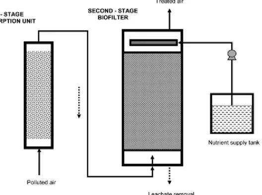
(30) About 25 to 35% of low concentrations of benzene, toluene and chlorobenzene were removed, while other chlorinated VOCs could not be removed in the biotrickling filter. The low VOC removal was attributed to the presence of inhibitory concentrations of sulphate in the recycle liquid and the possible accumulation of metabolites other than sulphate that inhibit VOC biodegradation. Emissions from pulp and paper industries contain hydrogen sulphide, methanol and α-pinene, representative inorganic, hydrophilic, and hydrophobic organic pollutants.[ 81 ] A two-stage biological system (Figure 10) comprising a first-stage biofilter and a second-stage biotrickling filter was proposed to treat this complex gas-phase pollutant mixture. In that study, the biotrickling filter was inoculated with autotrophic hydrogen sulphide degraders and an acid-tolerant yeast (Candida boidinii), while the biofilter was inoculated with the fungus Ophiostoma stenoceras, and experiments were performed at different inlet loading rates and process conditions. Hydrogen sulphide and methanol were removed in the first-stage biotrickling filter with maximum elimination capacities of 45 and 894 g/m3.h, while α-pinene was removed predominantly in the second-stage fungal biofilter with a maximum elimination capacity of 138 g/m3.h. The original idea was initially to remove H2S in the first reactor, with medium acidification, and all the VOCs in the second reactor at constant pH. However, the acidipholic methanol degrader inoculated in the first reactor appeared to be highly acid-tolerant, and methanol was easily removed in the first-stage together with H2S. Chitwood and Devinny[ 82 ] evaluated the feasibility of using a two-stage biofilter for the treatment of H2S, air toxics and smog precursors. The first-stage acid-gas biofilter packed with lava rock contained acidophilic autotrophic bacteria to remove H2S, while the second-stage wood chip biofilter removed other air toxics that included methanol, acetone, methylene chloride, chloroform, toluene, xylene, ethylbenzene, methyl-tertbutyl-ether (MTBE) and 2-methyl butane. However, they observed that the first-stage AGB removed acetone and methanol completely, while other VOCs were intermittently removed depending on the concentrations, in addition to 99.6% removal of H2S at an inlet loading rate of 0.057 g/m3.h. Conclusions The mechanism of pollutant removal in the most commonly used biological and nonbiological waste-gas treatment systems, and the advantages of combining biological systems with physico/chemical systems were reviewed in this paper. An adsorption unit, when used as a pre-treatment step for a bioreactor, would handle dynamically varying pollutant loads acting as a buffering unit during shock-loads and as a feeding source to the bioreactor during starvation periods. However, adsorption units can also be used as “polishing” units, when placed as a second-stage treatment process after a bioreactor. Another well known combination consists in using a scrubber as a pre-.
(31) treatment step followed by a bioreactor. Such a combination, known as a bioscrubber, is above all suitable for relatively highly water-soluble pollutants. Photooxidation of volatile pollutants offers many advantages, both as a stand-alone system and when combined with a bioreactor for waste-gas treatment. Our own experience suggests, however, that the efficiency of using UV only (photolysis) is rather limited compared to a UV-TiO2 system (photocatalysis). Under well-optimized conditions, photocatalytic reactors can effectively withstand short-term shock-loads and reduce pollutant loads to levels acceptable in a biological system, showing the potential suitability of this technique as a pre-treatment step. Additionally, the water-soluble end-products from the photoreactor can afterwards effectively be removed in the second-stage bioreactor without hindering the activity of the microorganisms. However, depending on the nature and composition of the wastegas, and the degree of treatment attained in the bioreactor, a photocatalytic reactor can be designed/modified to be used a pre- or post-treatment step. The combination of two bioreactors in series can be recommended in the following situations: (i) when the waste-gas contains a mixture of inorganic and organic pollutants; and some of their degradation end-products are highly acidic, the first-stage bioreactor can host a mixture of acid-tolerant microorganisms in order to eliminate those pollutants, and (ii) when two different groups of pollutants need to be degraded, different microbial species can be maintained in each bioreactor that are specific for the given pollutants. In the latter situation, i.e., for waste-gas containing a mixture of hydrophilic and hydrophobic compounds, the hydrophilic pollutants can be treated in one bioreactor while the hydrophobic substrates can be treated in the bioreactor with addition of an organic phase such as silicone oil if needed..
(32) Nomenclature AOC. Assimilable organic compound. AOPs. Advanced oxidation processes. BET. Branauer-Emett-Teller. BOD. Biological oxygen demand. BF. Biofilter. BTEX. Benzene, toluene, ethylbenzene and xylene. BTF. Biotrickling filter. COD. Chemical oxygen demand. CPR. Carbon dioxide production rate. CSTB. Continuous stirred tank bioreactor. DCM. Dichloromethane. DOC. Dissolved organic carbon. EBRT. Empty bed residence time. EC. Elimination capacity. EC50. Half maximal effective concentration. GAC. Granular activated carbon. L/G. Liquid to gas ratio. L-H. Langmuir-Henshelwood. MB. Monolith bioreactor. MEK. Methyl-ethyl-ketone. MIBK. Methyl-isobutyl-ketone. MLR. Mass loading rate. MTBE. Methyl-tert-butyl-ether. PCE. Perchloroethylene. PCO. Photocatalytic oxidation. PSA. Pressure swing adsorption. RE. Removal efficiency. TCE. Trichloroethylene. TOC. Total organic carbon. TSA. Temperature swing adsorption. UF. Unit flow. UV. Ultraviolet. VICs. Volatile inorganic compounds. VOCs. Volatile organic compounds. b. Equilibrium constant. Ce. Equilibrium concentration of the pollutant (g/m ). 3. 3. Cin , Cout. Inlet and outlet pollutant concentrations (g/m ). Cln. Logarithmic mean concentration of the VOC at the inlet and the outlet of the bioreactor (g/m ). 3. 3. CO2,in, CO2,out Inlet and outlet CO2 concentrations of the bioreactor (g/m ) 3. Csv −. Concentration of the pollutant saturated vapour (g/m ) +. e /h. Electron-hole pairs. K. Adsorption equilibrium constant in L-H kinetics (m /mol). 3.
(33) K. Empirical constant. k. L-H reaction rate constant (mol/m .min). Ks. Half-saturation constant (g/m ). 3. 3. N OH. Empirical constant −. Hydroxide ion. OH*. Hydroxyl radical. ppmv. Parts per million (volume basis). Q. Gas flow rate (m /h). qm. Maximum adsorption capacity (g/kg). qmono. Maximum adsorption capacity of the first adsorbed layer (g/kg). R. VOC removal rate (g/m .h). V. Volume of the reactor or packed bed or aqueous medium (m ). 3. 3. 3. 3. Vm. Maximum pollutant removal rate (g/m .h). α. Constant of BET model. Acknowledgments The authors would like to acknowledge the financial support of the Spanish Ministry of Foreign Affairs (project A/024301/09), and European FEDER funds. ERR is also grateful to the Spanish Ministry of Science and Innovation for his research contract (JCI-20083109). References • •. •. •. •. •. • •. 1. Khan, F. I. and Ghoshal, A. K. 2000. Removal of volatile organic compounds from polluted air. J. Loss Prev. Proc. Ind., 13: 527–545. 2. Ottengraf, S. P.P. 1986. “Exhaust gas purification”. In Biotechnology, Edited by: Rehm, H. J. and Reed, G. Vol. 8, 425–452. Weinheim, Germany: VCH Verlagsgesellschaft. Chapter 12 3. Kennes, C. and Veiga, M. C. 2001. “Conventional biofilters”. In Bioreactors for Waste Gas Treatment, Edited by: Kennes, C. and Veiga, M. C. 47–98. Dordrecht: Kluwer Academic Publisher. 4. Heymes, F., Manno-Demoustier, P., Charbit, F., Fanlo, J. L. and Moulin, P. 2006. A new efficient absorption liquid to treat exhaust air loaded with toluene. Chem. Eng. J., 115: 225–231. 5. Kennes, C., Montes, M., López, M. E. and Veiga, M. C. 2009. Waste gas treatment in bioreactors: Environmental engineering aspects. Can. J. Civ. Eng., 36: 1887–1894. 6. Rene, E. R., Arulneyam, D. and Swaminathan, T. 2004. “Biofiltration”. In Concise Encyclopedia of Bioresource Technology, Edited by: Pandey, A. 31–39. New York, NY: Haworth Press. 7. Kennes, C., Rene, E. R. and Veiga, M. C. 2009. Bioprocesses for air pollution control. J. Chem. Technol. Biotechnol., 84: 1419–1436. 8. Higbie, R. 1935. The rate of absorption of pure gas into a still liquid during short periods of exposure. Trans. AIChE L1, : 365–389..
(34) • •. •. • • •. •. •. • •. •. •. • •. •. •. 9. Schnelle, K. B. and Brown, C. A. 2002. “Absorption for HAP and VOC Control”. In Air Pollution Control Technology Handbook, Boca Raton, Florida: CRC Press. 10. de Hullu, J., Maassen, J. I.W., van Meel, P A., Shazad, S. and Vaessen, J. M.P. 2008. Comparing different biogas upgrading techniques, The Netherlands: Eindhoven University of Technology. 11. Kapdi, S. S., Vijay, V. K., Rajesh, S. K. and Prasad., R. 2005. Biogas scrubbing, compression and storage: perspective and prospectus in Indian context. Renew. Energy, 30: 1195–1202. 12. Schlegelmilch, M., Streese, J. and Stegmann., R. 2005. Odour management and treatment technologies: An overview. Waste Manage., 25: 928–939. 13. Ruthven, D. M. 1984. Principles of adsorption processes, New York: John Wiley. 14. Hamdi, B. M., Houari, S. A., Hamoudi, Z. Ait. and Kessaïssia, Z. 2004. Adsorption of some volatile organic compounds on geomaterials. Desalination, 166: 449–455. 15. Bagreev, A., Menendez, J. A., Dukhno, I., Tarasenko, Y. and Bandosz, T. J. 2005. Oxidative adsorption of methyl mercaptan on nitrogen-enriched bituminous coal-based activated carbon. Carbon, 43: 208–210. 16. Pichat, P. 2003. “Photocatalytic Degradation of Pollutants in Water and Air: Basic Concepts and Applications”. In Chemical Degradation Methods for Wastes and Pollutants, Edited by: Tarr, M. A. New York: Marcel Dekker Inc. 17. Lichtin, N. N. and Sadeghi, M. 1998. Oxidative photocatalytic degradation of benzene vapor over TiO2. J. Photochem. Photobiol. A: Chem., 113: 81–88. 18. Jeong, J., Sekiguchi, K. and Sakamoto, K. 2004. Photochemical and photocatalytic degradation of gaseous toluene using short-wavelength UV irradiation with TiO2 catalyst: comparison of three UV sources. Chemosphere, 57: 663–671. 19. Xie, C., Xu, Z., Yang, Q., Li, N., Zhao, D., Wang, D. and Du, Y. 2004. Comparative studies of heterogeneous photocatalytic oxidation of heptane and toluene on pure titania, titania-silica mixed oxides and sulfated titania. J. Mol. Cat. A: Chem., 217: 193–201. 20. Palau, J., Penya-Roja, J. M., Gabaldón, C., Álvarez-Hornos, F. J., Sempere, F. and Martínez-Soria, V. 2011. UV photocatalytic oxidation of paint solvent compounds in air using an annular TiO2-supported reactor. J. Chem. Technol. Biotechnol., 86: 273–281. 21. Shen, Y. S. and Ku, Y. 2002. Decomposition of gas-phase trichloroethene by the UV/TiO2 process in the presence of ozone. Chemosphere, 46: 101–107. 22. Pengyi, Z., Fuyan, L., Gang, Y., Qing, C. and Wanpeng, Z. 2003. A comparative study on decomposition of gaseous toluene by O3/UV, TiO2/UV and O3/TiO2/UV. J. Photochem. Photobiol. A: Chemistry, 156: 189–194. 23. Hager, S., Bauer, R. and Kudielka, G. 2000. Photocatalytic oxidation of gaseous chlorinated organics over titanium dioxide. Chemosphere, 41: 1219– 1225. 24. Rezaee, A., Pourtaghi, Gh. H., Khavanin, A., Mamoory, R. S., Ghaneian, M. T. and Godini, H. 2008. Photocatalytic decomposition of gaseous toluene by TiO2 nanoparticles coated on activated carbon. Iran J. Environ. Health Sci. Eng., 5: 305–310..
(35) •. •. •. •. •. •. •. •. • • •. •. • •. •. 25. Hoffmann, M. R., Martin, S. T., Choi, W. and Bahnemann, D. W. 1995. Environmental applications of semiconductor photocatalysis. Chem. Rev., 95: 69–96. 26. Kim, S. B. and Hong, S. C. 2002. Kinetic study for photocatalytic degradation of volatile organic compounds in air using thin film TiO2 photocatalyst. Appl. Catal. B: Environ., 35: 305–331. 27. Driessen, M. D., Miller, T. M. and Grassian, V. H. 1998. Photocatalytic oxidation of trichloroethylene on ZnO: characterization of surface-bound and gas-phase products and intermediates with FT-IR spectroscopy. J. Mol. Catal. A: Chem., 131: 149–156. 28. Mohseni, M. 2005. Gas phase trichloroethylene (TCE) photooxidation and byproduct formation: photolysis vs. titania/silica based photocatalysis. Chemosphere, 59: 335–342. 29. Hung, W.-C., Fu, S.-H., Tseng, J.-J., Chu, H. and Ko, T.-H. 2007. Study on photocatalytic degradation of gaseous dichloromethane using pure and iron ion-doped TiO2 prepared by the sol-gel method. Chemosphere, 66: 2142–2151. 30. Fan, J. and Yates, J. T. 1996. Mechanism of photooxidation of trichloroethylene on TiO2: detection of intermediates by infrared spectroscopy. J. Am. Chem. Soc., 118: 4686–4693. 31. Haag, W. R., Johnson, M. D. and Scofield, R. 1996. Direct photolysis trichloroethylene in air: effect of contaminants, toxicity of products, and hydrothermal treatment of products. Environ. Sci. Technol., 30: 414–421. 32. Augugliaro, V., Coluccia, S., Loddo, V., Marchese, L., Martra, G., Palmisano, L. and Schiavello, M. 1999. Photocatalytic oxidation of gaseous toluene on anatase TiO2 catalyst: mechanistic aspects and FT-IR investigation. Appl. Catal. B: Environmental, 20: 15–27. 33. Al Momani, F. 2007. Treatment of air containing volatile organic carbon: elimination and post treatment. Environ. Eng. Sci., 24: 1038–1047. 34. Al Momani, F. and Jarrah, N. 2009. Solar/UV-induced photocatalytic degradation of volatile toluene. Environ Technol., 30: 1085–1093. 35. Chen, J. M., Cheng, Z. W., Jiang, Y. F. and Zhang, L. L. 2010. Direct VUV photodegradation of gaseous α-pinene in a spiral quartz reactor: intermediates, mechanism, and toxicity/biodegradability assessment. Chemosphere, 81: 1053– 1060. 36. Kitis, M. M., Adams, C. D. and Daigger, G. T. 1999. The effects of Fenton's reagent pretreatment on the biodegradability of non-ionic surfactants. Water Res., 33: 2561–2568. 37. Baltrenas, P. and Zagorskis, A. 2009. Investigation of cleaning efficiency of a biofilter with an aeration chamber. J. Environ. Landscape Manage., 17: 12–19. 38. Waweru, M., Herrygers, V., Langenhove, H. V. and Verstraete, W. 2005. “Process Engineering of biological waste gas purification”. In Environmental Biotechnology: Concepts and Applications, Edited by: Jördening, H.-J. and Winter, J. 409–425. Asia: John Wiley and Sons. 39. Rene, E. R., López, M. E., Veiga, M. C. and Kennes, C. 2010. Performance of a fungal monolith bioreactor for the removal of styrene from polluted air. Bioresour. Technol., 101: 2608–2615..
Figure


+7


Documento similar
El alumno podrá entender y compartir información acerca de experiencias, eventos pasados que continúan en el presente, hablar acerca de sentimientos personales
For a subdomain of the domain of classical marriage markets for which matching agents of the same gender is not feasible, Sasaki and Toda (1992) characterized the core by
Being governance a proposed guide for transforming the binomial State-society (Bevir & Rhodes, 2006) or the trinomial composed by the state, civil society and the private
Electronic waste (e-waste), have a high potential as a source of precious metals, since they can contain metals like silver, gold, platinum, copper, zinc, nickel, tin and
DCAT application profile for data portals in Europe (DCAT-AP) is a specification for describing catalogs and datasets from public sector data portals, using metadata, in a way
While PETE students of the control group followed a traditional educational approach based on attending master-classes, practical sessions, and the successful completion of
Chan and Golay (1977) developed a numerical technique to design a drift eliminator for a particular cooling tower by setting a pressure drop limit and then choosing the geometry
The proposed safety requirements elicitation process is based on a mix of different techniques and standards, as no single standard or technique address all the different,
