A common platform approach to the development of training simulators with real time dynamics
81
0
0
Texto completo
(2) PONTIFICIA UNIVERSIDAD CATOLICA DE CHILE ESCUELA DE INGENIERIA. A COMMON-PLATFORM APPROACH TO THE DEVELOPMENT OF TRAINING SIMULATORS WITH REAL-TIME DYNAMICS. CRISTIÁN EDUARDO GÓMEZ BARRIOS. Members of the Committee: LUCIANO E. CHIANG DIEGO CELENTANO SERGIO QUIJADA ERNESTO CRUZ. Thesis submitted to the Office of Research and Graduate Studies in partial fulfillment of the requirements for the Degree of Master of Science in Engineering Santiago de Chile, January, 2009.
(3) Gratefully to my family. ii.
(4) ACKNOWLEDGEMENTS. The authors would like to thank the FONDEF program of CONICYT- CHILE for partially funding this research through projects TE06I1004 and TE08I1005, and to División Andina of Codelco-Chile for information and technical support given.. iii.
(5) TABLE OF CONTENTS. ACKNOWLEDGEMENTS ........................................................................................ iii LIST OF FIGURES..................................................................................................... vi LIST OF TABLES ..................................................................................................... vii ABSTRACT .............................................................................................................. viii RESUMEN .................................................................................................................. ix 1.. INTRODUCTION .............................................................................................. 1 1.1. Training simulators advantages in learning ................................................. 1 1.2. Relevant previous experiences..................................................................... 3 1.3 Our proposal ................................................................................................. 5. 2.. AN ARCHITECTURE FOR DEVELOPING TRAINING SIMULATORS ..... 7 2.1. Kinematics equations ................................................................................. 10 2.1.1. Positions and orientations............................................................... 10 2.1.2. Linear and angular velocities ......................................................... 11 2.1.3. Linear and angular accelerations .................................................... 11 2.2. Dynamics equations ................................................................................... 12 2.2.1. Dynamic forces .............................................................................. 12 2.2.2. Dynamic moments of force ............................................................ 12 2.2.3. Unknown variables ......................................................................... 13 2.3. Graphics ..................................................................................................... 13. 3.. TRAINING SIMULATOR FOR A MANIPULATOR USED IN THE COPPER MINING INDUSTRY ...................................................................................... 16 3.1. Approach of the copper mining Industry ................................................. 16 3.1.1. SAG Mill........................................................................................ 17 3.1.2. Identification of wasting and propose saving ................................ 21 3.1.3. Operator of the Manipulator of liners ............................................ 22 3.1.4. Manipulator of liners ..................................................................... 25 3.1.5. Main characteristic for the Manipulator of liners .......................... 26 iv.
(6) 3.1.6. Cost for the maintenance of the manipulator of liners................... 26 3.2. Methodology to develop a training simulator .......................................... 30 3.2.1. Goals for the simulator .................................................................. 30 3.2.2. Console implementation ................................................................ 31 3.2.3. Simulation model ........................................................................... 37 3.2.4. Model of the liner .......................................................................... 42 3.2.5. Training procedure ......................................................................... 44 3.2.6. Learning by game playing ............................................................. 45 3.2.7. Examples of the training procedure as a video game .................... 47 4.. RESULTS AND PROPOSE FUTURE WORK ............................................... 51. 5.. CONCLUSIONS .............................................................................................. 52. REFERENCES ........................................................................................................... 53 APPENDIX ................................................................................................................ 57 APPENDIX A. MANIPULATOR INPUT MODEL ................................................. 58 APPENDIX B. WORKING ENVIRONMENT IN SAG MILL MAINTENANCE . 60 APPENDIX C. PROCEDIMIENTO DE OPERACIÓN DE LA MANTENCIÓN ... 66 •. Trabajos de Preparación (componentes a utilizar) ......................... 66. •. Desenergización y Bloqueos de los Equipos ................................. 66. •. Desmontaje y Extracción del Chute de Alimentación ................... 66. •. Traslado e Instalación de la Lainera .............................................. 66. •. Desmontaje de Corazas Gastadas .................................................. 67. •. Ingreso de Elementos de Desgaste Nuevos ................................... 68. •. Montaje de Corazas Nuevas (cilindro y tapas) .............................. 69. •. Montaje de Elementos de Desgaste Cónicos (Descarga) ............... 70. •. Giro del Molino ............................................................................. 70. v.
(7) LIST OF FIGURES 2.1 Model specification commands. .................................................................................................... 7 2.2 Flow Diagram for a Simulation Loop in PADROB. ..................................................................... 9 2.3 Basic models showing the connections of two bodies. Prismatic joint (left). Revolute joint (right). ............................................................................................................................................ 14 2.4 Structure of the simulator environment. ...................................................................................... 15 3.1 Flow diagram of Andina. ............................................................................................................. 17 3.2 Outside of the SAG MILL (Left). Inside of the SAG MILL (Right). Close up showing liners mounted on the walls (below). ...................................................................................................... 18 3.3 New Liners (above). Liners with wear (below). ......................................................................... 19 3.4 Real Liner Manipulator. .............................................................................................................. 20 3.5 Manipulator placing a liner.......................................................................................................... 20 3.6 Operator at the command of the manipulator of liners. ............................................................... 23 3.7 Operator working with the manipulator of liners. ....................................................................... 24 3.8 Proportional Valves for controlling the manipulator of liners. ................................................... 25 3.9 Arm structure with the minimal extension. ................................................................................. 27 3.10 Arm structure with the maximum extension. ............................................................................ 28 3.11 Manipulator operated with a wired control. .............................................................................. 29 3.12 Real and Mockup Manifold for the manipulator (above). Conventional joystick control (below). .......................................................................................................................................... 32 3.13 Construction plan of the proportional valve of control (sauer-danfoss). ................................... 33 3.14 Real control vs Made control..................................................................................................... 34 3.15 Spool. ......................................................................................................................................... 35 3.16 Control Platform of the simulator. ............................................................................................. 36 3.17 Converter of lineal movement into rotational movement .......................................................... 37 3.18 Generic display mode (left). True geometry display mode (right). ........................................... 38 3.19 Model of the manipulator of liners. ........................................................................................... 38 3.20 Model of the manipulator of liners “dress”. .............................................................................. 39 3.21 Model and real manipulator. ...................................................................................................... 40 3.22 Manipulator motions.................................................................................................................. 40 3.23 Model of the kinematic chain of the liner.................................................................................. 42 3.24 Model of the kinematic chain of the manipulator and the liner. ................................................ 43 3.25 Model of the kinematic chain of the manipulator and the liner “dressed”. ............................... 43 3.26 Structure of the proposed learning strategy. .............................................................................. 46 3.27 Tutorial 0 tasks .......................................................................................................................... 47 3.28 Tutorial 3 tasks .......................................................................................................................... 48 3.29 Tutorial 5 tasks .......................................................................................................................... 49 3.30 Tutorial 7. Full scale simulation. .............................................................................................. 50. vi.
(8) LIST OF TABLES. 3.1 Simulator’s economic justifications ............................................................................................ 22. vii.
(9) ABSTRACT. In this work the theoretical and practical aspects of a methodology for developing training simulators are discussed and applied to the development of a simulator training and tutoring system used in the copper mineral processing industry. Recent research has demonstrated a positive effect on learning by using tutoring systems within virtual worlds and video games as teaching aids, but the development of a new training simulator or the modification of an existing one generally requires a considerable amount of effort, both time and cost wise. Our approach is to reduce the effort required to develop training simulators for operating mechanical equipment based on the development of a reusable core software package called PADROB that solves the real time kinematics, dynamics and 3D graphics display of mechanisms. In this software the equations of motion of a mechanism are automatically generated from a connectivity model (offline) and then solved numerically in real time during simulator operation. User input is done through a joystick or custom mock-up console, and the system responds according to the physical model. The package includes 3D graphics for showing a high fidelity model in motion. For illustrating the proposed methodology, a training simulator for the operation of a complex type of manipulator used inside of SAG Mills in the mineral processing industry is shown.. Keywords: Real-time dynamic simulator, distributed training simulator, manipulator of liners simulator, vocational training.. viii.
(10) RESUMEN. En este trabajo se discuten aspectos teóricos y prácticos de una metodología para el desarrollo de simuladores de entrenamiento y sus aplicaciones para el desarrollo de un simulador hecho a la medida, con un sistema de tutoriales para la enseñanza. Investigaciones recientes han demostrado un positivo efecto en el aprendizaje usando tutoriales en un mundo virtual, con video juegos como asistencia a la enseñanza, pero el desarrollo de nuevos simuladores de entrenamiento o la modificación de uno ya existente generalmente requiere un considerable esfuerzo, tanto de tiempo como de dinero. Nuestra propuesta es reducir el esfuerzo que se requiere en desarrollar un simulador de entrenamiento ocupando un equipo mecánico basado en el desarrollo de un software reusable llamado PADROB, que resuelve la cinemática y dinámica en tiempo real, desplegando en 3D los mecanismos. En el software las ecuaciones de movimiento del mecanismo son automáticamente generadas de un modelo conectado (offline) y luego las resuelve numéricamente en tiempo real durante la operación de simulación. La interacción del usuario se hace a través de un joystick o una consola construida a la medida. Incluye gráficos 3D que permite visualizar con una alta fidelidad el modelo en movimiento. La aplicación para ilustrar la metodología propuesta es un simulador para el entrenamiento en la operación de un complejo tipo de manipulador usado al interior del molino SAG, en la industria minera.. Palabras Claves: Simulador dinámico en tiempo real, distribuible simulador para entrenamiento, simulador de un manipulador de lianas, entrenamiento técnico.. ix.
(11) 1. INTRODUCTION. In this introductory section we will discuss general aspects of simulators when used as teaching or training aids as well as relevant previous experiences.. 1.1. Training simulators advantages in learning. Since live action exercises in any field are generally costly in terms of time, human resources, and material expenditures, recent advances in interactive digital technology provide an economical training alternative. Furthermore it has been established that the use of computer technology enhances learning, and that it can be effectively used alongside traditional methods such as classroom instruction and experiential learning (Raybourn, 2007; Chang et al, 2008). The capacity of personal computers and associated software technologies has improved to such a degree that it is now possible to develop relatively low cost simulators with high end capabilities (Hogue et al, 1999). Hence the use of computer based training methods has become a common practice. The motivations for using simulators are widely established, such as their potential for low cost training, new technology development, energy savings and research (Craighead et al, 2007), but above all, training can be carried out with a high degree of safety. This is of paramount importance when operators are in command of large and complex machines. Often, operators are required to work skillfully for many hours at a time; hence by using simulators they can be trained to keep up with the task without incurring into accidents (Stone, 2001). One of the main requirements in a simulator for skills development is that the training simulation must be performed in real-time. Training simulators are systems designed to emulate operational environments and process behaviors, with the purpose of skill development and experience acquisition of the operators.. The objective is to develop the necessary ability to. maximize the performance of the operator (Narayanasamy et al, 2006).. 1.
(12) It is important to emphasize the benefits of training with computer based simulators. Simulators can emulate the real world, giving the possibility to train the individual in the required activities for carrying out a real task (Herrington et al, 2007). To take full advantage of the simulator experience, a well known teaching strategy is the use of a simulator with a tutoring system based on game playing (Bowling et al, 2006; Annetta et al, 2008). The introduction of game playing features into simulators has been applied to improve learning, because ordering a clear task to the operator along with rewards and penalties, leads to more realistic risk management while training, which results in greater concentration on the task. Also incorporating rules into simulations enhances motivation, leading to greater attention and retention to training content (Garris et al., 2002; Sauvé et al., 2007). The overwhelming majority of research in game based tutoring systems has been focused on children, leaving the professional field largely untouched (Ebner and Holzinger, 2007; Craighead, 2008). Vocational learning is focused on real world tasks and using games for teaching can ease up the operator’s learning process (Hamalainen, 2008). According to Alexander et al. (2005) a video game based training system permits acquiring knowledge and skills efficiently while the user is playing. The acquisition of knowledge and skills by game playing is enhanced by physical fidelity, which is defined as the degree to which the physical simulation looks, sounds, and feels like the real operational environment. One last important benefit of computerized training systems worth to mention is that they give the user with more control over the amount of the training time, because of the increased equipment availability (Duffy et al., 2004).. 2.
(13) 1.2. Relevant previous experiences. In the past, the advanced technology used in simulators was restricted mostly for military purposes or to high profit industries such as aviation. In the past also, simulation technology was seldom real time (Narayanasamy et al., 2006). Nowadays, real time simulation is an essential feature for a proper training experience. Ideally for cost effective, efficient and quality development of training simulators a general purpose simulation environment would be necessary. However, according to Korkealaakso et al. (2007), standalone software capable of building a simulator consisting on real-time dynamics, 3D stereo visualization, and a motion platform is not yet available. Existing CAD commercial software to create graphics for a simulation model are not a good choice due the excessive details that they include, so the performance is very limited in these cases. Most of the existing real-time simulators for operator training are case-specific developed, such as in an air pilot or truck driver training simulators. The reason is because in seeking performance they are based on the specific mathematical equations of the simulated mechanical system. However this makes them costly for development, and difficult for upgrading. The core software is not of general purpose and hence not easily reusable or reconfigurable, as would be the case with a system that can automatically generate the equations of motion from a multibody system connectivity specification. Furthermore, most simulators do not use accurate physics models to generate motions; instead they usually use a simplified model, which makes reality under study most likely be distorted. Our research focuses on these two issues with the methodology described in the coming sections. In order to identify minimum features in an effective training simulator, we shall discuss the characteristics of some of the best known in the following paragraphs. -Grimsel et al. (2007) developed a driving simulator for tractors using open source software based on an existing driving simulator. It uses Linux as operating system and Stewart platform as a motion base. -Shiiba and Suda (2007) developed a driving simulator based on a simplified multibody analysis method. The multibody system consists in 13 rigid bodies; it uses Euler parameters for. 3.
(14) describing the direction of each body and Runge-Kutta method as the integration solver. In order to increase its calculation speed, the multibody analysis program was written in C language. -Cha et al. (2008) proposed a driving simulator that uses motion equations and a real-time computational model of the vehicle’s dynamics to create motions. The simulator synthesizes real motions from captured images in order to preserve natural and controllable motions. In regard to the dynamics modeling, they used simplifications with a trade-off between the simulation accuracy and the real-time performance. Thanks to real data recorded motions, it produces highly realistic motions that would be difficult to generate even with an accurate and sophisticated mathematical dynamics model. The above mentioned simulators have in common that they are case-specific developed since no common general purpose dynamics and graphics package is reported. On the other hand, there are software packages for developing simulators such as: -USARSim is a multiplatform and open source software, built upon Unreal Engine 2.0, a commercial game engine produced by Epic Games. It is nowadays a widely used robot simulator but it is argued that its physics engine does not have a really good throughput and requires an expert knowledge of the commands list to use it (Carpin et al., 2007; Craighead et al., 2007). -Microsoft Robotics Studio, software oriented to the development and simulation of real robots. It includes an effective visual programming tool, making it easy to develop and debug robot applications. It enables developers to generate modular services for hardware and software, allowing users to interact with robots through Web based or Windows-based interfaces. For the generation of models it has a moderate difficulty (Tick, 2006; Craighead et al, 2007; Tsai et al, 2008). -Korkealaakso et al. (2007) proposed a method to develop real time simulators, which uses the commercial software RT-LAB system made by Opal_RT as their real-time system. It also uses Matlab/Simulink to create the interfaces, OpenGL for graphics, and OpenAL for audio libraries. A gantry crane simulator is presented as an application of the methodology and the dynamics model used is from a previous work by Rouvinen et al. (2005), where the formulation implemented in the dynamics solver is based on Newton-Euler equations and on Lagrange Multipliers. A main drawback here is that the model must be created with yet other software, since their methodology and platform only considers importing the model with no functionality for creating one.. 4.
(15) -Unity, a commercial game engine and development environment, uses the Macintosh architecture as its base platform. It has a high physical fidelity and is easy to use. The professional version includes OpenGL. C++ plugins are created to add features to the engine, and the application can be compiled for a Windows platform. Unity requires a high end system to run optimally and the development environment is only available for Mac OS X (Craighead, 2008). It is important to mention that in the majority of cases the above solutions are oriented mainly towards video-game development.. 1.3 Our proposal Judging from the previous discussion, working and contributing towards a truly general dynamics and graphics package for developing physics-based simulators should be a contribution to the state of the art. In this work we propose a methodology to generate low cost but high quality simulators based on a general dynamics and graphics simulation package called PADROB. Using such a package allows generating a very wide variety of simulators just by changing the input connectivity model without having to derive the kinematical, dynamical and graphics display equations each time. An approach like this saves a lot of time in software development and testing. A general package has to perform more calculations during simulation than a case-specific simulator, but if the general package is efficient it is still capable of generating a high-quality realtime simulation even for rather high complexity models, as shown in the next sections. PADROB is a software developed specifically for educational purposes applied to mechanical system simulation, and from the start a great effort has been made to obtain a very flexible and easy modeling scheme. The commands are simple and intuitive and it has low system requirements. The package itself is standalone integrating the kinematics, dynamics solvers and graphics display in one. The proposed methodology is illustrated with a simulator for a special manipulator used for the replacement of liners in SAG mills. This simulator is used along with a training methodology based in game playing. The simulator has the porpoise of training the operator of the manipulator of liner, with the basic knowledge of the procedure of replacing liners at the maintenance of the SAG mill. 5.
(16) The model of the manipulator has all restriction as the actual machine, including its weights limitation, velocities, accelerations, etc. The training is going to be like a video game, so the operator enjoys the process of learning and makes this practice faster and effective. Now, the methodology of training is with tutorials for individual preparation of the operator (with respect to the use of the manipulator of liners). These tutorials will be used for the employees of the ELINTE (Elementos Industriales Tecnológicos) in a CD format, ready to use along with the simulator built in this thesis. The objective is the study of the efficiency of the simulator and tutorial proposed. ELINTE is an enterprise that gives service for the maintenance of SAG mill, they provided the specialized human resource for the replacement of liners (further information of this company is found in www.elinte.cl).. 6.
(17) 2. AN ARCHITECTURE FOR DEVELOPING TRAINING SIMULATORS The core is a software package called PADROB written by Chiang (2008) that automatically formulates the equations of motions starting from a model that specifies the bodies in the mechanical system, their inertial properties and the connectivity among them. It is written in C++ and uses the OpenGL 3D graphics library. At simulation run time, the kinematic and dynamic equations are solved algorithmically in real time and the resulting motion is displayed in the screen. The input of the model is done in a simple, flexible and efficient language. Figure 2.1 shows the model editing window. PADROB automatically parses, recognizes and subdivides the input model into kinematics chains. Joints are automatically classified in degrees of freedoms or dependents degrees (Oyarzún, 2007).. FIGURE 2.1. Model specification commands.. PADROB can solve the kinematics problems of position, velocities and acceleration of any point in the mechanism. For this purpose it uses an iterative approach based on Chasle’s law (see 7.
(18) next section for a more detailed explanation). It uses the Newton-Euler formulation to obtain the equations of motion for simulating the behavior of a mechanism over a period of time, while subject to a set of external forces. The Newton-Euler equations are subsequently transformed to an equivalent set of state space equations. This allows use Runge-Kutta integration scheme to solve for: velocities and accelerations of the bodies’ center of gravity, bodies’ angular velocities and accelerations, as well as moments and force reactions at each joint. Figure 2.2 shows a flow diagram of the dynamics simulation engine in PADROB.. 8.
(19) FIGURE 2.2. Flow Diagram for a Simulation Loop in PADROB.. 9.
(20) An advantage of using a dynamic multibody model is that can take into account the system inertia so the motion obtained by simulation is a realistic one. A large number of simulators use simplified models that do not take into account the inertia effects. Another very desirable advantage is that the parameters of the actual machine correspond one to one with the parameters of a multibody machine model (Shiiba et al, 2007). The advantage of using a general purpose dynamics simulation engine such as PADROB is that the same core software can be used for a different simulator just by changing the input model. The input model in PADROB only requires specification of the mechanism connectivity, the inertial properties of bodies and the set of external forces, so a new simulator can be made available in a fraction of the time required to build a new simulator from scratch.. 2.1. Kinematics equations The kinematic equations in PADROB are solved in an algorithmic way as explained next.. 2.1.1. Positions and orientations r r The position of any point P can be determined as 0 rP = 0 rP (q ) , where q = (q1,..., qi,...qn) is the set of generalized coordinates of a mechanism. Then the position of any point B in a body i can be determined as: r r 0r rB = 0 rA + 0 Ri i rAB. (2.1). Where 0 Ri is the rotation matrix of body i with respect to GRG (global reference frame) and i. r rAB is the relative distance between points A and B in body i local coordinates.. Therefore if all bodies are connected forming serial kinematic chains (open or closed) and at least one body is connected to ground, then any point (particularly the CG and joint reference positions) can be computed using iteratively (2.1), considering that there will be at least one joint connected to ground in all models. Because the kinematics and dynamics of the mechanisms are solved along serial kinematic chains, the solution is arrived much faster.. 10.
(21) 2.1.2. Linear and angular velocities By Chasle’s Law r r r r v P = v A + ω B × r AP (2.2) r r Where v P is the velocity of any point P in a body B to be computed, v A is the known velocity of a. r point A in body B, and ω B is the angular velocity of body B. For a prismatic joint we must add to (2.2) a relative velocity term given by r v jrel = q& j eˆ jr. (2.3). r Where, v jrel is the relative velocity at joint j (prismatic), q&j is the linear rate at prismatic joint j. and ê jr is the direction of prismatic joint displacement. For a revolute joint the angular velocity field is obtained by recursively applying the following equation: ω B 2 j = ω B1 j + q& j eˆ ja With ω B1 j as the angular velocity of body 1 connecting to joint j,. (2.4) ω B 2 j is the angular. velocity of body 2 connecting to joint j and ê ja is the axis of rotation of revolute joint j.. 2.1.3. Linear and angular accelerations The linear acceleration of a point P in the system can be obtained by applying recursively the expression below, r r r r r r r a p = a A + α B × rAP + ω B × (ω B × rAP ). (2.5). r r Where a A is the known acceleration of point A in body B and α B is the absolute angular acceleration of body B. For a prismatic joint we must add relative acceleration terms given by. 11.
(22) deˆ jr r a jrel = q&&j eˆ jr + 2q& j dt. (2.6). r Where, a jrel is the relative acceleration at joint j (prismatic), q&&j is the linear acceleration of. prismatic joint j and. deˆ jr dt. is the variation in time of the direction of the prismatic joint. displacement. For a revolute joint the angular acceleration field is obtained by recursively applying the following equation:. α B 2 j = α B1 j + q&& j eˆ ja + q& j. deˆ ja. (2.7). dt. Where α B1 j is the angular acceleration of body 1 connected to joint j, α B 2 j is the angular acceleration of body 2 connected to joint j and. deˆ ja dt. is the variation in time of the axis of rotation. of the revolute joint j.. 2.2. Dynamics equations. The 3D dynamics equations of motion by a state space approach. The acceleration field is obtained essentially through the Newton-Euler Equations.. 2.2.1. Dynamic forces v. ∑F =m. T. v ⋅ aG. (2.8). 2.2.2. Dynamic moments of force v. ∑M. G. ≈ v ≈ v v = ω × (I G ⋅ ω) + I G ⋅ α. (2.9). 12.
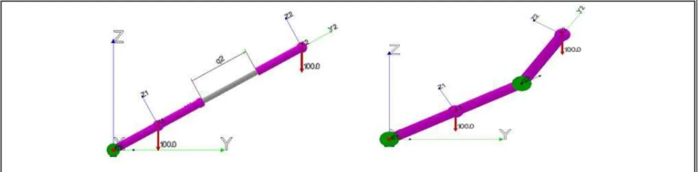
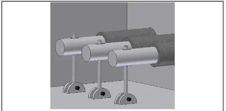
(23) 2.2.3. Unknown variables A system of equations is thus formed where the unknowns are: •. The absolute linear acceleration aGi of the center of mass G of each body i in the mechanism, i.e. three scalar unknowns per body.. •. The absolute angular acceleration α i of each body i, i.e. three scalar unknowns per body.. •. The reaction force at each joint, i.e. six scalar unknowns per joint, three per each connecting body: F j1 , F j 2. •. The reaction moment at each joint, i.e. six scalar unknowns per joint, three per each connecting body: M j1 , M j 2. •. The joint coordinate acceleration rate q&& j , one for each joint. Thus the vector of dynamic unknowns is the following:. .., aGix , aGiy , aGiz , α ix , α iy , α Giz ,... ..., F ja1 , F jr1 , F jt1 , F ja 2 , F jr 2 , F jt 2 , Xu = .M ja1 , M jr1 , M jt1 , M ja 2 , M jr 2 , M jt 2 ,... ...q j ... . (2.10). With i = 1,.., NB as the number of bodies and j = 1,.., NJ as the number of joints. Written in matrix form to solve the system above we can write: AX u = B. (2.11). The above system of equations it is a linear system and can be solved by any standard method, for example Gaussian Elimination.. 2.3. Graphics. The graphics engine is implemented for a Windows operating system. It is implemented using C++, and is based on the OpenGL library for the graphics environment. Figure 2.3 show in generic display mode, two types of connections used in PADROB. In generic/schematic display mode the bodies are drawn as purple bars. Revolute connections are drawn as green cylinders with the rotation axis in the longitudinal direction. Prismatic joints are 13.
(24) drawn as grey bars. Each body has a local reference frame and each joint has an ART (axisreference-tangential) coordinate system to define its reference directions in each body.. FIGURE 2.3. Basic models showing the connections of two bodies. Prismatic joint (left). Revolute joint (right). For high fidelity graphics the bodies in the model can be “dressed” with graphic primitive objects such as cylinders, spheres, general polygons and quadric surfaces that are attached to the bodies (Oyarzún, 2007). In order to cover the maximum surrounding display a three-screen set-up can be implemented, which allows the operator to have a higher feeling of immersion (Huang and Gau, 2003). In the figure 2.4, a schematic flow diagram of the operation of the simulator is shown.. 14.
(25) FIGURE 2.4. Structure of the simulator environment.. 15.
(26) 3. TRAINING SIMULATOR FOR A MANIPULATOR USED IN THE COPPER MINING INDUSTRY. An application of the proposed general approach for low cost development of Training Simulators is described in this section. This is a Training Simulator for operating a special type of manipulator in the copper mining industry when changing liners in a SAG mill. In the copper mining industry, the SAG mill is one of the most critical equipment in the entire process.. 3.1. Approach of the copper mining Industry The manipulator of liners studied works inside of the SAG mill of 36’-0’’ x 16’-9’’ and it belong to División Andina de Codelco Chile. It is shown in the flow diagram in fig. 3.1 that stopping the SAG mill would paralyze the entire line of production. For this reason, is of paramount importance that the mill stops the minimum time possible.. 16.
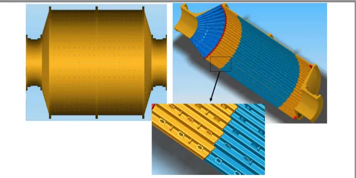
(27) III Panel Chancado Primario Norte. Chancado Primario Don Luis. Chancado Primario Sur. Mat. Fino Correa 4F. Chancado Secundario. Correa 5. Correa A6-A7. Tolvas de Grueso Tolva de Alimentación Molienda SAG. Chancado Terciario. Molienda SAG. Molienda Unitaria. Chancado Cuaternario. Molienda Convencional. Flotación Colectiva Flotación Selectiva. Concentrado de Molibdeno. Concentrado de Cobre. Tranque Los Leones. Embalse Ovejería. FIGURE 3.1. Flow diagram of Andina.. 3.1.1. SAG Mill The crushed mineral from previous stages enter inside the SAG mill through the transporter belt, which download the mineral, steel balls and reactive at the movil “chute” (the mineral is pass from the belt to the mill). Where they mixed and crushed inside the mill. The purpose of a SAG (Semi Autogenous) mill is to crush and reduce the incoming mineral to an adequate size for the following stages of the process. Ore size reduction is usually from 20 cm down to less than 0.18 mm. The SAG mill is a large size rotating cylinder, where mineral ore is revolved inside the mill and crushed by gravity. The interior walls of the SAG cylinder are tiled with liners which act to protect the main cylinder but most importantly to lift the ore so that a crushing effect is obtained by free fall impact. The steel liners or lifters initially weighing in the order of 4 500 kilograms will wear out after some time and must be replaced periodically.. 17.
(28) In fig. 3.2 a SAG mill schematics is shown with liners stacked along the inside walls. A closeup of the liners mounted on the interior walls is included in the same figure.. FIGURE 3.2. Outside of the SAG MILL (Left). Inside of the SAG MILL (Right). Close up showing liners mounted on the walls (below).. The process of replacing the liners is done with the help of a special manipulator, which is essentially a large size robotic arm with six degrees of freedom. This manipulator allows all the necessary motions for grasping the liners in order to remove the old ones and to mount the new ones. As shown in fig. 3.3, liners wear down steadily so after some time they must be replaced.. 18.
(29) FIGURE 3.3. New Liners (above). Liners with wear (below).. Safety is of paramount importance in liner replacement. Since the liner manipulator is a large mechanical arm, there is always the risk of colliding with other objects, or worse yet, hitting another worker within the work space. For this reason and the high energy consumption of the manipulator, it is used only during maintenance stops, which take in the order of 48 continuous hours. Fig. 3.4 and 3.5 shows the manipulator of liners operating inside the SAG mill.. 19.
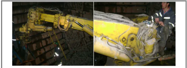
(30) FIGURE 3.4. Real Liner Manipulator.. FIGURE 3.5. Manipulator placing a liner.. 20.
(31) The maintenance downtime of the SAG mill must be kept to a minimum to avoid a sizeable loss of income, but the replacement of liners is a time-consuming task and for maximum productivity, the operator of the liner manipulator must have fully developed operational skills. The concentration plant has made several projects of improvement to increase the efficiency and reduce the maintenance time of the SAG mill. Such as the construction of a double arm manipulator of liners, liners restructure, platform and redesign for reduction of the number of pieces (less liners inside the SAG mill). The desired of continuous improvement in the process allow the incorporation of innovative methods and new technology, for these reason is that our proposal in this thesis takes real relevance, due is a present need.. 3.1.2. Identification of wasting and propose saving The cost for inefficiency in the SAG mill are around the US$80,000 and according to the data gathered by División Andina of Codelco (DAND), the SAG mill has an annual availability of 96.2%. Replacement of liners is a periodic task and it has to be done at least 3 times for year; each one of this maintenance takes nowadays around 85 hours. The rate of the increase the availability considers that for each hour additional of production, Division Andina earns benefits for USS$ 75,000. We propose that using the simulator the operator would have an increasing in his/her skill abilities, which will make them perform better and efficient movements reducing the time of operation. If with our proposal we manage to reduce the time of the operator in 15 minutes in each stop of the SAG mill, then the results of this improvement is shown in table 3.1.. 21.
(32) TABLE 3.1 Simulator’s economic justifications Replacement for year Time saving Increase of availability Cost for detention Gain for availability. h h / Year US$/h US$ / Year. 3 0.25 0.75 75,000 56,250. The table was made using data from the year 2007 and it shows that the saving for using the simulator would be of US$ 56,250, which would widely justify the utilization of the simulator. 3.1.3. Operator of the Manipulator of liners The simulator is focus on the training of the operators of the manipulator of liners, whom have the mission to replace the liners in the maintenance of the SAG mill. The operators of the manipulator are young technician (younger than 30 years old) with high psychomotor skill. In general, they don’t have university studies; instead, they went to technician’s high school for electricians and/or mechanics. Nowadays the selection process is through psychomotor test just like the one taken to obtain the driver’s license. Through the year, the operator works in different labors, where the task assigned is in direct relationship with his/her technician’s degree.. This is due there are only three maintenance every. year, is not justify have an operator only specialized for this task.. 22.
(33) FIGURE 3.6. Operator at the command of the manipulator of liners. The operator works sit (it is use a tractor’s sit), manipulating eight proportional valves as shown in fig. 3.7 and 3.8.. 23.
(34) FIGURE 3.7. Operator working with the manipulator of liners.. 24.
(35) FIGURE 3.8. Proportional Valves for controlling the manipulator of liners.. 3.1.4. Manipulator of liners For the year 2008, the manipulator of liners have been upgraded with the objective of reduce the time of maintenance. The cost of this upgrading developed for the Compañia Metalmecánica San Francisco LTDA (CMSF) was $ 175,080,244 (KUS$ 324). This value is only for the improvement of the machine and it is mention here just to have an idea of the real value for an equipment of similar characteristics. The value for the real machine differs due the demand, value of the components, size of the SAG mill, etc. There are more enterprises, mostly foreign, that build manipulators of liners, where varies a little in the geometry of the manipulator but all of them keeps the same concept (movements, degrees of freedom, etc).. 25.
(36) 3.1.5. Main characteristic for the Manipulator of liners Is an electro-hydraulic machine, capable of manipulate liners up to 4,500 kg., with double arm, independent system for each arm and with a back up unity for any deficiency that may occur. For the normal operation inside the mill, uses hydraulic cylinders with double effect. Its works using proportional electro valves with a local command. For its displacement uses hydraulics motorwheels activated for a proportional valve’s block, that allow its movements in both ways. To adapt to its final position it has proportional valve’s block which allow perform the turn of the central “tornamesa” It counts with back up accumulator in those critics lines of the machine, in particular focus in the “tomacorazas”. The control system used in the arms for the manipulator of liners, is made of a computer, a converter DC-DC in charge of provide the necessary voltage required for a 24 VDC, and a converter card. analog-digital that convert the analog signs from the joysticks and selectors into. digital signs. The total weight of the manipulator of liners is 30 tons.. 3.1.6. Cost for the maintenance of the manipulator of liners In average the expenses for the six years that the equipment has operate is an annual cost of US$ 43,760. With this data and considering the estimate saving of US$56,250 for the use of the proposed simulator, we could say that the maintenance of the manipulator of liners would be free of charge.. 26.
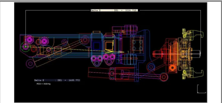
(37) 3.1.6.1. Plans of the manipulator of liners The manipulator of liners is an intellectual property of CMSF (compañia metalmecanica San Francisco), which made impossible to obtain the real plans of the machine. Instead the company provided with pictures of the main structures and their associated weights.. FIGURE 3.9. Arm structure with the minimal extension.. 27.
(38) FIGURE 3.10. Arm structure with the maximum extension. In a period of three months, the company (CMSF) was visited five times for the gathering of information of the manipulator of liners. In every visit the measurements of the mains structures were taken and it was collected the necessary information concerning the functioning of the machine. Finally a sketch of the manipulator was made and the inertia momentum were calculated for the main structures that formed part of the machine.. 28.
(39) FIGURE 3.11. Manipulator operated with a wired control.. 29.
(40) 3.2. Methodology to develop a training simulator The development of Training Simulators is described in this section.. 3.2.1. Goals for the simulator The goals set for developing the training simulator are the following:. Real-Time dynamics simulation: The simulated machine must move with the same response time than the real machine, so the trainee will acquire a true feeling for the speed of operation of the manipulator.. High fidelity graphics: The true and simulated machine and operating environment must look alike both geometrically, texture and color wise.. Low cost: An important cost in software development is usually programming man-hours. For quick and thus low cost development, a simulator development package such as PADROB is used. The generic package might run somewhat slower than a specifically customized dynamics equation solver but the development time is much less. The always increasing power of computer hardware allows to run the less efficient (in terms of speed of execution) but more flexible dynamics engine with the required time response for realistic training simulation.. High fidelity user I/O: For adequate skills development the user I/O must closely resemble the true operational interface. For this purpose the true hydraulic valve manifold of the manipulator will be used as input device in addition to joystick input. In this last case, the joystick mode is also helpful for teaching and rehearsing basic technical aspects of the manipulator. The simulator I/O interface is discussed next.. 30.
(41) 3.2.2. Console implementation When a real-time simulation is used for training purposes, the degree of immersion of the operator is vital for a successful learning experience, because a training exercise is only effective when the trainee feels the simulator as if it were the real machine. Then an acceptable simulator experience requires a physical simulation environment ad hoc to each simulated machine (Huang and Gau, 2003; Rouvinen et al, 2005). The physical control in our simulator can consist of either a USB game joystick controller, an industrial joystick or a replica of the real machine control. In the former case the core software uses a standard Windows API for reading the joystick input. Each joystick motion is associated to one actuator in the simulated machine. For a larger number of actuators than available joystick motions, the actuators are grouped into banks and the joystick is switched between banks using control buttons. In the latter case the replica uses encoders or potentiometers mounted in the rotation axis of the command bars of the mock-up hydraulic valves. The encoders and pot signals are fed into an analog to digital acquisition card which is read by the simulation software through input/output routines provided by the vendor. The same architecture for trainee input is used in all simulators, but the replica is replaced and customized for each specific case. Future research by the authors contemplates a generalized scheme to have physical feedback to the trainee through haptic devices such as a Stewart platform for the trainee seat. The focus of our research is not the development of specific simulators but instead to search for a general development approach applicable to any simulator, by having a flexible modeling scheme and a common dynamics simulation and graphics package. Fig. 3.12 shows that user controls can be a mock-up of the real valve controls and also a basic computer joystick.. 31.
(42) FIGURE 3.12. Real and Mockup Manifold for the manipulator (above). Conventional joystick control (below).. The controls will be made alike the real ones and it will be used the real building plans for the original controls (Sauer-Danfoss valves).. 32.
(43) FIGURE 3.13. Construction plan of the proportional valve of control (sauer-danfoss). The next figure (Fig. 3.14) shows the original controls in the manipulator of liners and the built ones for the simulator.. 33.
(44) FIGURE 3.14. Real control vs Made control.. It is important to emphasize that all have been built by the mechanics at the Pontificia Catolica University. As first control platform, it has been design a “box” in where only the valves will be seen as is shown in figure 3.14, which is what the operator sees in the real manipulator of liners. In the reality the move of the valves is convert from rotational to lineal. This spooler use this lineal shift to control the oil flow in the valves; the oil flow is what produce the move of the manipulator. Is for this reason that moves velocity can be regulated in the manipulator of liners (proportional move).. 34.
(45) FIGURE 3.15. Spool.. For the simulator, the inside of the box have been designed a system to convert the lineal move from the spool into a rotational move to adjust the analog potentiometer that allow produce the proportional move in the simulator, as the one produced in the real machine. The potentiometers are connected to the acquisition data card and finally the card is connected to the computer through the USB port. In fig. 3.16 and fig. 3.17 shows how the control box has been built.. 35.
(46) FIGURE 3.16. Control Platform of the simulator.. 36.
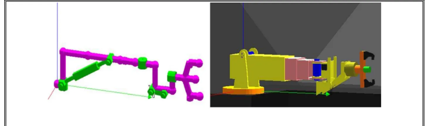
(47) FIGURE 3.17. Converter of lineal movement into rotational movement. 3.2.3. Simulation model The simulation model used for the liner manipulator is given in Appendix A. As mentioned before, there are no equations present, only the bodies in the system, their inertial properties, their connectivity, the external forces and the graphic primitives used for the rendering of the mechanism in motion. The equations of motion are automatically generated and solved in order to integrate the motion of the system while answering to the operator’s input. Figure 3.6 shows the graphical representation of the model, both in generic/schematic and true geometry display modes. The simulator of the dual manipulator is based on a multibody model consisting of 8 rigid bodies and 8 joints.. 37.
(48) FIGURE 3.18. Generic display mode (left). True geometry display mode (right).. With the sketch of the main bodies of the manipulator of liners (dimensions, weights, forms, geometry, moves, etc), the kinematic model was generated. Fig. 3.19 shows the final model of the manipulator of liners. Each number represents a body in the manipulator.. FIGURE 3.19. Model of the manipulator of liners. In Fig. 3.20 it is shown the same manipulator than before, but now it is “dressed up”. Each component from the manipulator corresponds to a letter.. 38.
(49) FIGURE 3.20. Model of the manipulator of liners “dress”. For each body (numbers) there is an inertial momentum associated, which was calculated using all the components (letters) that form part of the real manipulator. In the cases where there are more than one component for body, the inertial momentum associated it is taken for the closest body. The details for the inertia momentum calculus it is find at the appendix.. 39.
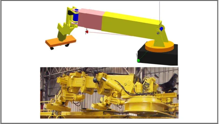
(50) FIGURE 3.21. Model and real manipulator.. The model has the same workspace and restrictions of the real manipulator and as it is shown in fig. 3.22 it has the same movements.. FIGURE 3.22. Manipulator motions.. 40.
(51) The model input format is extensively documented in the PADROB software manual (Oyarzún, 2007). Comments are preceded by double backslash characters. The first block of statements includes the list of bodies in the mechanism along with their inertial properties: masses, momentums of inertia and products of inertia. The moments of inertia and products of inertia are specified relative to a local reference system associated with each body. Each body statement starts with a letter B following the body ID number. The second block of statements lists the connections/joints between bodies. The statement for each joint starts with letter C followed by the joint ID number. A joint connects two bodies and it can be of three basic types: revolute, prismatic and pivoted with linear actuator. The proper combination of these three types allows modeling an enormous variety of mechanisms. The connection configuration is specified by giving the type, position, orientation with respect to each connected body. The joint connection can be powered by an electrical motor, hydraulic cylinder, pneumatic cylinder, servocontrol unit or not at all. In the case of the electric motor, for example, the Torque vs. angular velocity characteristics must be defined. A hydraulic cylinder is assumed to move with constant speed, which depends on the volume displacement of the hydraulic pump, and the nominal rpm of the electric motor of the power unit (usually a squirrel cage inductive motor). A pneumatic cylinder is assumed to provide a constant force, whose magnitude depends on the piston area and the air source working pressure. The servocontrol action requires specifying the PID (Proportional, Integrative and Derivative) gains for the feedback action. The next block of statements in the input model includes the external forces/torques acting over the system. Several types of forces/torque can be considered, for example of fixed, time varying or position dependant magnitude and/or direction. Special Forces generated by common practical elements such springs and dampers can also be included as well as drag and lift aerodynamic forces. Force statements start with letter F followed by the force ID number. Finally the last block of statements in the model file corresponds to graphic objects. Each graphic object statement starts with a G letter followed by the graphics object ID number. Each graphic object is associated with a given body in the system. Graphic objects are only used for rendering purposes, they are not considered in any way in the formulation nor the numerical integration of the equations of motion.. 41.
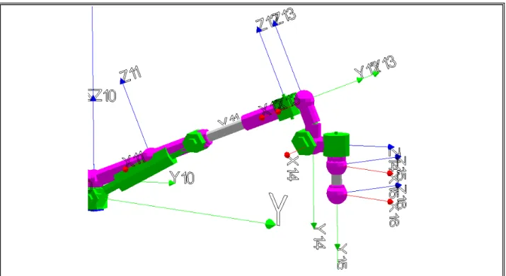
(52) 3.2.4. Model of the liner The way how the model of the liner built was using the same kinematic chain of the manipulator but simplified. For the inertial momentum calculus it was used the plan of the liners provided by División Andina. It is only at the extreme of the kinematic chain of the liner’s model (last body) where there is weight and inertial momentum, all the rest of the bodies in the kinematic chain have null weight and inertial momentum.. FIGURE 3.23. Model of the kinematic chain of the liner. In fig. 3.24 it is shown a comparison between the manipulator’s model and the liner’s model.. 42.
(53) FIGURE 3.24. Model of the kinematic chain of the manipulator and the liner.. FIGURE 3.25. Model of the kinematic chain of the manipulator and the liner “dressed”.. 43.
(54) 3.2.5. Training procedure For better and quicker skills development, it has been thought that the operator should complete a two part training program. The first part covers the theoretical concepts required at the operator level.. The second part uses the simulator intensively for actual operating skills. development. The objectives for the theoretical manual are: -Described completely the characteristics for the machine of study, indicating their technical data. -Give the algorithm and procedure of the rightful operation of the machine. -illustrate the working place, in particular where the maintenance is going to be done (SAG mill) and the procedure that it must be follow, along with the safety norms. -The next step is to watch a video that shows the manipulator and its working motions. This will provide the operator with the first idea of how the machine works and its function in liner replacement. The objectives for the operating manual are: -Using a video, the operator will acknowledge the movements that the manipulator can perform. -The operator will have to complete different tutorials, which will teach step by step the function of each component for the control of the manipulator of liners. -In this tutorials, the operator is going to be ask for develop simples task, which will be like if he/she would be playing a video game. Then, the operator would learn playing. All this has the purpose of have a motivated worker, who learn and develop his/her psychomotor skills.. 44.
(55) 3.2.6. Learning by game playing The second part of the training consists in actual practical training, and here the simulator is used intensively. This part of the training has been designed after a video game, where the operator must successfully complete different stages to be able to progress in his skill level. When the operator accomplishes a stage, a more difficult one follows where yet another set of restrictions are added such as (playing against time, evading obstacles, etc). At the beginning of each stage the operator watches a video of the task to accomplish next by using the simulator. In this way the operator has a better and faster understanding of the assignment (Taylor et al, 2008). Fig. 3.26 shows a schematics diagram of the intended learning process as discussed in the previous sections.. 45.
(56) FIGURE 3.26. Structure of the proposed learning strategy.. 46.
(57) 3.2.7. Examples of the training procedure as a video game In this section we will further illustrate the training method applied with the liner manipulator simulator. It is desired that the operator learns and dominates all the basic movements of the manipulator. Several tutorials are dedicated to this objective.. FIGURE 3.27. Tutorial 0 tasks. As shown in fig. 3.27 in the first tutorial the operator must reach the defined target using a model with only three degrees of freedom.. 47.
(58) FIGURE 3.28. Tutorial 3 tasks. In Tutorial 3 (fig. 3.28) the operator has to drive the manipulator towards a liner with a model with six degrees of freedom. In this part the user is not yet requested to grasp the liner, but he must leave the manipulator in the right position and orientation ready to grasp one. In Tutorial 5 the operator has the task to drive the manipulator to the liner, grasp it, and then position the liner as shown in fig. 3.29.. 48.
(59) FIGURE 3.29. Tutorial 5 tasks. In Tutorial 7, the operator must work in an environment inside the SAG mill as shown in fig. 3.30. He must carry out the real task, which is to grab a liner and place it at a given position inside a SAG mill. Practicing this maneuver successfully and repeatedly in the simulated environment will guarantee that when using the real manipulator, the maneuver will be executed safely and efficiently during maintenance stops.. 49.
(60) FIGURE 3.30. Tutorial 7. Full scale simulation.. 50.
(61) 4. RESULTS AND PROPOSE FUTURE WORK. For future work is proposed measure the efficiency of the simulator. To accomplish it, two focus groups would be select, one of them would have the same training procedure that nowadays are having and the second group would have the proposed methodology with the simulator and tutorials. This study will be applied by the workers from ELINTE, a leading company in the Chilean copper industry that specializes in SAG mills maintenance. Then, it will be measured statistics data for the performance of each one of the operator and it also will be collected the commentaries and opinions from the workers. After the measured the efficiency of the simulator is proved, the simulator could be used as an evaluator method for the selection of skills operator for the task asked.. 51.
(62) 5. CONCLUSIONS. The use of simulators as a medium for instruction provides many capabilities that cannot be duplicated within the traditional lecture format. It is been largely studied that using simulators is one of the best ways of training and learning. In this work we described a methodology to generate low cost simulators based on a general dynamics and graphics simulation package called PADROB. A flexible modeling scheme allows the simulator to be easily reconfigurable. Hence the development of a specific simulator is faster, and ultimately more economic. The tradeoff of this approach is that solving the dynamics equations and displaying graphics in a general way leads to less efficient software in terms of speed of execution. Fortunately, it is still possible to generate simulators with an adequate response time, even for a complex manipulator with 8 degrees of freedom as shown in the application example. The software is developed in the C++ language and uses OpenGL as the graphics library. It is freely available in www.rexlab.cl. User I/O interface can be configured for using a conventional joystick or a custom made clone control panel, interfaced through a Data Acquisition card. In the case of the application example, this methodology has allowed to develop an economical solution for a low volume but critical requirement in the training of operators of a type of manipulator for dexterously handling heavy objects (liners) inside SAG mills in the copper refining process. The implemented solution allows to train operators prior to maintenance stops, so when working against the clock, the level of skills is what is needed for maximum productivity.. 52.
(63) REFERENCES. Alexander, A.L., Bruny, T., Sidman, J. and Weil, S.A. (2005). From gaming to training: A review of studies on fidelity, immersion, presence, and buy-in and their effects on transfer in pc-based simulations. and. games.. Recover. from. http://www.darwars.com/downloads/DARWARS%20Paper%2012205.pdf. Annetta, L., Mangrum, J., Holmes, S., Collazo, K. and Cheng, M. (2008). Bridging realty to virtual reality: investigating gender effect and student engagement on learning through video game play in an elementary school classroom. International Journal of Science Education, 34, 1–23.. Bowling, M., Furnkranz, J., Graepel, T. and Musick, R. (2006). Machine learning and games. Machine Learning, 63, 211–215.. Carpin, S., Lewis, M., Wang, J., Balakirsky, S. and Scrapper, C. (2007). Usarsim: a robot simulator for research and education.. Proceedings of the International Conference on Robotics and. Automation (pp.1400–1405).. Cha, M., Yang, J. and Han, S. (2008). An interactive data-driven driving simulator using motion blending. Computers in Industry, 59 (5), 520-531.. Chang, K., Chen, Y., Lin, H. and Sung, Y. (2008). Effects of learning support in simulation-based physics learning. Computers & Education, 51, 1486–1498.. Chiang, L.E. (1995). Análisis Dinámico de Sistemas Mecánicos. Santiago, Chile: AlfaOmega.. Chiang, L., in press. Teaching robotics with a reconfigurable 3D multibody dynamics simulator. Computer Applications in Engineering Education.. 53.
(64) Craighead, J. (2008). Distributed, game-based, intelligent tutoring systems the next step in computer based training?. International Symposium on Collaborative Technologies and Systems (pp. 247-256).. Craighead, J., Murphy, R., Burke, J. and Goldiez, B. (2007). A survey of commercial and open source unmanned vehicle simulators. Proceedings of the International Conference on Robotics and Automation (pp. 852-857).. Duffy, V.G., Parry, P.W. and Ramakrishnana, A. (2004). Impact of a simulated accident in virtual training on decision-making performance. International Journal of Industrial Ergonomics, 34 (4), 335-348.. Ebner, M., Holzinger, A. (2007). Successful implementation of user-centered game based learning in higher education: An example from civil engineering. Computers & Education, 49, 873–890.. Garris, R., Ahlers, R. and Driskell, J.E. (2002). Games, Motivation, and Learning: A Research and Practice Model. Simulation & Gaming, 33 (4), 441-467.. Gee, J.P. (2003). What Video Games Have to Teach Us About Learning?. Palgrave, New York.. Grimsel, M., Bernhardt, G. and Hofle, J.J. (2007). An interactive driving simulator for tractors: Virtual reality in agricultural engineering. VDI Berichte, 109-112.. Hamalainen, R. (2008). Designing and evaluating collaboration in a virtual game environment for vocational learning, computers & education, 50, 98-109.. Herrington, J., Reeves, T. and Oliver, R. (2007). Immersive learning technologies: Realism and online authentic learning. Recover from http://ro.uow.edu.au/edupapers/27.. Hogue, J.R., Allen, R.W., Rosenthal, T.J. and Anderson, F.G. (1999). Applying low-cost virtual environments to simulation-based vehicle operator training. Systems Technology, Inc. Recover from 54.
(65) http://www.systemstech.com/index2.php?option=com_docman&task=doc_view&gid=33&Itemid= 72. Huanga, J. and Gaub, C. (2003). Modelling and designing a low-cost high-fidelity mobile crane simulator. Int. J. Human-Computer Studies, 58, 151–176.. Korkealaakso, P.M., Rouvinen, A.J., Moisio, S.M. and Peusaari, J.K. (2007). Development of a real-time Simulation Environment. Multibody System Dynamics, 17, 177-194.. Narayanasamy, V., Wong, K.W., Fung, C.C. and Rai, S. (2006).. Distinguishing games and. simulation games from simulators. Computers in Entertainment, 4 (2).. Oyarzún, J.P. (2007). Manual de Padrob. Recover from http://www.rexlab.cl. Raybourn, E.M. (2007). Applying simulation experience design methods to creating serious gamebased adaptive training systems. Interacting with Computers, 19 (2), 206-214.. Rouvinen, A., Lehtinen, T. and Korkealaakso, P. (2005). Container gantry crane simulator for operator training, proceedings of the institution of mechanical engineers. Journal of Multi-body Dynamics, 219 (4), 325-336.. Sauvé, L., Renaud, L., Kaufman, D., and Marquis, J. S. (2007). Distinguishing between games and simulations: A systematic review. Educational Technology & Society, 10 (3), 247-256.. Shiiba, T. and Suda, Y. (2007). Evaluation of driver’s behavior with multibody-based Driving Simulator. Multibody System Dynamics, 17, 195-208.. Stone, R. (2001). Virtual reality for interactive training: an industrial practitioner's viewpoint. International Journal of Human-Computer Studies, 55, 699-711.. 55.
(66) Taylor, M. J., Pountney, D. C., Baskett, M. (2008). Using animation to support the teaching of computer game development techniques, Computers & Education, 50, 1258–1268.. Tick, J. (2006).. Convergence of Programming Development Tools for Autonomous Mobile. Research Robots. Proceedings of the 4th Serbian-Hungarian Joint Symposium on Intelligent Systems. Recover from http://bmf.hu/conferences/sisy2006/37_Tick.pdf. Tsai, W.T., Sun, X., Huang, Q. and Karatza, H. (2008). An ontology-based collaborative serviceoriented simulation framework with Microsoft Robotics Studio. Simulation Modelling Practice and Theory, 16, 1392–1414.. 56.
(67) APPENDIX. 57.
(68) APPENDIX A. MANIPULATOR INPUT MODEL. (GRAPHICS NOT INCLUDED FOR SPACE LIMITATIOS) //Body "A" and "B" GIRO PLUMA C 1 QI 0.0 B1 0 P1 0.0 0.0. 0.0. A1 0.0 0.0 1.0 R1 0.0 1.0 0.0. B2 1 P2 0.0 0.0 -0.21 A2 0.0 0.0 1.0 R2 0.0 1.0 0.0. //Body "B" and "C" LEVANTE PLUMA C 2 T 1 LL 1.4 UL 1.617 QI 1.464 B1 1 P1 0.0. 0.0 0.0. A1 1.0 0.0 0.0 R1 0.0 1.0 0.0. B2 2 P2 0.0 -0.8 0.0. A2 1.0 0.0 0.0 R2 0.0 1.0 0.0. CL1 0.030 0 -.200 CL2 0.030 .650 0. // Body "C" and "D" EXTENSIÓN 1 Y 2 C 3 T 2 LL 0.0 UL 0.900 QI 0.0 B1 2 P1 0.0. 0.800 0.0 A1 0.0 0.0 1.0 R1 0.0 1.0 0.0. B2 3 P2 0.0 -0.600 0.0 A2 0.0 0.0 1.0 R2 0.0 1.0 0.0. // Body "E" and "F" GIRO MUÑECA C 4. LL -1.1344 UL 1.1344 QI 0.0. B1 3 P1 0.0. 0.0. 0.0 A1 0.0 0.0 1.0 R1 0.0 1.0 0.0. B2 4 P2 0.0 -0.225 0.0 A2 0.0 0.0 1.0 R2 0.0 1.0 0.0. // Body "F" and "G" LEVANTE MUÑECA C 5 T 1 LL 0.044 UL 0.413 QI 0.412 B1 4 P1 0.0. 0.0. B2 5 P2 0.0 -0.25. -0.3 A1 1.0 0.0 0.0 R1 0.0 1.0 0.0 0.0 A2 1.0 0.0 0.0 R2 0.0 1.0 0.0. CL1 0.0 -0.150 -0.450 CL2 0.0 0.0 -0.050. 58.
(69) // Body "G" and "H" ROTACIÓN MUÑECA C 6 QI 0.0 B1 5 P1 0.0. 0.0. 0.3 A1 0.0 1.0 0.0 R1 0.0 0.0 1.0. B2 6 P2 0.0 -0.25 0.0 A2 0.0 1.0 0.0 R2 0.0 0.0 1.0. // Body "H" and "J" PISTON C 7 T 2 LL 0.075 UL 0.200 QI 0.075 B1 6 P1 0.0. 0.05 0.0 A1 0.0 0.0 1.0 R1 0.0 1.0 0.0. B2 7 P2 0.0 -0.10 0.0 A2 0.0 0.0 1.0 R2 0.0 1.0 0.0. // Body "H" and "K" GARRA SUPERIOR C 8 T 2 LL -0.150 UL 0.0 QI 0.0 B1 6 P1 0.0. 0.05 0.35 A1 0.0 1.0 0.0 R1 0.0 0.0 1.0. B2 8 P2 0.0 -0.10 0.0. A2 0.0 1.0 0.0 R2 0.0 0.0 1.0. // Body "H" and "I" GARRA INFERIOR C 9 T 2 LL 0.0 UL 0.150 QI 0.0 B1 6 P1 0.0. 0.05 -0.35 A1 0.0 1.0 0.0 R1 0.0 0.0 1.0. B2 9 P2 0.0 -0.10. 0.0. A2 0.0 1.0 0.0 R2 0.0 0.0 1.0. B 0 B 1 B 2 306.0 73.4487. 15.1982 73.4487. B 3 594.0 58.2474 190.9768 58.2474 B 4 200.0 2.07742. 3.89517 4,38325. B 5 100.0 0.54153. 1.25234 4.11914. B 6 100.0 1.4359. 2.65596 0.369125. B 7. 0.0001. 10.0 0.0001. 0.0001. B 8. 2.0 0.00001. 0.00001 0.00001. B 9. 2.0 0.00001. 0.00001 0.00001 59.
(70) APPENDIX B. WORKING ENVIRONMENT IN SAG MILL MAINTENANCE Como una forma de tener un mayor conocimiento de por qué es necesario generar un simulador del manipulador de liners, se procede a describir el ambiente de trabajo en donde se ocupa este manipulador. El lugar de trabajo simulado es al interior de un molino SAG, por lo que el espacio de operación es reducido. La planta concentradora de la División Andina de Codelco-Chile, se encuentra a una altura de 3000 metros sobre el nivel del mar, por lo que el personal debe estar físicamente preparado para trabajos pesados en altura. La concentración de polvo no es tan alta como para usar mascaras, pero igual se debe tener presente para efectos de prevenir males de salud progresivos. Existe nula luminosidad al interior del molino, por lo que se deben llevar luces al interior para poder ver adecuadamente. El trabajo se realize en equipo y siempre existe personal alrededor del manipulador, por lo que se debe tener especial cuidado con esto, de modo de prevenir accidentes.. 60.
(71) FIGURA B.1. Montaje de un revestimiento en la pared interior del molino SAG Se deben tomar especiales precauciones y estar siempre alerta para los siguientes sucesos que podrían ocurrir: -La puesta en servicio accidental del molino SAG al no tomar precauciones para su desenergización y bloqueo. -Caída o escurrimiento de mineral por puesta en servicio accidental de la correa A-9 que alimenta al molino. -Caídas y/o escurrimiento de bolas de acero (6” diám.) desde el canalón alimentador. -Caídas de bolas o mineral grueso contenidas en el techo y paredes interiores del molino SAG.. 61.
(72) FIGURA B.2. Material existente al interior del molino SAG. 62.
(73) FIGURA B.3. Bolas de acero y piedras al interior del molino SAG -Golpes y/o atrapamientos de partes del cuerpo durante la manipulación y montaje de liners de acero (corazas nuevas o trozos de corazas residuales). -Fallas en cables, estrobos y eslingas durante el izamiento y traslados de las corazas. -Atrapamiento accidental de partes del cuerpo, especialmente las manos al estrobar para izar y trasladar corazas. -Tránsito de personal por sector de circulación de la grúa horquilla (atropellamiento). -Caídas a distinto nivel por trabajos de extracción de pernos desde el exterior del molino. -Golpes a partes del cuerpo durante las actividades de extracción de pernos (golpes por mazos o máquina extractora de pernos). -Golpes a partes del cuerpo y/o cuerpo entero por movimientos de los brazos de la máquina lainera.. 63.
(74) FIGURA B.4. Acomodamiento de un revestimiento -Riesgos de descoordinación en las secuencias de trabajo en las etapas de desmontaje y montaje de corazas (por ejemplo: ingreso de personal al interior del molino mientras se efectúa la expulsión de pernos coraceros). -Trabajos técnicamente defectuosos al no considerar controles, revisiones, mediciones y normas de montaje o instalación del fabricante.. 64.
(75) FIGURA B.5. Mala utilización del manipulador de lainers por el riesgo de accidente. 65.
(76) APPENDIX C. PROCEDIMIENTO DE OPERACIÓN DE LA MANTENCIÓN En este apéndice se presentan las tareas, procedimientos y consideraciones más importantes que se deben tener en cuenta en la mantención de molinos SAG, de modo que se tenga una idea más clara y precisa de la labor desempeñada por los operadores en la mantención del molino SAG. La jornada de trabajo consiste en dos turnos de trabajo continuado (12 horas por turno) de acuerdo al programa de trabajo en función de los revestimientos a cambiar. El personal mecánico requerido, debe poseer experiencia en la actividad y conocimiento de las maniobras con materiales pesados (corazas de acero). El supervisor inspecciona permanentemente el área para evaluar posibles interferencias operacionales con terceros que realizan otros trabajos asociados al molino (aguas arriba y aguas abajo). Durante la ejecución de los trabajos de desmontaje y montaje de corazas, el ingreso al interior del molino se mantendrá con restricción el ingreso a todo el personal ajeno a dichas actividades. En este apéndice, por razones de espacio, sólo nos referiremos a los procesos principales o más relevantes.. Es de real importancia tener en mente que el trabajo de. mantención se realiza en equipo, por lo que se debe tener una noción clara de lo que está ocurriendo paralelo a la tarea desarrollada por el operador del manipulador.. •. Trabajos de Preparación (componentes a utilizar). •. Desenergización y Bloqueos de los Equipos. •. Desmontaje y Extracción del Chute de Alimentación. •. Traslado e Instalación de la Lainera Enchufar cable de alimentación eléctrica del equipo hidráulico y automotriz de la. lainera.. 66.
Figure


+7
Documento similar