TRABAJO FIN DE MÁSTER
Towards Miniature MAV
Autonomous Flight:
A Modeling & Control Approach
MÁSTER EN AUTOMÁTICA Y ROBÓTICA
División de Ingeniería de Sistemas y Automática
Departamento de Automática, Ingeniería Electrónica
e Informática Industrial
Towards Miniature MAV Autonomous Flight:
A Modeling & Control Approach
by
Julián D. Colorado M.
A thesis submitted to the Engineering Faculty of the
Technical University of Madrid,
in the partial fulfillment of the requirements of the degree of
Master of Science in Robotics and Automation
Department of Automatics, Electronic Engineering and Industrial Informatics.
Universidad Politécnica de Madrid
Universidad Politécnica de Madrid
As advisor of the candidate’s student to graduate, I have read and reviewed the thesis of Julián D. Colorado in its final form and have found that firstly, its content, the research efforts, aims, format, citations, and references are consistent and acceptable within the Robotics and Cybernetics Group requirements, and second, the final manuscript is satisfactory to be reviewed by the senior committee and is ready for submission in order to obtain the degree of Master of Science in Robotics and Automation at Universidad Politécnica de Madrid, Spain.
Prof. Antonio Barrientos Cruz, PhD.
ABSTRACT
This thesis is about modeling and control of miniature rotary-wing flying vehicles, with a special emphasis on quadrotor and coaxial systems. Mathematical models for simulation and nonlinear control approaches are introduced and subsequently applied to commercial aircrafts: the
DraganFlyer and the Hummingbird quadrotors, which have been hardware-modified in order to perform experimental autonomous flying. Furthermore, a first-ever approach for modeling commercial micro coaxial mechanism is presented using a flying-toy called the Micro-mosquito.
To achieve autonomous flight, a Micro Aerial Vehicle (MAV) Indoor/Outdoor Navigation (M-ION) architecture was developed with the purpose of merging modeling, simulation, control, supervision and navigation issues that are suitable for indoor or outdoor navigation based on camera or GPS data.
In terms of modeling and simulation, complex mathematical models including aerodynamics effects, sensors and actuator behaviors were derived for both MAV systems.
Two experimental quadrotor-platforms were used during this thesis. The first one is the DraganFlyer system, which prior work consisted on addressing the necessary sensing capacity and developing a Simulink-based environment to perform autonomous flight based on the M-ION architecture. The second one is the Hummingbird, a highly integrated quadrotor with onboard data processing and all the necessary sensors for autonomous operation. For this system, a C++ based environment was developed based on the M-ION architecture.
In terms of control, a novel technique developed during this thesis called: Backstepping+FST control, was used as a single approach for attitude control (hybrid Backstepping + Frenet-Serret Theory). This controller supports on existing backstepping methodology but adopts the FST formulation that allows to introduce a desired attitude angle acceleration function dependent on aircraft acceleration. Consequently, improvements on disturbance rejection and attitude tracking at moderate aircraft speeds are achieved against other classical techniques, e.g. PID.
ACKNOWLEDGMENTS
To God, which is my strength, my guide and beloved father, his blessing is the reason for who I am nowadays.
To my parents, Germán and Patricia, who have always loved and supported me during my whole life, their unconditional love, patience, wisdom and advising have made me go beyond my aims.
To my beloved brother Juan Felipe and Marita because of their unconditional love and tenderness throughout my life.
To my advisor and friend, Antonio Barrientos, whohas offered me constructive advice and helped me focus on feasible subjects to deal within this endeavor of making this research successful.
Finally, to my friends and fellows, Claudio, Toñito, César, Alex, Pedro, Alberto, Ivancho, Mary, Carol, JuanFer, Migue, Erik, for giving me a warm research working environment.
TABLE OF CONTENTS
I.
List of Tables
8
II.
List of Figures
8
1. Chapter I: Introduction
12
1.1. Motivation
14
1.2. Aim and Scopes
15
1.3. Document OutLine
16
2. Chapter II: Micro Aerial Vehicles Literature Overview
17
2.1. Micro Aerial Vehicles: small-scale approach
17
Micro-Flying Robot from EPSON Company 17
The Mesicopter from Stanford University 18
The Nanoflyer from ProxFlyer Company 18
The Micro Mosquito 3.0 from RCtoys 19
2.2. Miniature Aerial Vehicles: medium-scale approach
19
The DraganFlyer X-pro 19
The Quattrocopter from the EADS 20
The STARMAC from Stanford University 20
CoaX from Skybotix Technologies 21
The DraganFlyer from DraganFly Inc. 21
MuFly: Fully autonomous Micro Helicopter from ETH Zurich. 22
AscTec Hornet from Ascending Technologies 22
2.3. General Research related to MAV autonomous flight control
23
2.4. MAV Comparison and Configurations
24
Coaxial Mechanism 25
Quadrotor Mechanism 25
2.5. Contribution of this work
26
MAV-platform setup 26
System Modeling 28
System Control 28
3. Chapter III: The MAV System Modeling
30
Basic Concepts 31
The 6-dimensional Spatial Notation 32
3.3. Equations of Motion
36
The quadrotor concept 36
The Coaxial concept 37
MAV Kinematics 37
Quadrotor Dynamics 39
Coaxial Dynamics 40
3.4. Aerodynamics
41
3.5. Rotor Dynamics
46
3.6. System Identification and Validation
47
Output and Input model relation 47
NARMAX methodology: System Validation. 48
3.7. Sensors Modeling
51
Camera 51
MEMS Gyros 52
MEMS Accelerometers 53
Pressure sensor for Altitude Sensing. 54
3.8. Sensor Fusion for MAV-state Estimation
54
Low-Pass Filtering 55
The Extended Kalman Filter -EKF 56
4. Chapter IV: The MAV System Control
59
4.1. The Control approach overview
59
4.2. Control using PID Technique
60
PID Attitude Control 61
PID Altitude Control. 62
PID Position Control 63
PID Simulation Results 63
4.3. Control using Backstepping+FST Technique
65
The Frenet-Serret Theory 65
Backstepping+FST Attitude Control 67
Backstepping Altitude Control 68
Backstepping Position Control 69
Backstepping+FST Stability Analysis 69
Backstepping+FST Simulation Results 69
5. Chapter V: MAV Navigation Results
72
5.1. The M-ION Architecture
72
5.2. Simulation results for indoor navigation
73
Target-tracking scenario. 73
Simulation parameters 74
Hovering maneuver using the Backstepping+FST (DraganFlyer ) 76
Controller Performance (DraganFlyer) 76
Micro-Mosquito coaxial MAV 81
5.3. Experimental results for outdoor navigation
82
Experimental Parameters. 82
Backstepping+FST for Attitude Stabilization (DraganFlyer) 83
Backstepping+FST for autonomous flight (Hummingbird) 85
6. Chapter VI: General Conclusions and Future Work
89
6.1. Review
89
MAV Modeling 89
MAV control and autonomous navigation 90
6.2. Future Work
90
6.3. Publications in relation to this thesis-work
91
7. References
92
Appendix A: Some state-of-the-art MAV Description.
94
Appendix B: The Draganflyer Platform
95
Appendix C: The Hummingbird Platform
97
Appendix D: The Micro-Mosquito Platform
98
Appendix E: Blade Element Theory results
99
Appendix F: DraganFlyer Technical Data of the Motor
100
I. List of Tables
Table I MAV Configuration Comparison.
Table II Best-average polynomial results for parameter estimation.
Table III Draganflyer-quadrotor parameters for attitude PID control.
Table IV Draganflyer-quadrotor parameters for attitude Backstepping+FST control.
Table V MAV simulation parameters for indoor navigation.
Table VI Controller performance as a function of incremental error tracking at diverse speeds.
Table VII MAV experimental parameters for outdoor navigation.
II. List of Figures
Fig. 1.1 Aerial vehicles scales.
Fig. 1.2 M-ION architecture integration for the two experimental platforms used in this thesis.
Fig. 2.1 EPSON’s Micro-Flying Robot II.
Fig. 2.2 Mesicopter Vehicle from Stanford University
Fig. 2.3 The Nanoflyer from Proxflyer Company.
Fig. 2.4 The Micro Mosquito by RCtoys.
Fig. 2.5 the Draganflyer X-Pro.
Fig. 2.6 The Quattrocopter from the EADS.
Fig. 2.7 The STARMAC from Stanford University.
Fig. 2.8 The CoaX platform from Skybotix Technologies and the ETH Zürich.
Fig. 2.9 The Draganflyer by DraganFly Inc.
Fig. 2.10 The MuFly robot from ETH University.
Fig. 2.11 The AscTec Hornet Hexacopter.
Fig. 2.12 The Coaxial and the quadrotor rotary-wing MAV concepts.
Fig. 2.13 DraganFlyer platform setup process.
Fig. 2.14 Entire System setup. General Hardware-architecture.
Fig. 3.1 Operators considered for dynamics modeling.
Fig. 3.3 a) Motion variables and parameters acting on the quadrotor. b) Top-view of the quadrotor and torque rotation sense.
Fig. 3.4 Frontside-view of the Coaxial prototype concept with tail rotor.
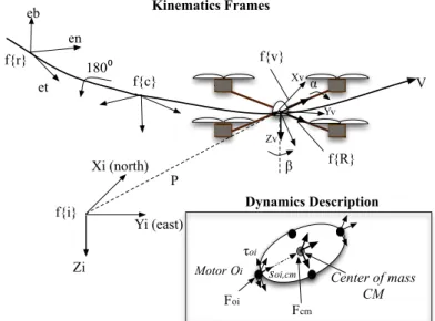
Fig. 3.5 MAV frames of references.
Fig. 3.6 Airfoil parameter design by Blade Element Modeling.
Fig. 3.7 Flow and Forces on the blade.
Fig. 3.8 Blade aerodynamics forces during rotation.
Fig. 3.9 Draganflyer (left) and Micro-Mosquito (right) airfoils-description.
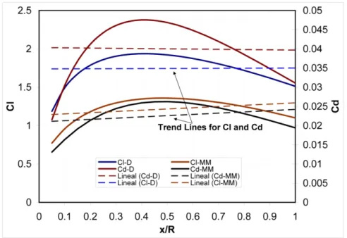
Fig. 3.10 Results for Blade-Element-Theory computation for lift CL-D and drag coefficients CD-D for the DraganFlyer and CL-MM, CD-MM for the Micro-Mosquito, as a function of blade surface distance x/R.
Fig. 3.11 Rotor step response measured at propeller’s shaft.
Fig. 3.12 System setup for output/input data capturing.
Fig. 3.13 IMU response as a function of input parameters (DraganFlyer).
Fig. 3.14 Description of the identification process.
Fig. 3.15 DraganFlyer attitude (angles, rates) identified-model.
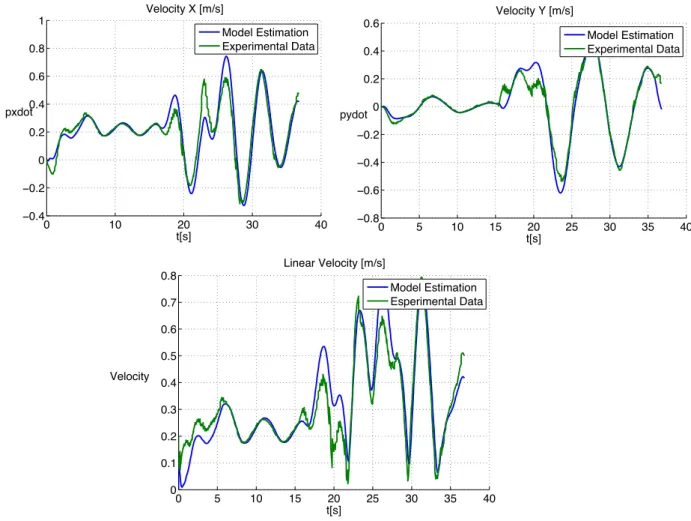
Fig. 3.16 DraganFlyer Velocity identified-model.
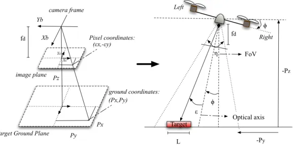
Fig. 3.17 The camera frames of references.
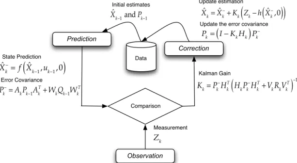
Fig. 3.18 The Extended Kalman Filter framework integrated into the estimation module of the M-ION architecture.
Fig. 3.19. Filtered IMU readings from DraganFlyer MAV (experimental).
Fig. 4.1 The control structure implemented off-board the MAVs.
Fig. 4.2 Front-view of the scenario for controlling altitude based on camera tracking tasks.
Fig. 4.3 PID roll control Simulation.
Fig. 4.4 Simulation: PID controller has to stabilize roll and pitch angles from 45 and 20 degrees to 0 respectively. In addition, yaw orientation must be set starting from 0 to 90 degrees.
Fig. 4.5 The Frenet-Serret Frames.
Fig. 4.6 Simulink Backstepping+FST control testing.
Fig. 4.7 Simulation: Backstepping+FST controller has to stabilize roll and pitch angles to 0. In addition, yaw orientation must be set starting from 0 to
0.8
rad
.Fig. 5.2 The MAV Testing scenario: Vision target tracking (quadrotor example).
Fig. 5.3 The MAV 3D tracking simulator in Matlab: allows to simulate the dynamics behavior of both MAVs and the control strategies provisioned in order to achieve full autonomous flight based on vision tracking.
Fig. 5.4 Hovering maneuver: Position and orientation of the vehicle must remain in zero during the 70 seconds of simulation while hovering altitude of 1m over the target . The M-ION architecture must handle with sensor noises !gyro, !accand the dynamics and aerodynamics nonlinear behavior of the MAV as well
Fig. 5.5 MAV Tracking Target at 1m/s.
Fig. 5.6 Position (Backstepping) and Orientation (Backstepping+FST) control response while tracking at 1m/s showed in Fig. 5.5.
Fig. 5.7 Velocity (Backstepping) and angular rates (Backstepping+FST) control response while tracking at 1m/s showed in Fig. 5.5.
Fig. 5.8 Incremental Tracking Error at diverse target’s speeds using PID control.
Fig. 5.9 Relative tracking error at 0.25m/s between PID VS Backstepping+FST controllers.
Fig. 5.10 Disturbance rejecting testing scenario. M-ION architecture (simulation mode) for indoor navigation based on tracking.
Fig. 5.11 PID control response with wind disturbances of 4m/s and 2m/s in both northing and easting directions.
Fig. 5.12 Backstepping+FST control response with wind disturbances of 4m/s and 2m/s in both northing and easting directions.
Fig. 5.13 X-Y Position Control. The advantage of using the hybrid Backstepping+FST for attitude control is significant for maintaining performance and reliability during Position tracking. The tracking error in position (despite external disturbances) is reduced (compared to PID control).
Fig. 5.14 X-Y Position Control. The advantage of using the Backstepping+FST for attitude control is also significant for maintaining performance and reliability during Position tracking against single backstepping technique. Target’s velocity: 0.3m/s
Fig. 5.15 SIMULINK-based M-ION system blocks for receiving, processing, and sending control commands to the DraganFlyer MAV.
Fig. 5.16 Strong external disturbances addressed during hovering maneuver. In addition, the controller has to deal with sensors noise and other non-desired and non-modeled effects
Fig. 5.17 Attitude control: Comparison between backstepping+FST control against PID controller while maintaining aircraft attitude angles to zero (hovering) despite disturbances addressed as shown in Fig. 5.16.
Fig. 5.18 (GUI provided by Asctech’s SDK ). Numerical data and system supervision.
Fig. 5.20 (GUI provided by Asctech’s SDK ). Waypoint navigation environment.
Fig. 5.21 Hummingbird MAV during autonomous outdoor trajectory tracking based on GPS.
Fig. 5.22 Position control for straight-line tracking based on GPS. Velocity: 1m/s, altitude: 2m over ground, wind speed disturbances about: 4 to 5 m/s.
Fig. 5.23 Attitude, altitude and velocity respond of the MAV during experiment in Fig. 5.22.
The following experiment
Fig. 5.24 Position control for square-line tracking based on GPS. Velocity: 0.25m/s, altitude: 2m over ground.
Fig. 5.25 Attitude, altitude and velocity respond of the MAV during experiment in Fig. 5.24.
Fig. 6.1 The M-ION architecture put into practice: MAV full autonomous navigation is being the result.
1. Chapter I: Introduction
Within the framework of rotary-wing aerial vehicles, the Quadrotor and Coaxial mechanisms are the unique flying vehicles that use the thrust from their motors to provide hover fight capability. Their ability to support large payloads with respect to their size, and the capability to be used within indoors scenarios, make them an attractive vehicle-platforms for autonomous flight research.
As miniaturization of sensor and general hardware technologies move forward [1], these systems are the perfect flying testbeds for approaching new methodologies that apply to both at-scale micro or miniature systems, and so-called: Micro/Miniature Aerial Vehicles Systems -MAVS. Depending on their size, researchers focus on different phenomena, going from miniature aerial systems, to at-scale biological inspired approaches. Despite the differences to regard between both miniature or
micro scales, there is one common research lineup which focuses on developing new techniques (from control and modeling perspectives) that make those systems fully autonomous.
Depending on their flying principle and propulsion mode, MAVs can be classified into multiple categories: fixed, flapping, morphing and rotary wings are the most common mechanisms developed [2], [3]. As usual, the real “Micro” mechanisms (at few centimeter-scale design) have a span less than 15cm with a total weight less than 50 grams, and generally equipped with MEMS sensors, e.g. gyros, accelerometers and piezoelectric actuators. In this sense one can observe that MAVs can be classified within two categories:
1)Micro Aerial Vehicles: at few-centimeter scale design (span<15cm).
2)Miniature Aerial Vehicles: at large-centimeter scale design (15cm<span<70cm).
Fig. 1.1 Aerial vehicles scales.
The differences between the Micro and Miniature scales (see Fig. 1.1) are based on the fact that vehicles of the size of a small bird or even an insect are not still capable of autonomous or even 6-DoF flight, whereas the miniature category provide an ideal platform for testing methodologies that definitively will be the near-future foundation of how to achieve autonomous flying using the micro-scale ones.
In the Micro-category, scientist focus on researching how to approach from bio-inspired at-scale
insects flying aerodynamics [4],[5] at extremely low Reynolds numbers [6], and also developing electronics at that scale of design. As consequence, novel-manufacturing paradigms such as mesoscale fabrication methods [7] and also novel techniques for flying and perception must be regarded in order to achieve the level of efficiency that the millimeter-scale machines will require.
Birds UAVs
Aircraft MAV design
scale
Insects
Mass [Kg]
Wingspan or rotor diameter [m] 1
0.1
0.01 10 100
1 0.01 0.001 0.0001 100 10000
On the other hand, in the Miniature-category, researchers are more focus on developing methodologies [8], [9], [10], [11] that drive those systems into a new full-level of autonomy while performing some mission. The advantages of these systems are related to more payload capacity, which means, more sensing capabilities to address onboard the MAV, e.g. IMU, camera, GPS, laser).
This thesis is oriented towards the development of a robust navigation architecture that approaches autonomous navigation within the framework of rotary-wing Miniature Aerial Vehicles. The goal, is to develop a MAV Indoor/Outdoor Navigation architecture (so-called M-ION) that
facilitates the testing of autonomous indoor or outdoor flight, and also allows the complete modeling, simulation and control of the MAVs. Basically, the objective is to develop suitable methodologies for achieving autonomous Navigation and novel Control techniques that support the level of autonomy that MAVs requires, and guarantee reliable maneuvering.
In terms of navigation, the M-ION architecture provides to the MAVs with indoor and outdoor flying modes. Indoor flight (GPS-denied environments) is subject to vision-based target tracking tasks, which means the MAV must identify a target (e.g. a mobile robot), and using a camera be capable of accuracy maneuvering by tracking the target motion. This indoor flying mode has been just tested under simulation, and future works will provide the full adaptation of the MAVs for achieving autonomous indoor navigation based on the obtained simulation results. On the other hand, outdoor flying navigation is based on GPS data. In this case, experimental autonomous flight has been successfully obtained. Waypoint navigation methodology is used for mission definition, and the M-ION architecture provides to the user with a friendly graphical interface for that purpose.
In terms of control, the attitude control of a MAV is crucial. It provides the required stabilization to perform maneuvering and reliable navigation maintaining 3D orientation. Classical control, such as PID applied to attitude stabilization has being used for awhile. Nonetheless, most of the MAV systems are unable to move in an uncoupled way, and as a result of this under-actuation, standard control techniques do not work well over non-hovering flight [12]. On the other hand, most works [13], [14], [15] whether use non-linear control techniques to improve on MAV flight, but despite the substantial interest of studying dynamics nonlinearities, and design methodologies, little attention has been paid to the impact of aerodynamics effects into the control scheme [16]. This issue has a direct impact in the velocity and acceleration of the system which influences during MAV flight.
To improve on the attitude control under these characteristics, the M-ION architecture uses a hybrid backstepping nonlinear control technique and the Frenet-Serret Theory–FST approach, [17] (Backstepping+FST) that includes estimation of the desired angular acceleration (within the control law) as a function of the aircraft velocity during flight. Details about this novel methodology can be found in [18], [19], [20].
For experimental testing of outdoor navigation, two quadrotor-platforms were used during this thesis. The first one is the DraganFlyer system [21], a commercial quadrotor that can be considered as a flying toy. This vehicle has no control onboard, and teleoperation is based on radio-controller. In order to make this system fully autonomous, prior work consisted on addressing the necessary sensing capacity and the required hardware for that purpose, i.e. placing IMU, GPS, wireless data links, and power management [22]. Subsequently, upcoming work was related to implement the M-ION architecture using a Simulink-based environment that provides the stages of simulation and autonomous flight.
The second quadrotor-platform is the Hummingbird system [23]. This is also a commercial product with a highly integrated onboard data processing and all the necessary sensors for autonomous operation. This prototype was developed by Ascending Technologies GmbH1, which also provides
a powerful Software Development Kit -SDK that allows the user to develop own-software based on a C++ environment. For this system, the M-ION architecture has been embedded with the SDK libraries provisioned. In addition, a friendly Graphical User Interface -GUI has been also developed using the TcL/Tk framework. This GUI allows the user to supervise the mission and to analyze flight-data in real time.
Figure 1.2 shows the concept of the off-board integration of the M-ION architecture for both quadrotor systems. Note the architecture is an interplay of hardware and software, where navigation and control issues are strictly dependent on the sensors onboard. Because of the off-board integration, the whole system requires a PC-station for managing computation and communication issues.
Another prototype used in this thesis is a coaxial mechanism: The Micro-Mosquito. Unlike the previous quadrotor systems, this MAV is a flying toy without any sensing capacity onboard. Due to its poor payload capacity (about 15 grams), the work of addressing IMU, camera, datalink, etc, represent a tremendous challenge from the electronics miniaturization perspective. Despite these drawbacks, this thesis takes advantage of this prototype in order to propose a mathematical model that allows the use of the M-ION scheme for analyzing the control (under simulation) of this mechanism. Future works will be focused on solving the hardware-constrains of this MAV.
Fig. 1.2 M-ION architecture integration for the two experimental platforms used in this thesis.
In conclusion, the development of this thesis requires to approach several problems related to:
๏ Modeling and simulating quadrotor/coaxial dynamics and aerodynamics effects. ๏ Modeling sensing onboard: IMU, camera, GPS.
๏ Identifying and validating quadrotor model via experimental testing.
๏ Implementing data acquisition, filtering and estimation stages to achieve sensor fusion. ๏ Improving over existing linear-control in order to achieve autonomous flight.
The solution of those challenging problems are presented in next chapters. For instance, next subsection reviews the motivations, goals, and contributions of this work based on the state-of-the-art survey of this topic.
1.1. Motivation
This thesis started in 2008, a time at which the robotics community was showing a full interest related to Micro Aerial Vehicle-MAV development. The scientific challenge in relation to achieve full autonomous navigation, MAV design and control and the lack of existing reliable commercial MAV autopilots is very motivating. On the other hand, the Robotics and Cybernetics Group at the Universidad Politécnica de Madrid has been researching about the UAV topic during the last
PC-station M-ION
Simulink-based C++ basedM-ION
years. Some projects related to mission planning and control of helicopters have been the center of the research and developments obtained for instance. However, as technology move forward, the need of miniaturizing robots is imminent for a new era for micro-applications. The topic of modeling and controlling miniature Aerial Vehicles has not been treated yet.
Despite a new era of robust and small sensing technologies (Micro Electro-Mechanical Systems MEMS) and small actuators that facilitate MAV design and construction nowadays, the control of these systems is still a challenging goal. For this reason, this thesis approaches the problem of achieving autonomous navigation using a rotary-wing MAV mechanism. The issue of dynamics modeling, nonlinear control, sensor integration and fusion represent an interesting and challenging goal.
1.2. Aim and Scopes
This research work is carried out as a part of the project titled: FRACTAL: Fleet of Cooperative Terrestrial and Aerial Robots, sponsored by the Spain Ministry of Education and Science (DPI 2006-03444).
The aim of this thesis work is to develop a MAV navigation architecture (so-called M-ION) for achieving autonomous flight. Basically the objective is to develop suitable methodologies for
Navigation and novel Control techniques that support high level of autonomy during flight.
In this sense, the scopes of this work are summarized as follows:
๏To overview the state-of-the-art of MAV systems, highlighting how to achieve fully autonomous flight based on sensing capacity.
๏To obtain a complete six Degree of Freedom- DoF dynamics modeling of the vehicles in matter, studying inertial and aerodynamics effects. In addition, mathematical models of the sensors to be used: camera, IMU, and actuators onboard.
๏To implement the concept of the M-ION architecture based on hardware sensor fusion and the models previously defined.
๏To introduce a novel nonlinear control technique called: Backstepping+FST as a single approach for attitude control. To implement basic PID control for position control.
๏To merge dynamics/aerodynamics models, actuator models, sensors models, sensor filtering and fusion, and Backstepping+FST control model within the M-ION architecture.
๏For the DraganFlyer quadrotor, to implement the M-ION architecture using Simulink-Matlab environment. The architecture must include:
‣ Simulation of indoor navigation based on visual tracking tasks.
‣ Outdoor mission control based on GPS data (full position and attitude control), including user supervision using a joystick device.
๏For the Hummingbird quadrotor, to implement the M-ION architecture using the Asctech C++ SDK environment. The architecture must include:
‣ Outdoor mission control based on GPS data (full position and attitude control), including user supervision using a radio-control device.
๏For the Micro-Mosquito model, to implement the M-ION architecture using Simulink-Matlab environment. The architecture must include:
‣ Adaptation of models and control for the coaxial mechanism.
๏Final experimental results conducted on the DraganFlyer and the Hummingbird quadrotor will show the capabilities of the control architecture in relation to stationary flight and high maneuverability during normal flight. Furthermore, simulation experiments using the Micro-Mosquito will provide foundations for future developments using these mechanisms.
1.3. Document OutLine
This thesis document is organized as follows:
First of all, Chapter 2 presents a review of the specialized literature found in the state-of-the-art of MAV systems. This survey reviews the two MAV categories previously mentioned: Real approaches at-scale rotary wing Micro-vehicles, and Miniature-vehicles. Furthermore this section also includes a briefly description of the challenging problems to solve and the approaches to be introduced.
Chapter 3 introduces the fundamental concepts of the classic mechanics that are related to the dynamics modeling of Miniature Aerial Vehicles. Equation of motion are presented using rigid-body physical description based on spatial algebra operators. Hence, dynamics models for the quadrotor and coaxial systems are obtained as a function of their morphology. Further analysis of MAV aerodynamics are also presented and included within the dynamics frame. In addition, this section also presents the validation of the mathematical dynamics modeling of the quadrotor via system identification methodology.
Once the whole vehicle’s components are tackled into modeling, Chapter 4 presents the control approach. A proposed control structure using a novel backstepping+FST for attitude stabilization is presented and then compared against linear PID controller.
Chapter 5 shows the simulation and experimental results in terms of autonomous navigation and controller performance, for indoor (simulation) and outdoor navigation (experimental). Results will confirm that the M-ION approach is suitable for achieving MAV navigation, and will show that the hypothesis of improving attitude stabilization using the Backstepping+FST methodology is indeed correct.
2.
Chapter II: Micro Aerial Vehicles Literature
Overview
In the field of sensing technologies, industry can currently provide a new generation of integrated Microelectromechanical Systems (MEMS) that allows the production of machine components with sizes in 10-6 meter range [24]. Using this MEMS technology, very small accelerometers, gyros and magnetometers are also produced, causing the production of smaller inertial navigation systems. As a result of this improvement in technology, very small aerial vehicles are being developed around the world (see Appendix A for different state-of-the-art MAV characteristics).
Despite these new technologies facilitate the design and construction of these small flying machines (MAVs), the control for achieving autonomous navigation remains an interesting branch of research. Most of the current projects focus the attention in relation to the MAV design problem (materials, hardware equipment, sensor development), and many others focus on the MAV control issues.
Next subsections reviews the state-of-the-art development in both Micro and Miniature categories, highlighting the research efforts in relation to autonomous navigation architectures based on the sensing capabilities provisioned to the vehicles and the control techniques that handle the flight behavior.
2.1. Micro Aerial Vehicles: small-scale approach
2.1.1. Micro-Flying Robot from EPSON Company
The Micro-Flying Robot II (MFR-II) developed by EPSON Company [25] is the best worldwide example of a coaxial-type flying robot. Its overall weight is of an unprecedented 12.3 grams with a rotor span of 136mm and 85mm height. Two ultrasonic motors are used to actuate the propellers. Translation is controlled by linear actuators, which shift the center of mass of the vehicle. Sensing is provided by an altitude sensor, a MEMS gyro and a small CMOS based camera. In addition, the vehicle is equipped with onboard CPU as well as bluetooth wireless communication. The picture of the MFR-II is depicted on Fig. 2.1.
Fig. 2.1 EPSON’s Micro-Flying Robot II.
Epson made the robot lighter by developing a new gyro-sensor that is a mere one-fifth the weight of its predecessor, making it the world's smallest and lightest 6-DoF gyro sensor. As for the challenge of independent flight, Epson brought its many years of micro-mechatronics experience to bear in realizing the development of a linear actuator with faster response time and a high-precision attitude control mechanism, and a flight path control and independent flight system (primarily for hovering).
In addition, Epson added an image sensor unit that can capture and transmit aerial images via Bluetooth wireless connection to a monitor on land. Epson was assisted by Chiba University's Nonami (Control and Robotics) Laboratory in developing the control system for independent flight. The company also received advice on the rotor design from the Kawachi (Aeronautics and Astronautics) Laboratory at the University of Tokyo.
2.1.2. The Mesicopter from Stanford University
A team of researchers from Stanford University, SRI, and M-DOT Corporation proposed to build the Mesicopter [26], a centimeter-size electric helicopter designed to stay airborne while carrying its own power supply. The Mesicopter is a pioneer application in relation to aerodynamic design concepts and novel fabrication techniques, including solid free-form fabrication and VLSI processing steps. These techniques may ultimately allow the mesicopter to be scaled down to millimeter dimensions. Significant challenges are anticipated in the areas of materials, battery technology, aerodynamics, control and testing.
Fig. 2.2 Mesicopter Vehicle from Stanford University.
The Mesicopter prototype, shown in Fig. 2.2, has four motors with 1.5cm diameter and mounted on a constrained arm, hence it is not capable of 6-DoF flying compared to the MFR-II from EPSON. it is used just to demonstrate lift off. It weights 3 grams and Stanford researchers focus on understanding aerodynamics at extremely low Reynolds numbers.
2.1.3.
The Nanoflyer from ProxFlyer Company
Fig. 2.3 The Nanoflyer from Proxflyer Company.
The Nanoflyer shown in Fig. 2.3 is capable of radio-controlled operation, lacking of autonomous flight. It has a rotor diameter of 85mm and airframe of 80mm long, and a weight of 2.7 grams (including battery and control). The benefits of this vehicle is that it is absolutely stable without the use of any gyro or autopilot.
2.1.4. The Micro Mosquito 3.0 from RCtoys
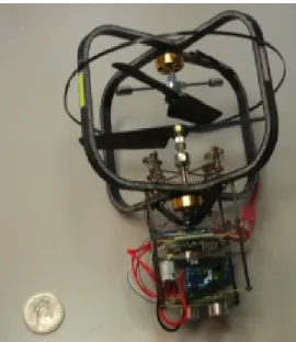
The Micro Mosquito 3.0 Indoor RC helicopter [28] is only 6.5 inches long with a rotor diameter of 6.375 inches and 20 grams weight. Based on the award-winning BladeRunner coaxial rotor design, the Micro Mosquito 3.0 helicopter flies in all directions with 3 channel digital proportional control. Unfortunately, this toy is only capable of supporting payloads less than a 15grams, which makes it unsuitable for achieving autonomous flight. The Micro Mosquito prototype is shown in Fig. 2.4:
Fig. 2.4 The Micro Mosquito by RCtoys.
2.2. Miniature Aerial Vehicles: medium-scale approach
2.2.1. The DraganFlyer X-pro
Fig. 2.5 the Draganflyer X-Pro.
2.2.2. The Quattrocopter from the EADS
The Quattrocopter [30] is an impressive quadrotor micro air vehicle (MAV) designed by European Aeronautic Defense and Space Company (EADS). The Quattrocopter is about half a kilogram in weight and measures 65cm in size. It can fly for 20 minutes with 1 km of operating range and has 50% payload capacity to carry small spy camera and other sensors. It is the only commercial quadrotor UAV designed for industrial and defense applications. The onboard controller, called micro-avionics autopilot, includes six inertial sensors, GPS, air-data sensors and micro-controller. The Quattrocopter is shown in Fig. 2.6.
Fig. 2.6 The Quattrocopter from the EADS.
2.2.3. The STARMAC from Stanford University
computers running Matlab to generate path trajectories for each flying vehicle. Outdoor flight tests have been carried out to demonstrate the performance of control algorithm. A picture is shown in Fig. 2.7.
Fig. 2.7 The STARMAC from Stanford University.
2.2.4. CoaX from Skybotix Technologies
Skybotix [32] is a Swiss Company focused on developing autonomous navigating micro aerial vehicles and related technologies. The CoaX prototype has a mass of 320 grams, span of 34cm, and 25 minutes flight time. This includes the coax board with IMU, Bluetooth (or ZigBee), pressure sensor, down-looking sonar, side looking sonar(s), 2.4GHz receiver+RC, a color camera, Gumstix Overo (ARM), wifi, Low-level control, API for high level control, and bluetooth bootloader for the microcontroller. The!CoaX!was!developed!in!collaboration!with!the!ETH!Zürich.
Fig. 2.8 The CoaX platform from Skybotix Technologies and the ETH Zürich.
2.2.5. The DraganFlyer from DraganFly Inc.
The DraganFlyer shown in Fig. 2.10, was the first Draganflyer commercial platform developed by
Fig. 2.9 The Draganflyer by DraganFly Inc.
2.2.6. MuFly: Fully autonomous Micro Helicopter from ETH Zurich.
The European project muFly [33] was born in this context in July 2006; it targets the development and implementation of a fully autonomous micro-helicopter, with a span of 12cm and a mass of 30g. The project shall demonstrate innovative approaches and technologies in: 1) system level design and optimization, 2) design of miniature inertial units and omnidirectional vision sensors, 3) miniaturized fuel-cells, 4) micro piezoelectric actuators and 5) low processing power control and navigation algorithms. The final system is expected to find applications in rescue missions and surveillance of buildings. As shown in Fig. 2.11, the vehicle is 120mm of rotor span and endurance of 4 minutes flight time. It incorporates mini-camera, altitude sensor, onboard CPU, IMU, motor, propellers, a linear actuator, and featuring attitude, altitude control, forward flight and indoor operation.
Fig. 2.10 The MuFly robot from ETH University.
2.2.7. AscTec Hornet from Ascending Technologies
developed for a competition for Micro Air Vehicles "MAV08". It can be used in all applications where small dimensions and little weight are more important than long flight times with heavy payloads.
Fig. 2.11 The AscTec Hornet Hexacopter.
2.3. General Research related to MAV autonomous flight control
Considerable amount of research work has been done in developing various control methodologies for general Miniature Aerial Systems. In terms of MAV design and control, Samir Bouabdallah et al, [34] has tackled the quadrotor design problem by introducing a new methodology that optimizes the system resources. The result is called the OS4 platform, a light miniature quadrotor with a high level of autonomy. In terms of control, they have compared the stability performance of the OS4 using classic PID and LQ techniques. Based on that, a combined model based on predictive controller (MBPC) was derived for testing autonomous flight.
For indoor navigation, Altug et al. [35] uses an offboard camera to determine the pose of a quadrotor helicopter in simulation and restricted flight. Simulations show results for a feedback-linearization control approach as well as a backstepping method. All pose estimation is computed offboard using an overhead camera, and a tethering system constrains motion in the x- and y-directions. Thus while this is a good demonstration of control methodologies, it was not proven to be an effective position control scheme on a truly autonomous system. In a later effort [36], a dual camera approach is employed to provide a more reliable pose estimate and results are collected on a tethered system.
More promising flight results are obtained by Roberts et al. [37] in which a quadrotor is outfitted with infrared triangulation sensors that allow the vehicle to navigate hands-off for extended periods of time within an enclosed environment. The infrared sensors maximize their distance from nearby walls allowing the vehicle to hover in a fairly tight radius. However, the implementation of the special infrared sensors only appears to work in fully-enclosed areas. Thus, this particular application has not been shown to have widespread applicability to real-world situations.
Exploring other methods, J. Dunfied, et al, [38] have developed a neural network based controller to hover a quadrotor vehicle. The research work includes generating training data while flying the vehicle manually, training the neural network offboard, and generating similar neural network controller into a Motorola micro-controller. Two tilt sensors, one compass and three piezoelectric gyros are used as onboard sensors to provide training data and feedback to the controller. A two layer feed forward back propagation network, with log sigmoid transfer function has been used.
isolation, and recovery [39]. Using a very precise VICON camera system, they demonstrate the ability to control several off-the-shelf quadrotor vehicles simultaneously. The VICON system is capable of sub-millimeter position accuracy and sub-degree attitude estimation. Using LQR controllers based on linear dynamics, very stable flights of quadrotors are demonstrated. This allows their research to focus on higher level tasks such as multi-agent tasking and health monitoring for persistent surveillance and mission planning. However, sophisticated camera systems like VICON are expensive and require off-board cameras, thus they do not represent real-world position sensing capabilities.
In conclusion several research has been carried out involving the autonomous flying goal. Ones focus on visual-perception approaches, others use big-scale MAVs (more close to UAVs) to focus on high level mission planning or cooperation, whereas others approach to the design and control problem. Despite all the efforts, there is no concise work that merge into a single solution the indoor and outdoor autonomous navigation issues from a control perspective. Most of the works that focus on navigation, lack of robust controller that guarantee MAV maneuverability.
This thesis approaches the problem of MAV navigation involving robust control techniques that enhance MAV flight. Next subsection reviews the MAV configurations to study: rotary-wing quadrotors and coaxial mechanisms, highlighting the advantages of these kind of system over other MAV configuration.
2.4. MAV Comparison and Configurations
In general, aerial vehicles can be classified depending on their flying principle and propulsion mode. Table I provides a comparison between different flying principles from the miniaturization point of view. One can easily conclude that Vertical Take-off and Landing -VTOL systems like helicopters have an unquestionable advantage compared with the other concepts in terms of their unique ability for vertical, stationary and low speed flight.
Table I.
MAV Configuration Comparison.
!
NanoFlyer-Proxflyer CompanyWeightIMU Cam Control
3.3g No No No
Flight Time Span
1 min. 60mm
Micro-Mosquito – RCtoys
WeightIMU Cam Control
20g No No No
Flight Time Span
7 min. 160mm
!
Mini Flying Robot- EPSONWeightIMU Cam Control
12.3g Yes No VTOL
Flight Time Span
3 min. 85mm
!
CoaX 2- ETHWeightIMU Cam Control
200g Yes Yes Yes
Flight Time Span
20 min. 300mm
!
Mesicopter- Stanford UniversityWeightIMU Cam Control
80mg No No No
Flight Time Span
Less 1 min. 35mm
!
Flying Alice- ETHWeightIMU Cam Control
20g Yes No Yes
Flight Time Span
5 min. 137mm
!
ProxdynamicsWeightIMU Cam Control
10g Yes Yes Yes
Flight Time Span
Less 1 min. 100mm
!
Micro blimp- EPFLWeightIMU Cam Control
400g Yes Yes Yes
Flight Time Span
!
MFI-Berkeley UniversityWeightIMU Cam Control
100mgNo No No
Flight Time Span
Less 1 min. 25mm
!
DraganFlyer-DraganFly Inc.WeightIMU Cam Control
450g No Yes No
Flight Time Span
30 min. 630mm
Micro Glider- Berkeley U.
WeightIMU Cam Control
2g No Yes Yes
Flight Time Span
3 min. 100mm
!
CoaX- Skybotix technologiesWeightIMU Cam Control
320g Yes Yes Yes
Flight Time Span
25 min. 340mm
!
Insect- Harvard UniversityWeightIMU Cam Control
60mg No No VTOL
Flight Time Span
Less 1 min. 30mm
!
MuFly- ETHWeightIMU Cam Control
30g Yes Yes Yes
Flight Time Span
5 min. 120mm
!
Wasp MAV- DARPAWeightIMU Cam Control
170g Yes 2-c+GPS Yes
Flight Time Span
1:47 min (record) 320mm
!
Quattrocopter - EADSWeightIMU Cam Control
500g Yes Yes Yes
Flight Time Span
20 min. 650mm
For future VTOL MAV systems, the coaxial and the quadrotor are the most promising ones. Basically, their simple mechanical structure, large payload capacity in relation to their size and weight, and their production costs, make them an attractive MAVs target. Next subsection reviews both rotary-wing mechanisms in detail.
2.4.1. Coaxial Mechanism
The development of full-scale coaxial helicopters was historically slower than the one of single rotor. This is mainly due to the incredible complexity of their swashplate mechanisms. In the coaxial configuration, one propeller is located above the other with a common shaft. The rotors turn in opposite directions, which removes the need for a tail rotor, and makes the helicopter a lot more compact. Typical coaxial MAVs use the residual torque, due to angular speed difference between the two rotors to rotate the helicopter vertically, left or right. Increasing or decreasing the angular speed of the rotors simultaneously permits climbing and descending. Finally, by using simplified swashplates or by shifting the center of gravity, it is possible to control rotation about the longitudinal and the lateral axis and thus control horizontal motion. Coaxial configuration fits remarkably well the requirement for MAVs. Fig. 2.12-letf shows the coaxial concept.
2.4.2. Quadrotor Mechanism
Fig. 2.12 The Coaxial and the quadrotor rotary-wing MAV concepts.
2.5. Contribution of this work
This thesis focuses on the modeling and control problems of autonomous micro aerial vehicles with application to a quadrotor and a coaxial rotary-wing systems. The contribution of this work lies in three fields.
๏ MAV-platform setup: To achieve autonomous flight, the experimental quadrotor platforms, the Draganflyer and the Hummingbird have been hardware-modified in order to include the required sensing and communication capabilities.
๏System Modeling: the goal is to obtain a 6-DoF mathematical representation of the mechanical system for achieving full control. Based on first principles, spatial algebra is introduced for optimizing the dynamics equation on motion that includes aerodynamics effects, motor dynamics, as well as sensors onboard models.
๏ System Control: the aim is to apply a novel nonlinear control technique to improve on attitude stabilization while performing autonomous navigation.
2.5.1. MAV-platform setup
As mentioned before, the MAVs used in this thesis required of hardware modification in order to include the required sensing and communication capabilities that achieves autonomous flight. Starting with the Draganflyer quadrotor (which was practically a flying toy with only R/C radio link to be manually handled), previous work in [22] aimed to modify its structure and sensing capacity that turned the Draganflyer into a flying robot platform (see Fig. 2.13).
In terms of sensing capacity, autonomous flight requires -at least- an Inertial Measurement Unit -IMU that senses angular rates and accelerations, and a Global Position Unit -GPS that determines the three-dimensional position of the system (outdoor navigation). Using this sensor fusion, 6-dimensional control is possible. In this sense, a XSENS-IMU1 was used to provide angular feedback to the control system. Appendix B shows some IMU technical details and the initial tests for sensing roll, pitch and yaw angles and rates of the vehicle.
Fig. 2.13 DraganFlyer platform setup process.
Besides the IMU, a Ublox-GPS2 sensor was also embedded into the quad-platform. Appendix B shows the details of the GPS-unit, including the antenna and some initial testing for checking GPS satellite connections. In terms of communication, two bluetooth devices have been used for wireless datalink of IMU and GPS data to the PC-station. In the case of the IMU, a RS232 interface Firefly-BT device is used, operating at 115200 Bp/s, with a data-package of 8-bits (including 1-bit for protocol control). For the GPS, another Firefly-BT device is used but a MAXRS232 additional device was needed for connecting the data-link to the PC station.
For the Hummingbird quad-platform, the only modification was related to mounting the camera onboard. This MAV has all the necessary sensing and communication capacity onboard. The system-setup for this quadrotor was related to the software that enhances user system-handling. Next sections will review the details of the software provisioned. Finally, Appendix C shows technical information of the hardware components already provisioned by the Hummingbird quadrotor and some plots of the mentioned GUI-software enhancement.
To visualize a sneak peek idea of the entire system-setup process, Fig. 2.14 reveals the initial concept of the hardware components that allows the M-ION architecture turning the MAVS into autonomous navigation systems (including user-supervision within the closed-loop).
Fig. 2.14 Entire System setup. General Hardware-architecture.
Bluetooth Links GPS
IMU Battery
GPS antenna
Electronics
New-Frame Structure H/W-modified DraganFlyer
Carbon-fiber tubes light-wood
DraganFlyer Toy
USB Interface
PC-station M-ION architecture
Bluetooth Links GPS
IMU GPS antenna
R/C control
GPS antenna Camera+WiFi datalink
Battery Proccesor+IMU
BT DataLink
Video link 30 fps
DataLink X-Bee 2.4 Ghz, pair.
Control Firefly Bluetooth
IMU-datalink ARF52 Bluetooth
GPS-datalink
User Supervision
User Supervision
2.5.2. System Modeling
The modeling of both quadrotor and coaxial systems was developed in successive steps. The objective was to find a set of Equation of Motion-EOM that described the vehicle dynamics in the 6-dimensional space. The first step consisted on studying the spatial algebra operators [40] useful for stacking the physical variables that define the motion of the vehicle within the tridimensional Euclidean space. The advantage of using this algebra for developing EOM relies on their variable-compactness and insight of the physical behaviors that rule the MAV dynamics: Gyroscopic forces, Coriolis accelerations, etc. Based on MAV morphology (see Fig. 2.12), theoretical mathematical models were used to define their non-linear dynamics. Once the dynamics EOM was established, the introduction of several effects like friction forces due to aerodynamics, motor dynamics, propeller rolling moments, etc were also incorporated within the EOM.
The second step was to develop a Simulink-based simulator, that allowed to observed and analyzed the proper behavior of the MAVs during flight. This simulator was embedded as a module-component of the M-ION architecture, so-called: simulation stage. A 3-dimensional GUI was implemented to see the MAV maneuvers during flight. In conclusion, the system models were also embedded within the simulation-stage M-ION architecture, which main modules-components are: Dynamics EOM block, Motor dynamics block, and Aerodynamics block.
The third step was to identified the Draganflyer-dynamics via experimental testing. This identification process was performed offline the M-ION architecture and is not a component of it. Based on Autoregressive Moving Average (ARMA) methodology, several experimental testing was performed to link output and input signals that allowed to find an approximate model of the real-system. This step allowed to validated the EOM for both angular rates and linear velocity quadrotor behavior (key to future implementations of control algorithms).
For the fourth stage of the system modeling process, mathematical models of sensors onboard were also developed. Basically, camera equations that relate the image within the frame of reference of the camera, and IMU equations that describe its sensing properties. Sensor fusion was implemented using an extended Kalman filter. This sensor-module allowed to enhance the robustness of the simulator, and to feedback system information to the closed-loop control module.
Finally, the last stage consisted on developing and incorporating robust control algorithms based on a novel methodology developed in this thesis called: Backstepping+FST. Next subsection explain this issue.
2.5.3. System Control
An important aspect of this thesis was dedicated to testing and proposing a reliable control approach for both quadrotor and coaxial MAV systems. Using the simulation-stage of the M-ION architecture, several control testing was performed in order to obtain a control law that really takes into account the most physical phenomena behaviors. In the first attempt, simple PID controller was tested on the system. Simplified linear models were extracted from the EOM for PID control purposes. Simulation results showed that PID control was suitable for attitude and position control during hovering maneuver. However, during high-speed maneuvering, PID control showed poor tracking and non-proper attitude stabilization during flight.
consisted on typical target tracking using visual capability, next section will explain them in detail. From this simulation results, we found that a missing term within the backstepping control law was missing. This term must contain the effects of the kinematics variation of the vehicle during the maneuver, specifically, angular velocity and acceleration. Based on this fact, an hypothesis was raised. This hypothesis establishes that the impact of kinematics angular rates and accelerations must be included as a function of the control law. In this sense, a new term called “a desired angular acceleration command” was addressed into the control scheme.
3. Chapter III: The MAV System Modeling
The goal of this section is to define physical Equations of Motion -EOM that describes the dynamics and aerodynamics of the MAVs involved. This modeling process can be described as follows (Chapter 3 structure):
๏ Newton Euler fundamental formalism is used to describe dynamics effects. In this sense, the whole structure of the MAVs is supposed to be rigid, and consequently, rigid body dynamics applied to a single body are used as a foundation to define the EOM.
๏ To properly operate physical quantities, different kinematics frames of reference are introduced. For the MAV-vehicle/body, 2-frames of reference are used: 1). The Vehicle-frame f{v} that coincides with the Center of Mass -CM Vehicle-frame of the vehicle/body, and 2). The joint frame {O_i} located at each motor in the border of the vehicle. In the case of the quadrotor, four-{O_i} frames are used for each rotor, and for the coaxial concept, just one-{O_i} is placed on the main rotor propeller (see Fig. 3.1 to visualize these frames). For the entire system, another 3-frames of reference are used: 1). The fixed Inertial frame f{i}, 2). The Frenet-Serret frame f{r} and 3). The Rotated Frenet frame f{c}. The Kinematic-section of this document will explain these frames in detail.
๏ For aerodynamics modeling, blade Element Theory is used as a function of the propellers characteristics. This model relates air density, lift and drag coefficients based on blade momentum. We assume that thrust and drag are proportional to the square of propeller’s speed.
๏ Based on experimental tests, motor dynamics are identified and regarded into modeling. ๏ Likewise, identification and validation of the DraganFlyer quadrotor dynamics is also
presented based on Autoregressive Moving Average (ARMA) methodology.
๏ Finally, sensor fusion is obtained using Kalman Filter theory, and the modeling-stage of the M-ION architecture is established.
Before presenting this modeling process, next subsection briefly introduces a system description overview of the platforms: The draganFlyer and Hummingbird quadrotors, and the Micro-mosquito coaxial rotary-wing MAVS.
3.1. System Description, Advantages and Drawbacks
The Draganflyer (See Appendix B) is a radio-controlled four-rotor VTOL vehicle. The operator of the radio controller has four channels of input to control the motion in the 6-dimensional space. Unlike a conventional helicopter, where lift force generated by rotors change direction by modifying the rotor pitch angle, the motion of Draganflyer can only be controlled by varying the speed of the four rotors, as the pitch angle of rotors is fixed.
Normally, the quadrotor is steadily becoming a favorite aircraft among research groups due to its decoupled longitudinal and lateral dynamics, its payload capacity, and its relative simplicity of design. However, the Draganflyer is difficult to control even by a skilled operator. This is partially because of its highly coupled dynamics, but the main reason of Draganflyer’s instability is the deficiency of its structure. The helicopter will remain stable hovering if the four lift forces are the same and the sum of these forces equals the gravity force. However, any difference in rotor speed or rotor pitch angle or even rotor size (which has great possibility to happen due to manufacturing inconsistency or assembly fault), can cause force or torque unbalance. This issue result on undesired angular motion.
will cause the craft to yaw to the right due to the imbalance in torque between the right-left motor pair and the front-back pair. The roll will cause the craft to translate to the right, as the rotor forces are now directed toward the left as well as down. The yaw will cause the translation to change direction toward the front. The induced torques from the four rotors cancel through the airframe, placing considerable stress on it. This is a significant weakness of its design, and results in both distortion of the frame during flight and fixers coming loose due to the resultant vibrations. The small size, highly coupled dynamics, low air drag on the fuselage and high air drag on the rotors pose significant challenges in the control of this quadrotor.
In terms of control, mapping the commands from control space to force space requires a model of the forces and their interactions. Each motor produces a force F and torque ! . For the rotational force-components, the rolling torque is produced by the forces of the right and left motors: "2 and
"4 respectively and similarly, the pitching torque is produced by the forces of the front and back
actuators: "3 and "1. Figure 2.12 shows this issue.
Another quadrotor platform used is the hummingbird. This MAV has many advantages: is extremely compact (as resulted from a well-design methodology), very stable during flight, with all necessary sensory capabilities, among others. Due to its size and stability is very suitable for indoor navigation. Once the control problem of the Draganflyer has been solved, the control of the hummingbird will be an easy task. (See Appendix C for additional details)
On the other hand, the Micro Mosquito MAV (see Appendix D) flies in all directions using a 3-channel Radio control. This MAV can fly up, down, forward, reverse, turn left and right, and even hover on the spot. As mentioned, the coaxial structure provides enhancements related to stability and controllability. However, its payload capacity (15 grams) constrain the MAV to address powerful sensing capabilities. The advantage of its coaxial structure is mainly suitable for indoor navigation. Designing control algorithms that achieves even more stabilization of the vehicle do not represent a significant challenge. However, due to its poor payload capacity, the challenge is to develop electronics (sensors, power-boards, batteries, etc) that fit within the MAV. This lack in sensory and computational power capacity requires of simple algorithms that can be computed onboard. For this reason, modeling and evaluating this kind of system under simulation will provide the required foundations to regard during future developments. (See more technical details in Appendix D).
3.2. General Overview of Single Rigid Body Dynamics
3.2.1. Basic Concepts
This chapter deals with the description of the fundamental concepts of the classic mechanics that are related to the rigid body dynamics modeling, establishing an appropriate mathematical representation of the physical quantities that are involved in that process. First of all, the simple rigid body Equations Of Motion - EOM are introduced using the spatial operators [40] useful for stacking the physical variables that define the motion of the bodies within the tridimensional Euclidean space. Within this space, an object which cannot be deform by the forces that are acting on it, is known as a Rigid Body. This means a rigid body is a collection of particles constrained of keeping a fixed distance between each other. Despite its non-exactly mathematical modeling, is possible to approach the dynamics modeling of many objects through the theory of rigid bodies.
operator for defining the classical physics EOM, adapting this theory to our system. The first aspect to review is the elements that compose the dynamics description of the body. These are linear operators which domains and ranges consist in forces, momentum, velocities and accelerations. This operators also allow concise and systematic formulations of the Newton’s Euler EOM and the development of efficient computational algorithms for their computation.
3.2.2. The 6-dimensional Spatial Notation
Frame-Oi Center of mass
Frame-CM Ycm Xcm Zcm soi,cm Fcm Foi
!
oiFig. 3.1 Operators considered for dynamics modeling.
Assuming from Fig. 3.1 that frame-Oiis a point located on the rigid body, soi,cm the vector that joints
the extreme border Oi with the rigid body’s center of mass CM, the translational and angular
velocities (v, w) and forces (f, !) respectively at any point on a body in "3 are related as (in this case we take the frame-Oi and CM):
In terms of spatial algebra, the physical quantities from Eq. (3.1) are represented as a 6x1 column vectors, and each incorporates the appropriate angular and translational components stacked together. Those terms now in "6 with respect to the CM of the body are:
As mentioned, the soi,cm vector in "3 represents the position vector from frame-Oito the CM of the
body (see Fig. 3.1) and its 6-dimensional operator representation is is denoted as Soi,cmin "6 as:
where U # "3x3 is the identity operator, and
s
!
oi,cm # "3x3 is the skew symmetric matrix
corresponding to the vector cross product operator of soi,cm:
This skew-symmetric matrix has some interesting properties (for any point in "3) which will be
useful for the mathematical treatment of the EOM. Those properties are presented in Eq. (3.5) as: (3.1) !cm =!oi
vcm=voi+!oi"soi,cm foi = fcm
#oi =#cm+soi,cm" fcm
(3.2)
Vcm= !cm vcm " # $ $ % & '
', V!cm=
! !cm ! vcm " # $ $ % & '
', Fcm =
(cm fcm " # $ $ % & ' '
Soi,cm= U s!oi,cm
0 U ! " # # $ % & & (3.3) (3.4) !
soi,cm =
0 !sz sy
Using this spatial notation in Eq. (3.1) is rewritten in order to relate the physical quantities at any point of the rigid body and its center of mass, yielding:
In Eq. (3.6) the spatial velocity at the center of mass of the body may be written in terms of any other point (in this case frame-Oi), using the vector between these points: soi,cm. Taking the first
derivative of the set of spatial velocities in Eq. (3.6) with respect to time, the set of spatial accelerations are:
The second term of the Eq. (3.7) represents the Coriolis/centrifugal accelerations, which both are dependent of the velocity. Decomposing this term yields:
Note that Coriolis and centrifugal accelerations in Eq. (3.8) just have a translational effect over the EOM. Other interesting aspect is the fact that the derivative with respect to time of any position vector is equivalent to the linear product between its angular velocity and itself. For explaining this fact, let suppose a frame of reference denoted by {f}* that is rotating with respect to a Q*-axis with an angular velocity ! (defined as a vector of magnitude ! directed along the Q*-axis). If a
vector denoted as r is fixed with respect to this frame of reference, its derivative is null, but its derivative with respect to other frame of reference is given by:
To demonstrate Eq. (3.9), Fig. 3.2 shows the derivative respects to time of a rotating:
Fig. 3.2 Derivative of a rotating frame with respect to time.
(3.5) !
pi,j.pk,l=pi,j!pk,l
"p!i,j.pk,l=p!k,l.pi,j=pk,l!pi,j !
pT
i,j="p!i,j
Vcm=SoiT,cmV oi
Foi =Soi,cmFcm
(3.6)
!
Vcm=SoiT,cmV!
oi+S!oi,cm
T V
oi (3.7)
(3.8)
boi=S!
oi,cm
T V
oi =
!
U 0
!s"!oi,cm U!
" # $ $ % & ' ' (oi voi " # $ $ % & ' '= 0 !("ois"oi,cm("oi
" # $ $ % & ' '= 0 "
(oi("oisoi,cm
" # $ $ % & ' ' (3.9) dr
dt=! "r
Z* Y* X* {f}* Q* r(t) ! !
r*sin(!)
!*"t "r

![Fig. 3.12 System setup for output/input data capturing. Time [ms]Rotor Output Voltage [v]](https://thumb-us.123doks.com/thumbv2/123dok_es/6843081.837091/48.892.235.653.886.1121/setup-output-input-capturing-time-rotor-output-voltage.webp)