Tunable holographic components in WDM optical
networks
Alfredo Martin Minguez • Paloma R. Horche
Abstract This paper describes the applications of a multipurpose holographic device in optical networks with Coarse and Dense Wavelength Division Multiplexing (CWDM/ DWDM) technologies. In its basic structure, it can operate as a tunable wavelength filter, wavelength multiplexer or X router. By using a more complex structure, the device works as OADM (Optical Add Drop Multiplexer) or OS (Optical Switch). Some simulations of the basic devices, from the optical transmission point of view, are made to match the transmission parameters for the application in optical networks. Performance parameters of the device, like switching time, losses, cross-talk or polarization insensitivity are analyzed and com-pared with other multiplexing or switching technologies. To complete the review of these components, a study of computer generated holograms (CGH) design is carried out. The results are used in the design of holographic devices to perform different applications: in Metro networks, where a design of a holographic device with wavelength conversion and routing is analyzed, or, in Access Networks like a tunable filter or demultiplexer in Fiber to the Home/Business (FTTH/FTTB) topologies.
Keywords WDM optical networks • Holographic device • Optical filter • Optical router • Optical switch • Semiconductor optical amplifier • SOA • Access network • Metro network
1 Introduction
Wavelength Division Multiplexing (WDM) technologies are being widely deployed interna-tionally, since it is recognized that they can satisfy the traffic demand for high-capacity networking. The last few years have also marked the introduction of DWDM (Dense
A. Martin Minguez (El) • P. R. Horche
Dpto. de Tecnologia Fotonica (ETSI Telecomunicacion), Universidad Politecnica de Madrid, Ciudad Universitaria s/n, 28040 Madrid, Spain
e-mail: alfredo.minguez@tfo.upm.es P. R. Horche
Wavelength Division Multiplexing) technology in metropolitan and access networks due to the increased demand for delivering more bandwidth to the subscriber, created by the need of enhanced services.
For Metro, and mainly for Access networks applications, an increment in capacity may be achieved with a cost-effective multiplexing technology without the need for the high chan-nel counts and closely spaced wavelengths typically used in long haul networks. A chanchan-nel space of 5-30 nmcan be used, relaxing the processing tolerances and potentially lowering the cost of components. CWDM (Coarse Wavelength Division Multiplexing) technology reaches those requirements and it has been proposed for these applications. It is in this context where this multipurpose holographic device has different use in Metro or access optical networks (Martin Minguez and Horche 2007a).
In this paper some applications of the holographic WDM multifunction device in METRO networks are described, such as the utilization of OADMs in an optical path protection/recon-figuration between nodes (1+1 conprotection/recon-figuration) and the use of optical switches to interconnect nodes of the METRO-Access network with a METRO-Core or long haul networks in a reconfigurable topology.
Other applications in Access networks are commented: the use of OADMs in the optical path protection between the OLT (Optical Line Termination) at the CO (Central Office) and the RN (Remote Node) in a FTTO-PON (Fiber to the Office Passive-Optical Network) or, in some specific cases, the utilization as tunable holographic filters in a FTTO application, at the Business ONT (BONT), to select the assigned optical wavelength in agreement with the services provided to the customer.
This paper is a summary of a most exhaustive work (Martin Minguez 2007). The emphasis here is, on one hand, in the main design guidelines of the holographic device and its holo-grams, and, on the other hand, in its network applications, like the design of a holographic device with wavelength conversion and routing, with losses compensated by the gain of a SOA, which simulation in a Metro network has been done.
The structure of the paper is the following: Section 2 deals with the design of the holo-graphic device which main component is a ferroelectric liquid crystal (FLC) spatial light modulator (SLM) where dynamic holograms are implemented in real time. In Section 3 are described some guidelines for the design of holograms by computer to be used in SLMs. Section 4 describes some applications (filters, demultiplexers, routers) for the basic structure and the corresponding simulations. Section 5 shows the composed structures applications such as OADMs or switch matrixes. In Section 6, some considerations about performance parameters for these components and the impact in its network applications are done. Sec-tion 7 addresses typical applicaSec-tions of the device, like filter, router, OADM or switch, in Metro and Access networks. Finally, in Section 8 a comparison of different technologies for OADMs is done. Some comments for an optimized holographic Reconfigurable OADM (ROADM) design are also included.
2 Holographic WDM device design
SLM fixed grating
input fiber
(a) Tunable holographic device
n fix variable
fix variable
X
fix fix
variable variable
Application Holographic bandpass filter
Tunable holographic bandpass filter Demultiplexer l x m
X router l x m
(b) Tunable holographic device applications Fig. 1 Tunable holographic device: a physical structure; b WDM applications
By considering the incident light perpendicular to the grating, /3 is the diffracted light angle,
m is the diffraction order and d the grating spatial period. Usually, m = +1 is considered
because it is the first diffraction order with the maximum intensity; in (1) d > X has to be reached.
According to (1), if there is a change in the spatial period d or in the incident light wave-length X, the diffraction angle fi also changes. Consequently, we can implement a wavewave-length tunable optical filter, demultiplexer or X router by using the characteristics of this structure. The former structure does not have possibility, in a practical way, for changing the spatial period or the wavelength. One of the devices that allows these variations is a Spatial Light Modulator (SLM), where every ferroelectric liquid crystal (FLC) pixel can be electro-opti-cally configured to provide a phase modulation to the incident light. On this way, managing a hologram on the SLM, where its spatial period can be modified, we obtain a programmable diffraction grating (Martin Minguez and Horche 2005).
For CWDM/DWDM systems applications where the different channels are separated 20/0.8 nm with a central wavelength around 1.441/1.551 \ira, the current commercial SLMs do not have enough resolution (the pixel size has to be in the order of the wavelength range); therefore, the solution is to use a fixed diffraction grating, with a low spatial period together with the SLM, giving a high resolution filter.
With this structure, in Fig. la, Parker et al. (1998,1997), the SLM produces small changes in the light diffraction angle and the fixed grating selects the required wavelengths. The archi-tecture uses a phase SLM and a fix grating, both of them transmissive. The name "lineal 4f", results from the distance 4 / between the input and the output of the filter, where / is the focal distance of the lens.
The output fiber(s) are placed at the lens focal plane where the Fourier transform of the hologram, array of light spots for a black and white bars hologram, is located. The SLM_FLC and fixed grating are illuminated by a collimated light coming from a single mode optical
output fibers
collimating lens
*
„
fiber, through a lens; a second lens couples the first order diffracted light in an output optical fiber(s) like a spatial light filter.
There are two parameters that impact strongly in the size of the filter: the lens focal dis-tance, / , and the product ND, where D is the size of the pixel and N is the number of pixels in one dimension of the SLM.
The relationship between the hologram spatial period, H, and ND is:
ND N
H = 0 < n < — n, integer (2) n 2
where n depends on the type of hologram, black/white bars for this application.
In equation (3), Parker et al. (1998), according to the value of n we can select different
X's at the end of the filter in the output fiber:
^TJJ^T)
(3)
3 \ND ^ d)
where x is the distance of the output optical fiber to the optical axis and d is the spatial period of the fixed grating.
In Fig. lb we show a table where four different applications: holographic band pass filter, tunable holographic band pass filter, demultiplexer l x m and X router 1 x m, are possible for this multipurpose device. All of them use the same holographic structure, and the type of application depends on the fixed or variable values for n and x (Martin Minguez and Horche 2005). This is one of the novel features developed for the designed device.
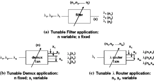
In Fig. 2, the basic holographic device applications, tunable filters, demultiplexers and routers, are illustrated. The design roules for holographic demultiplexers and routers take equations (4) and (5) into account, Martin Minguez and Horche (2005), both of them coming from (3):
/ n 1\
\ND + d)
\ND + d)
/ x 1\ /Ax\
) ND => An « ( — )ND
* AA./ ( (4)
(5)
where, Ax, is the distance between the output fibers, An and Ak are the minimum variation in the hologram period and in the input fiber wavelength to reach the output fibers location, respectively.
In the next section, some guidelines for designing holograms by computer are described.
3 Computer generated holograms (CGH's) design
Taking into account the considerations made in Martin Minguez and Horche (2006), the relationships between the hologram and its Fourier Transform (FT.) function are:
Hologram —»• F.T. —»• Diffraction target Diffraction target —»• F . T '- 1 —»• Hologram
( n „ n2 rij)
An, A , , . . . A:
(a) Tunable Filter application: n variable: x fixed
<ni >n2 nm )
r
xx/x
2>
- XJ[xn)
l x2 X ^ x , )
~H x xi(n2x2)
^ i (nmX m)
(b) Tunable Demux application: n fixed; x, variable
Fig. 2 Basic holographic applications: a tunable filter, b tunable demultiplexer and c tunable I router (c) Tunable X Router application:
nh X;, variable
c = X
2 \ 2
(If ~ A1)
A? (7)
where if is the calculated spot intensity for the diffraction order i; A2 is its defined intensity and A2 is the average (uniform) intensity for the diffraction target spots; t is the process temperature.
There are three steps in a CGH design process:
1. Diffraction Target definition: the target is the diffraction pattern that can be obtained by the SLM. Depending on the use, filter, switch or others, this target is usually an array or a matrix of spots. This is the input for the program.
2. Fourier Transform calculation: the program calculates the inverse Fourier Transform ( F T . )- 1 of the target. The optimization algorithm compares the FT of the hologram with the defined target improving at each calculation time the efficiency. Hologram pixels are flipped between the amplitude values 0, 1 (or phase 0, it) to reduce an error function, (5), specifying the difference between the desired target in the Fourier plane and the reconstruction carried out by the current state of the hologram, improving the efficiency at each calculation. The efficiency, 77, is defined as : 77 = Em orders diffracted light
/total incident light.
3. Finally, the CGH implementation in an optical substrate, like a photographic film or SLM.
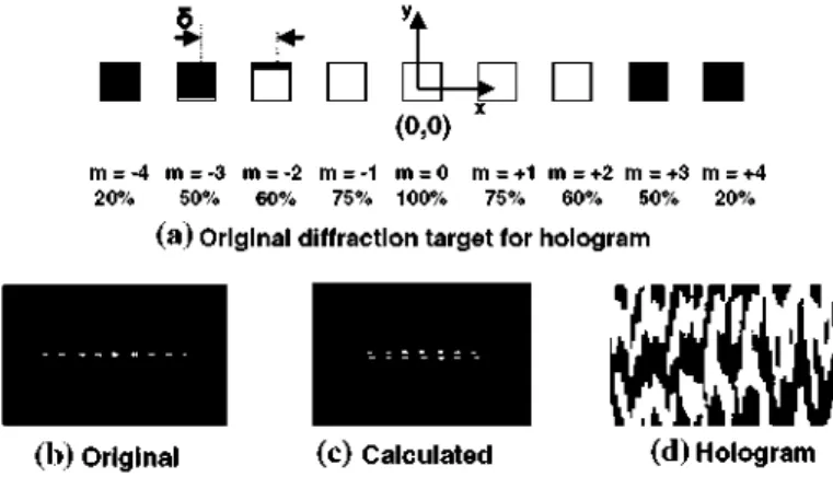
The CGH designed for this work is a black & white bars pattern implemented onto a Spatial Light Modulator, where there are only two possible states: " 1 " for white (total transparency or it phase shift) and "0" for black (total darkness or 0 phase shift). Figure 3 shows the original diffraction target (a), an array of spots with different light intensities (non uniform, like in Fig. 4a), and three consecutive holograms (b, c, d), calculated by the program carrying out the inverse FT according to the algorithm efficiency. A 45% of efficiency is the initial calculation value and closed to 90% efficiency is practically the best result in the optimization process.
(a) Diffraction target
<b)Hoiogram: 11= 45% ef!
(c) Hologram: 11 -7 {)%
(d) Hologram: n.=90%
Fig. 3 Hologram calculation process according to the algorithm efficiency r]: a diffraction target; b, c and d are calculated holograms with r\ = 45, 70 and 90%, respectively
• • B-Q •
(0,0) '
m = -4 m = -3 m = -2 m = -1 m = 0 20% 50% 60% 75% 100%
m = +1 m = +2 m = +3 m = +4 75% 60% 50% 20%
(a) Original diffraction target for hologram
(b) Original (c) Calculated (d) Hologram
Fig. 4 a "Zoom" of the original diffraction target, b original shifted diffraction pattern along the y axis, c calculated diffraction target and d calculated hologram when the original pattern is shifted
diffraction target and efficiency, optimization process parameters...), to modify the direc-tion for the optimizadirec-tion process allowing the algorithm to escape from a local minimum and reaching the correct hologram.
The computer calculations are very sensitive to the geometrical distribution of the original diffraction target. A very light misalignment on it can produce a hologram completely differ-ent of the correct one. This effect is shown in Fig. 4 when the original array of spots (Fig. 4a) is shifted a 30% of spots distance S, (Fig. 4b), along the vertical axis y; the calculated target (Fig. 4c) is an array of spots "duplicated" and "shifted" instead of a singular one.
DWDM
A A (nm)
BW (nm)
l()(nm) N.D( mm)
/(mm)
x(mm)
3>(°) >-max(nm) >-min(nm)
1,510-1
1
1,551 5.04
25.00 12.463
26.51 1,591 1,531
4 Holographic WDM devices description and simulation: basic structures
4.1 Tunable holographic filter
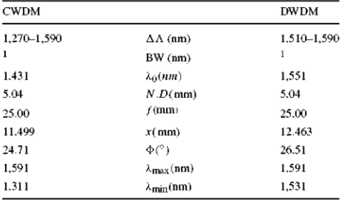
In order to design a tunable holographic filter with a — 3dB pass band width, BW, of 1 nm (125 GHz), for each wavelength channel tuned, we take d = 3.5 /xm for the spatial period of the fixed grating. To use the same device for CWDM/DWDM, a SLM with a value of
N = 720 and D = 7\im for the spatial period, is chosen. The output singlemode fibers used
in our device have a core diameter, <t> of 9\ira. Then, fromMartin Minguez and Horche (2005) expression (5), / must be greater than 23.9 mm. As a practical value we take / = 25 mm.
Table 1 summarizes the filter values for CWDM systems applications where channels are allocated between Xmul = 1,310 nmandXmax = 1,590 nm, with central wavelength ko = 1,431 nm, and for DWDM systems (Xmin = 1, 530nmandXm a x = 1, 590nm, ko = 1,551 nm).
The operation as a tunable CWDM/DWDM filter is obtained by changing the hologram period, n. From the output fibers (Fl to F10), a CWDM tunable filter uses the FA and a DWDM filter uses the F 8 fiber, (see Fig. la).
The simulation of a tunable holographic filter, from a transmission performance point of view, is shown in Fig. 5. This is another novel approach realized in this paper. For each value of the hologram, ni, a tuned wavelength, ki, (i = 1, 2, 3, 4), is obtained. The correspon-dence between the physical blocks of the Fig. la) and the simulated ones of the Fig. 5, is the following:
- SLM and fixed grading assembly: 2nd order optical Bessel filters for tuning the output wavelengths, ki
- lens and SLM holograms: diffraction and selection elements to choose the correct holo-gram, ni
- filter losses: are distributed among the different blocks (Martin Minguez and Horche 2005): diffraction elements, < 5 + 5 < 10 dB and filter losses, < 2 dB
Figure 6 shows a simulation of the wavelength response of the holographic filter. For wave-lengths close to the central, the filter response is very similar to the Gauss filter (5); for wavelengths far from the central, the filter response is similar to the 2nd order Bessel filter (7) with less out band attenuation. Both of them have a lineal phase characteristic, which means, a constant group delay. These simulations are in agreement with experimental mea-surements shown in Parker et al. (1998).
Table 1 Holographic device rwnivr parameters for CWDM/DWDM
filter application , 970-1 590
1
1,431 5.04
25.00
11.499
24.71 1,591
Simulated Holographic Tun i l l I e Filter
mi
HPZ P\is* Oi lerarpr
Ml-
1lambdas: 1 . ! , 3.1
Dptkn * t * n
@ng>ft3rij l>g*rt S( tf *
UEW D*firwd Et -itquwci
B
r^
Holograms: n f ( H A M )• L01 -^—i
Holograph Fl tr Cwirei
te4S*tatirBi!Md Cif radKfi Eternal
Loss: 5 *
A
BOFilH (bmbd! I)
A
BOFttrrjafcta^_
6 0 Filter f U T i * 3)
A
Bessd Opted Filers Loss: 2 *
B1D1-—i
Hcfcgraffce F h*r Cwrtrc*
^ - g - ^5 3:
& k a c * B«r*nt 4/1
bnbi)3 4)
Cifratfen Elemenl L o s s : S *
Fig. 5 Simulation of a tunable Holographic Filter
Opiicjl**™ i w j laiTbdai
Ml!
Optical Sp*ttrjm_1
HfGa uss
HfBESSEL
l/{-j2it.BW).e
-(A-A0)2/2-BW2^o3/[(A - A0r + 3(A.
-4.2 Wavelength division demultiplexer
BW/2< A < kQ + BW/2 (5)
A0) + 3],A < A0- BW/2, X > k0 + BW/2 (6)
We can use this device as a 1 x M demultiplexer, where M is the output fibers number. For this, a fixed value of n is used and the output fibers are located in at different x position. Output fibers (9/125|xm) must be placed in agreement with the diffracted angles <t>, according to input wavelengths and they have to be separated at least Ax = 125[xm.
From (4), we can calculate the Ax taking the value of center to center wavelength channel separation, AA, into account; for CWDM systems Ax = 321[xm -> AA = 40 nm and for DWDM systems Ax = 161[im -> AA = 20nm(*).
In order to design a compatible device with the frequency grid provided in ITU-T G.694.1/G.694.2 Recs. for CWDM/DWDM systems, a 1 x 4 demultiplexer (M = 4) for DWDM with Ax = 161 [im and a 1 x 8 demultiplexer (M = 8) for CWDM with Ax = 321[xm, can be performed.
Table 2 summarizes the fiber position in order to select the wavelengths used in the CWDM/DWDM systems. CWDM system uses F l , F2, F3, F4, F5, F6, F8 and F10 and DWDM uses F7, F8, F9, and F10 output fibers.
(*) In this case, Ak's < 20nm are not feasible due to the physical dimension of the device (i.e. AA = 2nm and Ax = 161[xm -> / , focal distance of the lens, = 25 cm).
Figure 7 shows the simulation of a tunable holographic demultiplexer. The blocks are analogue to the filter simulation, but in this case, the demultiplexed wavelengths, ki, are obtained at different position of the output fibers Fi (i = 1,2,3,4), for the same hologram.
- 3 dB BW: B-C - 1.68«iii (lambda: 1531 ran)
A
1.48(1 1 5 1 ( 1 1.541J 1 5 7 ( 1 1 £ (1
W a v e l e n g t h (m>
1 £2 (1 1 S3 (J 1 5 4 (1
W a v e l e n g t h Cm)
Fig. 6 a Wavelength response of the simulated Holographic Filter ().Q = 1,531 nm); b central wavelength region view
Table 2 Holographic device parameters for demultiplexers/routers application
Output fiber F\ F2 F3 F4 f5 F6 F1 F$ F9 FlO x(\im) 10.535 10.856 11.178 11.499 11.821 12.142 12.303 12.463 12.624 12.785 Demux A. (nm)
n = 180
1,311 1,351 1,391 1,431 1,471 1,511 1,531 1,551 1,571 1,591 A.o = 44 89 135 180 225 270 315 360 1,431 nm Router n value
A.o = 1,551 nm
159
180
201
222
adjacent channels, AB, is >30 dB (worst case for CWDM, where AX = 20nm). The optical spectrum of the Fig. 7 is located at the Fiber 3 output (X3 = l,531nm).
4.3 Wavelength router
Maintaining the output fibers in the same place, as showed in Table 2, if n value (type of hologram) is properly varied, a certain wavelength coming from the input fiber can be routed to any one of the output fibers. As an example, Table 2 highlights the n values for routing
X0 = 1,43 lnm (CWDM) and X0 = 1,551 (DWDM) towards an output fiber; this values
have been calculated from (5), by considering the variation of n according to Ax. For Ax = 161[xm, An was calculated by using (5) resulting An = 21 andfor Ax = 321[xm, An = 45. Therefore, the device is a 1 x 8X router in case of CWDM and 1 x 4 l router for DWDM systems (Crossland et al. 2000).
Slinul.iieil Holoiji.iphic Tumble Deinnltlplexei
1.2.3,4
iiiT.MTrj:
mrtl.-.-fc
B
Optical Spsctrum
Hologram: n
FI > lambda 1 F3 — - » l * r t x * a 3
F2 > lambda 2 F4 > lambda 4
Cortical Atenj L P^w Spun** 1*4 Difraclion BJemem
LOT; • Ui-JB
. V
•• .IMS-- i l . i i i : :.i I )
A
BOjfiltcr<bmbda2)A
BOFterrJvnbd in
A-
? u f i - - - r i l i ' : . i : 4)Bes sel Optical Filter 5 Loss: 2 (£l
JB
FNoer 3 0 p , i™ ' S p": l mFig. 7 Simulation of a tunable Holographic Demultiplexer
1.48|J 151 fJ 1.54(1 1S7p
Wavelength (m)
1.48(1 1 S I | 1 1.54 (J 1.5711
Wavelength (m)
Fig. 8 Wavelength response of the Holographic Demultiplexer, a input wavelengths ().\ = 1, 491, )-2 1,511, A3 = 1, 531, A.4 = 1, 551 nm);bF3 output
Figure 9 shows the simulation of a tunable holographic X router. Its blocks are also ana-logue to the filter and demultiplexer simulations, but in this case, the routed wavelength,
Xi, is addressed to a different output fiber Fi (i = 1, 2, 3, 4), according to the hologram ni
selected, as it can be observed in Fig. 10 for X3 = l,531nm.
5 Holographic WDM devices description: composed structures
S i m u l a t e d H o l o c j i . i p h i c T n n , i M e R o u t e i
T x
Optical Traniiriiflir
I--"-];
Qp1le»t $ p « injm
Holograms: ni (i-1.2,3,4)
aim
H&l*gr»£hio Fil * f Ci'TOftH, 1 BOFilt+f (l»mfrfl» 3^
>M*—-Optical Attenuator
1x4 Scholar t Detraction Elemerrt
Loss: 10 dB
j tambda 3 *= 1531 nm]
A*
A
B Of itier (lambda 3)
- A
21
Bessel Optical Filters Loss : 2 dB
pM^j Fiber 3 °Ptia^i Spectrjm_
Fig. 9 Simulation of a tunable Holographic Wavelength Router
(a)
(b)
<?;
t '
m3 *
o
.
'
o
.
i
I/ I
/
\
/
\ _
14(1
Wavelength <m)
1.4 (J t£|! 1.6 M
Wavelength (m)
Fig. 10 Wavelength response of the Holographic Router ()3 = 1, 531 nm): a input fiber and b F3 output fiber
fixed de/multiplexers based, for example, in Bragg grating filters (Sadot and Boimovich 1998).
In the following, some examples of these configurations are pointed out; in all of them the basic holographic device is a X router l x M working in a wavelength range from 1,270 to 1,610 nm; therefore, in this case, both CWDM/DWDM systems can be addressed.
The generic tunable composed device follows the structure: fixed WDM multiplex + tun-able holographic X router 1 x M + fixed WDM demultiplexer; according to the application, the fixed WDM multiplexer could be removed if a single wavelength is applied to the input. Figure 11 shows an optical tunable ADM/Switch 2 x 2 where two X routers 1 x 2 and two fixed mux 2 x 1 are interconnected. Different output wavelengths combination, in this case four (22), are obtained according to the X router hologram type (nij). This device can work as Optical ADM or Optical Switch according to the application, taking into account that the two outputs are complementary.
a.,
(nH >ni 2 )
^
(n21,n22)
mux 2x1
mux 2x1
a1(n11,n22) a2(n12,n21)
a, +X2(n12,n21) 0(n12,n22)
T*
nM = bars number in a binary black&white hologram
Tunable holographic device
a2(n11,n22)
Mni 2 >n2 i ) 0(n12,n21)
1 +^-2 (^12»^22)
I | Fixed optical multiplexer
Fig. 11 Optical tunable ADM/Switch 2 x 2
wavelengths. To perform a complete ADM/Switch, a 1 x 2 demultiplexer is added to the former device; in this way any combination of the input wavelengths is addressed to the output, in total 8 (23). The drawback of this configuration is the addition of the demultiplexer insertion losses to the final transmission path.
Other structure is a Multiplexer/Switch 4 x 2 , composed by 4 k routers 1 x 2 and 2 mul-tiplexers 4 x 1 , where also the 2 outputs are complementary; 16 different combinations of
ki (i = 1, 2, 3, 4) are possible at each output. This device performs a twofold function, as a
multiplexer and as a switch, by reducing the number of fibers at the output.
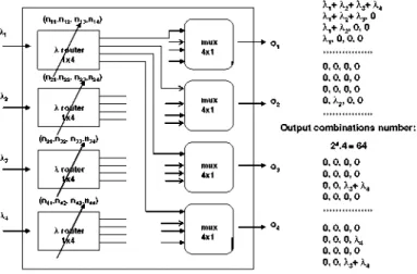
Finally, the device of the Fig. 12 is a full Switch 4 x 4 matrix with 64 output combinations, at each output, according to the holograms stored on the k routers. One way to serialize the four k inputs is to place a demultiplexer ( 1 x 4 ) before the k routers.
All these tunable holographic devices have different applications in Metro and Access networks as it is described in the following sections.
6 Performance parameters
In the following, some performance parameters are described for this type of devices; these parameters are the reference to evaluate the adaptation of the devices for networking applica-tions. In Ma and Kuo (2003) there is a complete comparison of several switching technologies according to different criteria:
insertion loss: composed of the k router and de/multiplexer losses. An optimizated value
Fig. 12 Full Switch 4 x 4 Matrix
- switching time: due to the SLM optical switching time; it was estimated to be 250—300 [is, as the sum of the electric storage and FLC material response times, Horche and Gonzalez (2001).
- crosstalk: in the holographic devices, due to the position of the fibers, the crosstalk result-ing from high-order diffraction beams (m = ± 2 , ± 3 , .) is outside of the location of the output array fibers (A<t> < 4°). Crosstalk less than —40 dB is a typical value (Holmes and Crossland 1994).
- polarization dependency: one of the advantages of using this technology, FLC, is its insensitivity to the light polarization for a certain range of wavelengths, allowing the increment of the transmission length.
Advantages
- multifunctional device: application as a tunable filter, demultiplexer, router, OADM or optical switch, with tunable outputs depending on the input wavelengths and holograms. - bit rate and signal protocol independency: as an all-optical switch, not electro-optical
conversion is carried out, therefore, a non electrical signal parameters dependency is reached.
- switching time: as it is few hundreds of [is, the OADM/OS application in path restoration is appropriated from the service loss point of view.
- wavelength depending switching: this feature is very useful for the use of these devices as OADMs due to the additional filtering provided.
- insensitivity to the light polarization: not dynamic dispersion compensation is required to avoid transmission losses due to this characteristic.
Constraints
- losses: in composed devices it is the sum of the holographic device and the mux/ demux losses; it is necessary to optimize the design of the device to reduce them (Ahderom et al. 2002), taking into account that the losses due to the holographic part are fixed, independent of the output number.
All optical switching [X conversion + X routing)
Control
Control
Tunable laser
^A
VC W 1
I
J~
l w , ACW1
wi ' • I ^cw2 HOLOGRAPHIC "" \
SOA XCW3 X ROUTER —
Xt (modulated) X° 4 I '
gain: 10 dB losses: 10 dB
^CW3
CW4
Insertion losses: 0 dB
Fig. 13 Device composed by an optical I converter and a holographic I router
lineal operation using the Cross Gain Modulation (XGM) method. An incident wavelength,
Xi, modulated by a digital signal is combined with the wavelength Xcwj generated by a
tunable laser (CW) into the SOA. At the amplifier output, according to different CWj wave-lengths, Xcwj signals are obtained modulated with the digital signal from the incident Xi wavelength. These Xcwj signals are also amplified and inverted.
The holographic wavelength router, depending on the input signal, Xcwj, and the gener-ated hologram (nij) stored in the SLM, addresses this signal to the assigned output. As it has been commented, this technology has the drawback of the high insertion losses (less than 10 dB, using an optimized device). In order to solve this problem, by combining a SOA with the holographic router, this insertion loss is compensated with the amplifier gain in the saturation zone of operation. A parameter to control in the SOA operation, is related with the amplified spontaneous emission (ASE) because of the impact on the signal deformation.
Figure 14 shows the simulation of this device, composed of three different blocks: a CW tunable laser, a wavelength conversion semiconductor optical amplifier and a wavelength holographic router.
In Fig. 15, the response of the Wavelength Conversion and Routing Holographic Device (WCR-HD) is represented for a 2.5 Gb/s input signal, Xj„ = 1,540 nm, that is converted to an output signal, Xout = 1,520 nm, where the losses of the holographic router are compensated by the gain of the SOA.
- holograms generation and operation: for the operation of these devices it is necessary to generate holograms, usually with a computer, CGH (Computer Generated Holograms) (Dames et al. 1991), and to configure with them the SLM. To perform the switching operation a closed control between the holographic component (SLM) and the computer is needed to assign the correspondent hologram from a local database. This performance is represented in Fig. 16, where a switching control acts over the PC-SLMs interface.
7 Application in Metro and Access optical networks
Figure 17 shows a typical Access and Metro network configuration.
Simulated CW tunable loser
y
C W L i s . r
• M
•-CW laser J
to-
Ideal V Selee Nx1Tx
Q1D1
S*«oh-Tuning Control
-3>
Opr:: 3 T r a n s m i t t «W a v e l e n g t h conversion
£>
_.. W D M M J K 2 K | SOAin. &aby?ted regkm Gaussian Critical Fih>Gain = £0 dB
M
Optical Time Domain Usualizer„G3
Optical Tune Domain - Is ualiz*r_ I
W a v e l e n g t h Routing
DID:
-HD Cortrol (Hologram)
A
Bessel Optical Filter Ideal Switch 1x4
Simulated Holographic Switch
Z3
SB
Rx
Optica* Spectrum Analyzer Optical S p e c t i u n A i a l y z e r _ 2
Fig. 14 Wavelength Conversion and Routing Holographic Device (WCR-HD) simulation
cases, depending on the size of the city, several Metro networks are interconnected by optical switches with a "gateway Metro network" to communicate with the long haul network (1 Gbit/s - 4 0 Gbit/s).
Three different Access networks are drawn in the figure:
- Point to Point (P-P): with a dedicated link between the OLT (Optical Line Termination) placed at the CO (Central Office) and the ONT (Optical Network Termination) at the customer premises. Typical bit rates of 622 Mb/s (down) and 155 Mb/s (up) are used in this network.
- FTTO: Fiber to the Office Passive Optical Network, with an intermediate branching point or Remote Node (RN), where splitters, mux/demux, AWGs,..., are placed for addressing the services to the correspondent BONT (Business ONT). Usually, a LAN (Local Area Network) is connected to the BONT to distribute the services among the different user's terminals, acting as a hub. Typical bit rates of 2.5/1 Gb/s (down) and 1,000/622 Mb/s (up) are used in this networks.
- FTTH: Fiber to the Home, similar to the former network, but in this case the RONT (Residential ONT) is less complex than the BONT. Triple Play services (voice, video, data) are provided by these networks where distribution services like TV, BB Internet, use a great quantity of bandwidth. Bit rates of 1 Gb/s- 622 Mb/s (down) and 622-150 Mb/s (up) are currently used in this application.
7.1 Tunable holographic devices application in Metro networks
(aj Signal Power
o,
g
ll
• •
-NRZ Input |
^ (
-"i h -"i
I.
,
-
( •>h
3e-0C9 6e-009 9e-009 1.2e-008 Time (B)
(b) 0 Factor
1
Q Factor •oo
IMRZ Output |
3
3
"
1
L
n
\_
n fi
. Ju
| r
1 1
"
—
ih
,
II
0 3e-009 5e-009 9e-009 1.2e-003 Time Is)
<=t
CT
S-/
\
J^y
\ l0.2 0.4 0 6 0 8 Time* (bit p e r i o d )
P?
o
/
c
(c) Eye Diagram
/
(
/ \
0 3 0 & 0 9 1.2 T i m e (bit p e r i o d )
| Mm. BER |
Fig. 15 WCR-HD response for a 2.5 Gbit/s input signal: a ).jn = 1,540 nm, with wavelength conversion, X0ut = 1,520 nm, and losses compensation, b Q factor ss 100 and c BER ss 0
(Hi assigment to the SLMj) according to nN
PC-SLMs Interface
f
Switching controlHolograms (H) stored in the PC
Holographic device
Access and Metro Networks configuration
Primary path Spare path
LONG HAUL network
BONT: Business Optical Network Ternination RONT: Residential Optical Network Ternination RN: Remote Node ,, OLT: Optical Line Termination
FTTH: Fiber to the Home FTTO: Fiber to the Office P-P: Point to Point
Access Networks
Fig. 17 Generic Access and Metro networks
Metro Networks application
location for tunable holographic devices use
LONG HAUL network
A,,+ ^2, 0 , 0
%,, 0 , 0 , 0
Fig. 18 Protection path 1 + 1 and Switching node applications in Metro networks
Biridectional CWDM Multi-PON (Mux-Filter; 1+1 OLT-RN)
Tx,s Array
}'i
• •
•
'A
(*) X dependent services
Fig. 19 Example of a FTTO Access Network configuration
this way the secondary ring (A.2) becomes active. As the switching time is about few hundreds of [is, a quick path restoration could be reached.
In the second one, an Optical Switch 2 x 2 (or 4 x 4) can be used to interconnect two Metro rings networks for exchanging its wavelengths or to route any combination of the Aj (1 = 1, 2 . . . 3, 4) to the nodes of the rings; in this way both networks have access to the long-haul network and a full interconnectivity between them is obtained.
7.2 Application in Access networks
Figure 19 illustrates a generic Multi-PON FTTO network using CWDM (Coarse Wavelength Division Multiplexing) technology where 4 PONs are addressed. At the Remote Node (RN), between the OLT and the BONTs, passive elements, like splitters, combiners, multiplex-ers,., are placed for interconnections with the remote network terminations, ONTs (Martin Minguez and Horche 2007b).
In each PON, an ONThas access to all wavelengths in the down direction (Ai, A2, A3, A4), selecting one of them by a tunable filter; with this configuration, instead of an optical demul-tiplexer, a splitter is placed in the RN. In the upstream direction each PON transmits in the assigned wavelength (A.5, A.6, A7, As) and by a multiplexer in the RN all of them are placed in the same fiber.
A bidirectional fiber between the RN and the ONTs can be used to save cost fiber instal-lation; from the OLT to the RN two different fibers (down and up) are installed for reliability reasons (all Multi-PON traffic is going through this path).
The technical characteristics of this network are shown in Table 3 and they are in agreement with ITU G. 983.x Recommendations.
Table 3 FTTO network technical characteristics (according to ITU Rec. 983.x)
Bit rate: Down: 2.4 Gb/s Up: 1.2 Gb/s
Power budget (3 dB of system margin): Down: 20+3= 23 dB
Up: 20+3= 23 dB Max. Distance:
OLT-Branching Point: 10 Km Branching Point- ONTs: 15 Km Wavelength allocation (CWDM):
Down: A4 = 1,471 nm; k2 = 1,491 nm; k3 = 1,511 nm; k4 = 1,531 nm
Up: k$ = 1,551 nm; A.g = 1,571 nm; kj = 1,591 nm; kg = 1,611 nm
Tx mean channel output power: OLT: 0 dBm
ONT: -3 dBm
Rx mean channel input power: OLT: - 2 3 dBm
ONT: - 2 0 dBm
Max. chromatic dispersion:
Down: 1,600 ps/nm Up: 2,000 ps/nm
BONT Tunable optical filter
13
RN
Coupler 2xn
<-^ 1 (nn ' " 2 2 )
J.2 (n1 2,n2 1)
k2 ( n „ ,n22) i-1 (n 12 ,n 2 1)
( i i / n i 2 ) OADM2X2
(nyvn22)
1,
l2
Optical path protection (between RN and OLT) Fig. 20 BON Tunable optical filter and Protection OLT-RN path 1 + 1 applications
wavelength where assigned services for the subscribers are provided; this type of feature could be useful when the BONT, due to the complexity of the LAN connected to, acts as a hub managing the subscriber premises network and the services assignment.
In the other application, an OADM 2 x 2 is used to protect the optical path between the OLT (Optical Line Termination) and the RN (Remote Node or branching point); in case of a fiber failure, the services can be re-routed to the spare path by switching the device from the primary working path to the spare one.
WDMNlkfel. • • > • Fiber i
JWH:
Optical Spwtmm tambde 1, lambda 2, tambda 3, lambda 4 (rosin operetten: ml 1 h ntf1, n 3 l , n41)
lambda 1, lambda 2, lambda 3, lambda 4 (spare operation: n l 2 , n22, fi32, n42)
• M
Optieil Sp«tntm_1
(b)
!
i
-• '
r-
•r-f * •r-f •r-f i «t«>»1-2tj-4(ni;
|
1111 Ml !
1
IIIJ
,n?2/ti2 ntf.
1.3U 1.4y t Sp 16(1 I T p 1By Wavelength f m )
M r
f
1
T* D
1 • s
;-;.
fieri IMMa1o2«3 [ m i , n a , r o i , M I )
1
/
1
/ I
13p 1 4y 1.5M 1 &U 1?P 1 J3jj
• , - M V I . - i
Fig. 21 a Simulated Holographic Multiplexer/Switch 4 x 2 structure, b and c operation results according to the chosen hologram (nij)
In Fig. 22a, the eye diagram at ONT side after a total distance (OLT_RN)+(RN_ONT) of 10+15 = 25 Km is presented for a BER = 1.10-11 (Fig. 22 b). Values from Table 3 have been chosen regarding the bit-rate, 2.4 Gbit/s and power budget, 20 dB. The operation wavelength is X = 1,511 nm.
8 Comparison with other currently used technologies
(a) Eye Diagram (b) Bit Error Rate (BER)
Fig. 22 Simulated Access Network performance with values of Table 3: a Eye diagram and b BER at the ONT side
Table 4 Wavelength selective routing technologies for ROADMs
Technology Principle of operation Advantages Drawbacks
Holographic SLMs with liquid crystal components
Micro-electrome-chanical systems (MEMS) '
Control of light diffraction by holograms
Physical displacement of light using mirrored MEMS surfaces
Non complex implementation
Scalable over a wide range of port sizes
Optical performance degrades for high port counts due to losses and cross-talk Not economical for
low port counts due to the complex implementation
requires different sizes and configurations of them, Homa and Bala (2008). At present, there are requirements with port counts ranging from l x l through 1 x N, (N> 10) with equal-ization of the input wavelengths power level. Table 4 provides a high-level summary of two of the main technologies currently being used for ROADMs. In the case of low port counts 1 x 1 , 2 x 1 , and 4 x 1 , holographic liquid crystal-based design for economy and ease of manufacture can be used. For high port counts the use of a combination of MEMS (Micro-Electro-Mechanical Systems) for wavelength switching and liquid crystal for equal-ization is a current option.
In Martin-Minguez et al. (2010) the design of equalized holographic ROADM devices for applications in CWDM optical networks have been developed by using a mixed hologram corresponding to the combination of several input wavelengths. The tuning of a broad range of wavelengths is obtained allowing full routing of several channels from the input fiber to the outputs.
To reduce the total insertion losses of the holographic device and to increment the input power range for equalization, a SOA has been added. The device designed in Martin-Minguez et al. (2010) is able, with the same physical structure, to cover the complete CWDM band, 1,271-1,611 nm, by using groups of 4 input wavelengths (separated 20 nm), as it is recom-mended in ITU G. 695.
9 Conclusions
Tunable holographic WDM devices for applications in optical networks have been studied. Based on the same holographic structure, designs of both basic and composed devices have been provided. Simulations of them, from the optical transmission point of view, have been done for applications like filters, routers or optical switches; these simulations take into account the adaptation of holographic optical components characteristics (SLM, diffraction grating, lens) to transmission component parameters (filter, attenuator, splitter) in order to use a commercial software for optical communication systems applications. In addition, short guidelines for Computer Holograms Design are provided to address some issues related to the operation of these holographic devices.
Performance parameters, like losses, switching time, crosstalk and polarization insensitiv-ity have been analyzed. These parameters have very competitive characteristics with respect to other switching technologies; in order to reduce the insertion losses, a device optimiza-tion design has been done. Wavelength conversion and routing applicaoptimiza-tion using a SOA to compensate its losses, has been described.
Moreover, the use of tunable holographic WDM devices in Metro and Access networks has been analyzed. Applications in Metro networks like path protection between nodes or a switch matrix for ring networks interconnection, have been commented. Other applications in Access networks, like OLT-RN path protection or the use of tunable filters in the BONT to select wavelengths according to the type of services provided, show the versatility of these devices in this type of networks.
Acknowledgments The authors gratefully acknowledge the support of the MICINN (Spain) through project TEC2010-18540 (ROADtoPON).
References
Ahderom, S., Raisi, M., et al.: Applications of liquid crystal spatial light modulators in optical communica-tions. High Speed Networks and Multimedia Communications, 5th International Conference on, 3-5, pp. 239-242, July (2002)
Crossland, W.A. et al.: Holographic optical switching: the ROSES demostrator. J. Lightwave. Tech. 18(12), 1845-1853 (2000)
Dames, M., Dowling, R. et al.: Efficient optical elements to generate intensity weighted spot arrays: design and fabrication. Appl. Opt. 30, 2685-2691 (1991)
Holmes, M.J., Crossland, W.A.: Optimization of WDM demultiplexers. IEE-Colloquium-on- 'Transpar-ent-Optical-Networks:-Applications,-Architectures-and-Technology'-Digest No. 1994/103. 1994: 8/1-7 1994
Homa, J., Bala, K.: ROADM Architectures and Their Enabling WSS Technology. IEEE Communications Magazine, pp 150-153, July (2008)
Tunable holographic components in WDM optical networks 67
Kashnow, R.A., Bigelow, J.E.: Diffraction from a liquid crystal phase grating. Appl. Opt. 12(10), 2303– 2304 (1973)
Ma, X., Kuo, G.S.: Optical switching technology comparison: optical MEMs vs. other technologies. IEEE Optical Communications S16–S23, Nov (2003)
Martín Minguez, A.: Contribución al estudio y optimización de dispositivos basados en holografía dinámica para su uso en redes ópticas pasivas multiplexadas en longitud de onda, WDM-PON. Tesis Doctoral, Universidad Politécnica de Madrid (UPM), http://oa.upm.es/1781/, Nov (2007)
Martín Minguez, A., Horche, P.R.: Dynamic holographic wavelength filtering for CWDM applications. SPIE’05, Optics & Photonics, paper 5907–1922, San Diego, Aug (2005)
Martín Minguez, A., Horche, P. R.: Tunable WDM Holographic Devices: Aplication in Reconfigurable Access and Metro Networks. Procc. IET 2nd International Conference on Access Technologies, Cambridge, UK, Jun (2006)
Martín Minguez, A., Horche, P.R.: A multipurpose WDM holographic device for filtering, wavelength multi-plexing and routing applications. Phot. Netw. Commun. J. 13(3), 313–322 (2007a)
Martín Minguez, A., Horche, P.R.: Application of WDM Holographic Devices in Access and Metro Net-works. Optical and Quantum Electronics Journal 39(2), 131–146 (2007b)
Martín-Minguez, A., del Rio, C., Horche, P. R.: Design of Equalized Holographic ROADMs (Reconfigura-ble Optical Add-Drop Multiplexers). III International Workshop on Liquid Crystals for Photonics, LCP 2010, Elche 8–10 Sept (2010)
Martín Minguez, A., Horche, P.R.: Design of a device with wavelength multiplexing and routing functions using dynamic holography on SLMs. Opt. Commun. J. 263(2), 166–170 (2006)
Parker, M.C., Cohen, A.D., Mears, R.J.: Programmable Holographic Elements for WDM, IEE-Colloquium-on-Optoelectronic-Integration-and-Switching-Ref.-No.1997/372. 1997: 10/1-6 IEE, (1997)
Parker, M.C., et al.: Dynamic digital holographic wavelength filtering. J. Lightwave. Tech. 16(7), 1259– 1270 (1998)
Riza, A., Yuan, S.: Reconfigurable wavelength Add-Drop filtering based on a Banyan network topology and Ferroelectric Liquid Crystal fiber optics switches. J. of Lightwave Technology 17(9), 1575–1584 (1999) Sadot, D., Boimovich, E.: Tunable optical filters for dense WDM networks. IEEE Communications Magazine,
pp. 50–55, Dec (1998)
Tebben, D., Nolan, D. et al.: Two-Fiber Optical Shared Protection Ring with Bi-directional 4 × 4 Optical Switch Fabrics LEOS 2001. The 14th Annual Meeting of the IEEE, vol. 1, pp. 228–229 (2001)