Influence of the rheological behaviour of the lubricant on the
appearance of pitting in elastohydrodynamic regime
J. ECHAVARRI OTERO, E. DE LA GUERRA OCHOA, E. CHACÓN TANARRO, P. LAFONT MORGADO, A. DÍAZ LANTADA, J. M. MUNOZ-GUIJOSA and J. L. MUÑOZ SANZ
ABSTRACT This paper analyses the influence of lubricant behaviour on the appearance of pit-ting. It attempts to study the effect of viscosity-pressure relation, compressibility, film thickness-roughness relation and friction coefficient on pitting failure of the contacting elements. T o explain these effects, we first deal with the influence of the oil on the lubrica-tion of the contact using elastohydrodynamic theory and secondly two multiaxial fatigue criteria are used, Crossland criterion and Dang Van criterion, to evaluate the influence of the rheology on the appearance of pitting. Finally, different applications are presented together with a discussion on the results obtained.
Keywords high-cycle fatigue; lubrication; multiaxial fatigue criterion; rolling contact fatigue (RCF); surface roughness.
NOMENCLATURE a = half-width of the contact area (m)
b = half-width of the contact area for triangular distribution (m) C\, Cj, C3 = constants in the Hoglund equation for density (Pa)
Di, D2 = constants in Dowson-Higginson equation for density ( P a- 1)
E = Reduced Young's modulus (Pa): ^ = j K1^ ) + ( ^ ) ]
G = shear modulus of the lubricant (Pa) h = film thickness (m)
h0 = minimum separation of the contacting surfaces in the case of rigid body approach (m)
J2 = second invariant of stress tensors (Pa2)
Jla = amplitude of the second invariant of stress tensors (Pa2)
K = isotropic hardening parameter (Pa) m = safety coefficient of Melan's theorem
n = Carreau's exponent p = pressure (Pa)
ph = hydrostatic pressure (Pa)
/>i>max = maximum hydrostatic pressure in a cycle (Pa)
pk = peak pressure for triangular distribution (Pa) pD = Hertz pressure (Pa)
Rx = contact radius in the direction x (m): g = ^—h j -R(x,t) = contact roughness (m)
r, n, T2 = geometric coordinates (m)
T = temperature (°C) t = time (s)
um = average surface velocity (m/s) x = direction of motion (m) z = normal direction (m)
a = viscosity-pressure coefficient ( P a- 1)
aD V = dimensionless constant of Dang Van criterion
¿9DV = constant of Dang Van criterion (Pa)
y = shear rate (s_ 1)
A T0ii = rise in lubricant temperature in the contact
Aw = sliding velocity (m/s)
5 = sign + 1 or — 1 in Hóglund's equation for density i] = viscosity (Pa-s)
r¡¡s = low shear viscosity (Pa-s)
rjiso = low shear viscosity at ambient pressure (Pa-s) 6,61, 62 = angular coordinates (rad)
K = dimensionless constant of the Crossland criterion X = constant of the Crossland criterion (Pa)
¡j, = friction coefficient v = Poisson's ratio p = density (kg/m3)
po = density at ambient pressure (kg/m ) £ = mesoscopic stress tensor (Pa) a = macroscopic stress tensor (Pa)
Of = fatigue limit under pure alternative bending (Pa) CTYM = Von Mises equivalent stress (Pa)
a* •• yield stress (Pa) T = shear stress (Pa)
%k = peak shear stress for triangular distribution (Pa) J H , = maximum shear stress amplitude of stress tensors (Pa)
To = maximum octahedral shear stress (Pa)
tw = fatigue limit under pure alternative torsion (Pa) U40 = kinematic viscosity at 40 °C (m2/s)
\\r = mesoscopic residual stress tensor (Pa)
I N T R O D U C T I O N
Surface fatigue, like all fatigue phenomena, is due to the application of cyclical loads. Its appearance depends on the pressures and shear stresses reached in the contacts between mechanical elements subjected to rolling and sliding.1 T h e main consequence of surface fatigue is the
appearance of different size pits on the surface depending on the scope of the damage (spalling, pitting or micropit-ting). These pits cause material loss and induce vibrations and overloads, which result in the element finally failing. This type of failure is typical of bearings, gears,2'3 the
wheel-rail contact of trains4 and even artificial
prosthe-ses.5
Introducing lubricant into bearing or gear contacts may improve resistance to fatigue by obtaining fully flooded
film and a decrease in friction. In order to test the effec-tiveness of lubricants in improving fatigue there is a wide range of normalized tests.
T h e study of the influence of lubrication will be con-ducted by solving the equations involved in elastohydro-dynamic lubrication (EHL)8: the Reynolds equation, the
rheological behaviour and the elastic deformation equa-tion in order to find the pressures and shear stresses in the contact. Once these have been calculated, the stresses inside the material are calculated so that the fatigue crite-rion can be finally applied.
For the study of cases of complex fatigue, such as the case we are dealing with, in recent years numerous multiaxial fatigue criteria have emerged.9 In this paper, Dang Van
rheology and the different parameters with influence on surface fatigue.
L U B R I C A T I O N A N D R H E O L O G I C A L M O D E L S
It is commonly accepted that under E H L line contacts the distribution of film thickness1 0 - 1 2 and pressure13 behave
approximately in accordance with the Reynolds equation expressed as Eq. (1).
3 /ph3 dp dx \ 12r¡ dx
Hph) , Hph)
Urn, „ "T
dx dt (1)
For this study the rise in contact temperature is consid-ered as negligible and thus isothermal regime is assumed.
By applying the linear elastic theory to two semi-infinite, homogeneous and isotropic contacting bodies, the fol-lowing expression is obtained for the lubricated film thickness.
h (x, t) ho + ^s~ + R(x, t)
2 r+oo
—— / ln(r — x') p(x')dx'.
Tth J_00 (2)
T o numerically solve these equations, the Full Multi-Grid techniques described by Venner and Lubrecht1 4
have been applied to obtain the pressure distribution and film thickness. T h e shear stress (r) can be approached using the expression shown in Eq. (3).15
Aw
x{x) = r]{x)y{x) « i](x)——. (3) h(x)
Viscosity models
For E H L the lubricant behaviour moves away from the Newtonian model. T h e Carreau model, shown in Eq. (4), has been used to represent the behaviour of the lubricant, where the low-shear viscosity is represented ac-cording to the Barus law.17
T](p,T,y) = T]is(p,T) 1 + nisip, T)
= riUT)ea^P 1 + G
'%o(v^y
G
(4)
Density models (Compressibility)
Diverse experimental models have been used for the vari-ation in density with pressure of different lubricants, such as the Hoglund1 8 and the Dowson-Higginson1 9 models
shown in Eqs (5) and (6), respectively, where coefficients
C\, Cj, C-}, Di, Dj and 5, are adjusted to experimental data.
PÍP) Po
PÍP) Po
i + t - W -
1
^
1 + Dip l + D2p'
(5)
(6)
P R E D I C T I N G THE A P P E A R A N C E OF S U R F A C E F A T I G U E
Once the pressure and the shear stress in the contact are known, the macroscopic stresses inside the material can then be calculated, the material being taken as a semi-infinite elastic solid bounded by a plane surface. Due to this idealization of the solid, it can be considered to have a state of plane strain.20
Figure 1 represents an outline of the solid, axes and triangular distribution of pressure and shear stress.
T o solve the stress field induced by whatever distribution of p(x) and r(x), the principle of superposition is used. T h a t is, the original distributions are divided into a series of equivalent triangular distributions (pkix) and T¿(X)),21
shown in Fig. 1, because these have an analytical solution for the stress field, Eq. (7).
pkix) = / > * ( !
T (x) = Xk 1
1*1
b
\x\ b
\x\ < b
, \x\ < b.
(7)
T h e solution to the stress field resulting from the trian-gular distribution (pressure and shear stress) is given by the following expressions21:
T* = Ü Í {(* - b)9l + (x + b)92 - 29x + 2zln {^f)\
-Ck
2xlnp^)+2Hn
-3z(6>i+6>2-26>)pk
{(x -b)0i+(x + b)e2- 29x)
XkZ
lib {01 + 02 - 29}
(8)
v(^
+ 0
pkz
+ O2-20}+^-\(x-b)
nb I
+ (x + b)92 -2ex + 2z\n(p^p\\,
Oi
where the geometric variables reflected in Fig. 1 are as follows:
r\ = (x - b)2 + z2
r2 = (x + b)2 + z2
r2 = x2 + z2
tan(6>i):
tan(<92):
x — b z x + b
(9)
tan(<9) = - . x
By applying the principle of superposition to each point A(x,z).
k=\ k=\ k=\
N
/ ,
'•xz-(10)
N o w that the macroscopic stresses are known, the meso-scopic stresses or grain level stresses can be calculated, as this is where the cracks first appear. T h e mesoscopic stresses ( £ ) are related to the previously calculated macro-scopic stresses (a), using the mesomacro-scopic residual stress tensor (r/s).2'22
Y
J= ff + ^-
(11)In order to find the mesoscopic residual stresses, Melan's theorem is used, Eq. (12), which proposes an elastic shakedown-based method,22 where the function /
rep-resents the yield criteria or yield surface.
f{ma (x, t)+\¡r (x)) - K2 < 0. (12)
Figure 2 shows a series of stress-strain cycles where the material's elastic limit is exceeded. W h e n this happens, the material undergoes a hardening that is both isotropic and kinematic.23 T h a t is, an increase and a displacement
in the yield surface of the material are produced, which, after a number of cycles, leads to a stabilized pure elastic cycle.
Following the Von Mises criterion, the yield surface (f) is defined by Eq. (13), which represents a six-dimension hypersphere.
-72 - K2 0
Sl+S
2y+*1
2 +s +s +s ~ xy ~ J xz ~ J y
K2 = 0.
(13)
Therefore, the problem can be solved by calculating the radius (K) and the centre (-x/r) of a hypersphere that con-tains all the points of the time history of the macroscopic elastic stresses. Mathematically, this is expressed as an optimization problem for the calculation of the hyper-sphere of least radius containing the time history.24
J
<w
n
:
1»
% 1 I
><7
Tt' Tt"
j Stabilized
/ pim-'eliiHtk
f cycle
1 /? ft C
c c- C"~
j %
i
J Yield Surface <i|
In order to check the severity of the contact during the load cycle, from a fatigue point of view, the Crossland and Dang Van multiaxial fatigue criteria are used.
T h e Dang Van criterion
This criterion has been widely used in the literature to predict life to surface fatigue2'4'25 and sets in Eq. (14) to
find out when the beginning of cracks is not produced.
(t) + aDVpb (t) < PDV, (14)
where the expression for rmaXi, and p¡, are contained in
Eq. (15).
^max,# \p) '•
su(t)-sia(t) 2
ph(t) = - (£*(£) + £j,(i) + Ez(i))
(Ei(í) + E2(í) + E3(í))
(15)
where s\¿„ are the major and minor principal stresses of the alternative part of the deviatoric mesoscopic stress tensor.
Parameters C«DV and /8rjv a r e material constants that are
calculated from pure torsion (r w) and pure bending (ay) fatigue tests for a determined number of cycles.25
PDV = *w
a o v = 3 tw 1
af 2
(16)
T h e Crossland criterion
T h e Crossland criterion is based on the second invariant of stresses and sets the following relation to avoid the appearance of fatigue.
\Zjl,a (*) + Kpb,max < A.. (17)
As in the previous example, k and K are material constants and are calculated likewise.26
Of
k =
%w-(18)
By re-writing both criteria and particularizing for the most unfavourable load cycle conditions, the following is given:
Dang Van -> fieq = max(rmaXííl (t) + aDVph (t)) < fiDV
Crossland -> keq = max (y/J2,a (t) + Kpb,max) < k. (19)
As can be seen in Eqs (16) and (18), ¿SDV and k are
equal to fatigue limit under pure alternative torsion (r w)-Therefore, if the criteria were completely equivalent they should result in the same values, that is keq = f3eq. This means that the contact severity can be measured by us-ing just one sus-ingle parameter: keq or fieq. T h e higher the severity, the more the contact will be subjected to fatigue, and the closer it will be to failure conditions.
In order to apply multiaxial fatigue criteria, macroscopic and mesoscopic stress field can be calculated using Eqs (8), (11) and (13). For this purpose a previous step is to find the pressure and shear stress distributions by solving the E H L equations shown in Eqs (1) to (3). In this way, the effect of the rheology of the lubricant on the appearance of pitting can be explained and predicted.
R E S U L T S A N D D I S C U S S I O N
In order to study the effect of viscosity-pressure coeffi-cient (a), compressibility, friction coefficoeffi-cient (/x) and film thickness (h) three different oils were chosen: LVI260, 5P4E and P A 0 6 . LVI260 is a mixture of different bases with high naphthenic content,27 5P4E is a mixture of
iso-mers of a five-ring polyphenyl ether used for turbines28
and P A 0 6 is a low-viscosity polyalphaolefin used for gears. T h e most suitable density model was taken for each lubricant, whose properties are shown in Tables 1 and 2. All the data were measured at constant temperature (T = 40 °C).
Table 2 includes the base type and the kinematic viscos-ity, which means piezoviscosity can be predicted for other temperatures.32
T h e operating conditions are such that they guarantee E H L lubrication regime for the different oils, bearing in mind their different properties. T h e input conditions selected and the corresponding calculations of friction coefficient, film thickness and shear rate are shown in Table 3.
T o verify the isothermal hypothesis a rough estimation is made of the rise in temperature of the lubricant in the contact, using an analytical method3 3 based on expressions
for line contacts: Hamrock's2 8 formula for central film
thickness (hc) and thermal considerations.34 T h e rise in
lubricant temperature in the contact (AT0¡i) is negligible,
as can be seen in Table 3.
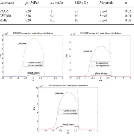
T h e highest values of the viscosity-pressure coefficient produce an increase in the pressure peaks of the E H L distribution and an increase in film thickness.15 On the
other hand, the compressibility reduces the size of the peak and causes a decrease in the central film thickness, while the minimum thickness hardly varies.18 Figure 3
Table 1 Density model constants
Lubricant
PAO 618
Ci(Pa)
1
Lubricant
PAO 630
LVT26028-31
5P4E28
C2(Pa)
24.50
C3(Pa)
0
Base type a(GPa ) i;iso(mPa-s) U40 (mm /s)
Polyalphaolefin (synthetic) 11.50 25 30.24 Naphthenic mineral oil 30.17 428 460.71 Ether (synthetic) 35 340 287.16
po(kg/m3)
830
Lubricant
LVI26019.28.29
5P4£l8,19,28,29
Table 2 Viscosity parameter
D ^ G P a -1)
0.64 0.60
values
D2(GPa-1)
2.89 1.70 po(kg/W) 929 1184 G (MPa) 0.53 0.34 0.68 1.59 5.60 4
Table 3 Operating conditions
Lubricant PAO6 LVI260 5P4E poQ 828 828 828
um (m/s)
2 0.1 0.1 SRR (%) 25 10 10 Materials Steel Steel Steel
hc (nm)
0.02 0.04 0.08 184 267 245
Hs-1)
2.7E6 3.7E4 4.1E4
AToil (°C)
3.4 0.4 0.6 e 7
--3 ¡ .,.'
- i - ,
PAOS P i s w j e arc] títéM litest. ditiLytic 'i
/ >.
pnnut
/ \
/
¿ o i r p m i l *
•
|IK4|IWWH'W
shwrdma
-1 -OS 0 Olí 1 1 ! 1
, ,,3 LvueaPrMiiMtmtiiui<ti«««ttribi&iA
pressure
shear slrsss
SP4E Pienui jnd she* i t r m dalnbuhjn
-1.Í -1 -0.5 9 O.J 1 Vi i I*
Changes in the pressure field and shear stress distribu-tion also affect the calculated stress field. Figure 4 reflects the elastic stress fields obtained for the three lubricants with the compressible and incompressible models. T h e values and location of Maximum Von Mises, (crvWma» and Maximum octahedral shear stress,35 (to)max, made
Fig. 3 Pressure and shear stress distribution for 5P4E, LVI260 and PAO6 with the compressible and incompressible models.
dimensionless with the Hertz pressure po, are depicted in Fig. 4.
Von Mi £K suess tor CwnpretsHjle 5P4E • W *
„<.
;s
2
':•*
i £ i (r
von M » s aress lor Incompressible 5P4E
KI^P-n limu /pnWt
z/a
X/il
[1.64 Q.30 !>.(I5 0.8
•2 • i 0 1 2 ; <W*)
da
Von Mises stress f« Inccuripnessibla LVI2ÍQ
Fig. 4 Elastic stress fields calculated for 5P4E, LVI260 and PA06 with the compressible and incompressible model.
I
Jo 3
l ' •'
I
leads to higher stress levels. T h u s it can be justified that the lowest value of (ffvM_/po)max corresponds to PAO-6, which exhibits the smallest a of the three lubricants con-sidered. Likewise, the highest stress values correspond to lubricant 5P4E with the highest a. Finally, LVI260 presents an in-between case.
It should be pointed out that the difference between the viscosity-pressure coefficients (a) of LVI260 and 5P4E is not very large, but the latter exhibits significantly higher stresses due to the additional contribution of friction to the increase in stress. As already shown, the value of the
friction coefficient for 5P4E doubles that of LVI260. In addition a high viscosity-pressure coefficient usu-ally induces an increase in the friction coefficient,18' '37
which causes the contact stress levels to increase further.
PA06 P I T H U » sni linar d n > a r t i W w i infwj^i cortad
Fig. 5 Pressure and shear stress distribution and elastic stress field for the rough EHL case with PA06.
differences, due to the fact that under the given condi-tions, the pressure peak is very small due to its low a value, while it can be observed that its pressure distribu-tion in the contact is very similar to the Hertz pressure (Fig. 3).
If the rough contacts are taken into account, then a rough E H L calculation can be performed by inserting a random R(x,t) function into Eq. (2). T h e roughness value selected is Ra = 30 nm so that there would be a complete film without there being any metal contact. T h e result is that the pressure distribution exhibits very high pressure peaks induced by roughness.2'38 T h e effect of roughness on the
pressure distribution is reflected in the stress field ob-tained, shown in Fig. 5, which reflects the incompressible case of the P A 0 6 . Moreover, it can be seen that the in-fluence of roughness mainly affects the zones close to the surface.11'39
If the rough and smooth results are compared, the dif-ferences can be clearly seen, not only in the change of shape of the distribution but also the stress levels have clearly increased, passing from (ffvM/po)max = 0.56 to (ffyM/po)max = 0.86 (at x/a = 0.11 and z/a = 0.05) for the rough case.
W h e n the influence on the stress field has been seen, we can then go on to apply the fatigue criteria. T h e results obtained are shown in Fig. 6 for the different case studies. T h e values keq and (5eq in Eq. (19) have been represented according to the depth of the material, z/a, with the pur-pose of locating the point of critical fatigue in the inside of the material.
In order to use these criteria, the C45E steel was con-sidered, the composition and properties of which are pro-vided in Table 4. This is the usual material used to man-ufacture gears, and moreover the pure bending and pure torsion fatigue tests data40 are available for comparing the
results with different oils.
T h e results of the fatigue criteria (Fig. 6) represent the contact severity in different cases, taking account of the stress field obtained with each lubricant (Figs 4 and 5), and also help to numerically evaluate this influence, by means of the corresponding critical fatigue point indicated in Fig. 6.
W h a t is first noticeable is the difference between the re-sults obtained by one criterion or another. It is known that the Dang Van criterion overestimates material properties giving lower severity values than the Crossland criterion (Xeq>/3eq),2S' mainly due to the excessive weight given to the hydrostatic pressure by the Dang Van criterion. This fact influences the other difference between the two criteria: the location of the critical point from a fatigue point of view, as Fig. 6 illustrates.
In the formulation of the Dang Van criterion, Eq. (14), there is the hydrostatic pressure component (pb) and the maximum shear stress component (TmaXil). This gives rise
to two local maximums:
• A maximum close to the surface (z/a between 0 and 0.03), induced by the high hydrostatic pressure (pi,) due to the pressure peaks of the E H D contact observed in Fig. 3. The hydrostatic pressure is maximum in the zones close to the surface and drops rapidly as the depth increases.41
• A second maximum at a greater depth (z/a sa 0.8), near to the maximum shear stress zone (t„B | J) of the contact. The
shear stress grows from the surface, where there is shear stress due to friction, up to a maximum value that is found at a maximum depth of approximately z/a = 0.786. This depth is similar to that described in the case of frictionless Hertzian line contact41 due to the low values of the friction
coefficient.
Depending on the hydrostatic pressure and shear stress values reached in each case, the absolute maximum will be found in one zone or another. If the pressure peaks are small, the local maximum induced by the shear stress will be dominant and become the critical fatigue failure point. This can be seen in Fig. 6, when considering a smooth contact or a compressible lubricant, as in these cases, the pressure peaks are diminished (Figs 3 and 5).
On the other hand, according to the Crossland crite-rion, the failure zone is found in other location. Due to the formulation of the criterion, Eq. (17), the hydrostatic term (pi>max) is less important, which takes the failure zone
WHE C-vio V » crfencn: trttcd cwil *F4ECíKiürcJcrÉ«icfi ciilK.*lfail
- InccmpHabli
l / v ™ » ^
I
••ILIJUCKMIILL-ÜKornpressíbh
1 [sin 1 ISEÍ
10' pupsFBwnctrtMiiiniivwaWkintmwiww
Fig. 6 The Dang Van and Crossland criteria for 5P4E, smooth PAOó and rough PA06.
Table 4 Properties of C45E
Í
I i
\;
I i
i :
1
- FjiccanictiCiriKt '
^ ^
i/)„r""HP.nl
"¡itL-itll
R f l H ^
l.lKLtt ' : i5i-:?¡
o: f it 4* i
, , i j: PlMB»flhc™<tCi«!t«nil;iini«t>. anuí t a n
iV""1™
Simvth Hnu:Ji
3Ü3EK : ^ |
C45E
Composition Mechanical properties C Si
0.45%
Mn
0.65%
N ay (MPa)
650-800*
/?DV (MPa)
287
QÍDV
0.54
A.(MPa)
287 0.30
*Mean strength in quenched and tempered condition.
of t h e m e s o s c o p i c stress t e n s o r (s/ji^f))- F o r this r e a s o n , f r e q u e n t l y a single m a x i m u m a p p e a r s for t h e C r o s s l a n d c r i t e r i o n c o r r e s p o n d i n g t o t h e f u n c t i o n ^ ^ , » (t), t h a t is t o say, i n p o s i t i o n s2 6 z/a ~ 0.5, as F i g . 6 s h o w s .
If w e finally c o m p a r e t h e r h e o l o g i c a l m o d e l s , w e find t h e following influences, a c c o r d i n g t o C r o s s l a n d criterion:
• T h e effect of t h e viscosity-pressure and friction coeffi-cient: these two factors are analysed together because they are very closely related, as a decrease in t h e value of a ,
u n d e r the same operating conditions, means a decrease in t h e value of the friction coefficient. If the cases of C o m -pressible 5 P 4 E are compared with P A O ó , we find a 6 7 % decrease in the a coefficient, which, in turn, has an associ-ated decrease of 7 5 % in t h e friction coefficient, which, in all, means a 10% decrease in severity.
• Roughness: the cases studied were the P A 0 6 with smooth EHL contact and P A 0 6 with rough EHL contact. By re-ferring to Fig. 6, it can be seen that an increase in roughness considerably increases contact severity. Therefore, the less roughness, the smoother the pressure distribution in the contact, and therefore, the life to fatigue of the contact will be better. In this case, for the Crossland criterion, we have a 26% decrease in the critical value of keq for the smooth
case compared to the rough case.
If it is wished to optimize the factor with most weight, which is the roughness factor, the film thickness can be increased. T o do this, under equal operating conditions, the value of the viscosity-pressure value needs to be in-creased, which has been seen to have an opposite effect on the pressure peak and the life.
C O N C L U S I O N S
This paper has presented a methodology for predicting pitting in contacts with E H L lubrication, including an in-depth study of the influence of rheological models on the calculation of the life by taking different multiaxial fatigue criteria.
Taking into account the rheological characterization of the lubricant for the operating conditions of the contact, the E H L behaviour can be found (pressures, film thick-ness or friction coefficient), the stress calculations and the evaluation of the contact severity.
T h r e e lubricants with different rheological properties have been analysed, verifying that the life to fatigue im-proves in the following cases: high compressibility, low viscosity-pressure coefficient and high specific film thick-ness and low roughthick-ness. As a result, optimizing the life to surface fatigue is complex because the parameters with influence are interdependent and on occasions have op-posite effects.
R E F E R E N C E S
1 Bhushan, B. (2002) Introduction to Tribology. John Willey & Sons, USA.
2 Brandao, J. A., Seabra, J. and Castro, J. (2010) Surface initiated tooth flank damage. Part I: Numerical model. Wear 268, 1-12. 3 Aslantas, K. and Tasgetiren, S. (2004) A study of spur gear
pitting formation and life prediction. Wear 257, 1167-1175. 4 Ekberg, A. (1997) Rolling contact fetigue of railway wheels- a
parametric study. Wear 211, 280-288.
5 Kennedy, F. E., Currier, J. H., Plumet, S., Duda, J. L., Gestwick, D. P., Collier, J. P., Currier, B. H. and Dubourg, M. C. (2000) Contact fatigue feilure of ultra-high molecular weight polyethylene bearing components of knee prostheses.
J. Tribal. 122, 332-339.
6 International Organization for Standardization (ISO) (1996)
ISO/DIS 12925-1 CKC: Lubricants, industrial oils and related
products (class L) - Family C (Gears) - Part 1: Specifications for lubricants for enclosed gear systems. Switzerland.
7 Forschungsvereinigung Antriebstechnik E.V. (1993) FVA
Research Project Nr. S4/1-IV: Test Procedure for the Investigation of the Micro-Pitting Capacity of Gear Lubricants. Germany.
8 Jang, J. Y., Khonsari, M. M. and Bair, S. (2007) On the elastohydrodynamic analysis of shear-thinning fluids. Proc. R.
Soc. London, Ser. A 463, 3271-3290.
9 Papadopoulos, I. V., Davoli, P., Gorla, C , Filippini, M. and Bernasconi, A. (1997) A comparative study of multiaxial high-cycle fatigue criteria for metals. Int. J. Fatigue 19, 219-23 5. 10 Greenwood, J. A. (1999) Two-dimensional flow of a
non-Newtonian lubricant. Proc. Instn. Mech. Engrs., Part J 214, 29-41.
11 Zhu, D., Ren, N and Wang, Q. J. (2009) Pitting life
prediction based on a 3 D line contact mixed EHL analysis and subsurface Von Mises stress calculation. J. Tribol. 131,041501. 12 Hu, Y. and Zhu, D. (2000) A full numerical solution to the
mixed lubrication in point Contacts. J. Tribol. 122, 1-9. 13 Dowson, D. (1995) Elastohydrodynamic and
micro-elastohydrodynamic lubrication. Wear 190, 125-138. 14 Venner, C. H. and Lubrecht, A. A. (2000) Multilevel Methods
in Lubrication. Elsevier. Tribology Series, vol. 37.
15 Gohar, R. and Rahnejat, H. (2008) Fundamentals of Tribology. Imperial College Press, UK.
16 Carreau, P. J. (1972) Rheological equations from molecular network theories. Trans. Soc. Rheol, 16, 99-127.
17 Barus, C. (1893) Isothermals, isopiestics and isometrics relative to viscosity. Am. J. Sci. 45, 87-96.
18 Hóglund, E. (1999) Influence of lubricant properties on elastohydrodynamic lubrication. Wear, 232, 176-184. 19 Larsson, R., Larsson, P. O., Eriksson, E., Sjóberg, M. and
Hóglund, E. (2000) Lubricant properties for input to hydrodynamics and elastohydrodynamic lubrication analyses.
Proc. Instn. Mech. Engrs., Part J 214, 17-27.
20 Pehan, S., Hellen, T. K , Flasker, J. and Glodez, S. (1997) Numerical methods for determining stress intensity fectors vs. crack depth in gear tooth roots. Int. J. Fatigue 19, 617-685. 21 Johnson, K. L. (1985) Contact Mechanics. Cambridge
University Press, UK.
22 Constantinescu, A., Dang Van, K. and Maitournam, M. H. (2003) A unified approach for high and low cycle fetigue based on shakedown concepts. Fatigue Fract. Engng Mater. Struct. 26, 561-568.
23 Zubizarreta, V and Ros, A. (2003) Introducción a la mecánica de
los sólidos. Sección de Publicaciones de la E.T.S.I. Industriales
de la Univ. Politécnica de Madrid, Madrid, Spain.
24 Kumar, P., Mitchell, J. S. B. and Yildimirin, A. (2003)
Comput-ing core-sets and approximate smallest enclosComput-ing hyperspheres in
high dimensions, http://www.compgeom.com/ meb/.
25 Desimone, H , Bernasconi, A. and Beretta, S. (2006) On the application of Dang Van criterion to rolling contact fetigue.
Wear 260, 567-572.
26 Ciavarella, M. and Monno, F. (2010) A comparison of multiaxial fetigue criteria as applied to rolling contact fatigue.
Tribol. Int., doi: 10.1016/j.triboint.2010.06.003.
27 Moore, A. J. (1997) The behaviour of lubricants in
elastohydrodynamic contacts. Proc. Instn. Mech. Engrs., Part J 211,91-106.
28 Bair, S. (2007) High Pressure Rheology for Quantitative
29 Wong, P. L., Wang, R. and Lingard, S. (1996) Pressure and temperature dependence of the density of liquid lubricants.
Wear 201, 58-63.
30 Lafont, P. Lafont P., Echavarri J., Sanchez-Peñuela J. B., Muñoz J. L., Diaz A., Munoz-Guijosa J. M., Lorenzo H., Leal P. and Muñoz J. (2009) Models for predicting friction coefficient and parameters with influence in
elastohydrodynamic lubrication. Proc. Instn. Mech. Engrs., Part 7223,949-958.
31 Kumar, P. and Khonsari, M. M. (2009) Traction in EHL line contacts using free-volume pressure-viscosity relationship with thermal and shear-thinning effects. J. Tribol, doi:
10.1115/1.3002331.
32 Gold, P. W., Schmidt, A., Dicke, A., Loos, J. and Assman, C. (2001) Viscosity-pressure-temperature behavior of mineral and synthetic oils.y. Synth. Lubr. 18, 51-79.
33 Echavarri, J. Echavarri J., Lafont P., Chacon E., De la Guerra E., Diaz A., Munoz-Guijosa J.M. and Muñoz J. L. (2011) Analytical model for predicting the friction coefficient in point contacts with thermal elastohydrodynamic lubrication. Proc.
Instn. Mech. Engrs., Part J 225, 181-191.
34 Stachowiak, G. W. and Batchelor, A. W. (2005) Engineering
Tribology. Butterworth-Heinemann, Elsevier.
3 5 Boresi, A. P. and Schmidt, R. J. (2003) Advanced Mechanics of
Materials. John Willey & Sons, USA.
36 Pensado, A. S., Comuñas M. J. P. and Fernández, J. (2008) The pressure-viscosity coefficient of several ionic liquids.
Tribol. Lett. 31,107-118.
37 Larsson, R., Kassfeldt, E., Byheden, A. and Norrby, T. (2001) Base fluid parameters for elastohydrodynamic lubrication and friction calculations and their influence on lubrication capability. J. Synth. Lubr. 18, 183-198.
38 Polonsky, I. A. and Keer, L. M. (1999) A numerical method for solving rough contact problems based on multi-level multi-summation and conjugate gradient techniques. Wear, 231,206-219.
39 Snidle, R. W. and Evans, H. P. (2009) Some aspects of gear tribology. Proc. Instn. Mech. Engrs., Part C 223, 103-141 40 Susmel, L. and Lazzarin, P. (2001) A bi-parametric Wohler
curve for high cycle multiaxial fatigue assessment. Fatigue
Fract. Engng Mater. Struct. 25, 63-78.
41 Budynas, R. G. andNisbet, J. K., Shigley's Mechanical