1 EVALUACIÓN – PRUEBA DE HABILIDADES PRÁCTICAS CCNA
PRESENTADO POR:
LUIS GABRIEL LÓPEZ
C.C No. 80017860
UNIVERSIDAD NACIONAL ABIERTA Y A DISTANCIA ESCUELA DE CIENCIAS BÁSICAS TECNOLOGÍA E INGENIERÍA
2 CONTENIDO
EVALUACIÓN – PRUEBA DE HABILIDADES PRÁCTICAS CCNA¡Error! Marcador no definido.
EVALUACIÓN – PRUEBA DE HABILIDADES PRÁCTICAS CCNA ... 1
DEDICATORIA ... ¡Error! Marcador no definido. AGRADECIMIENTOS ... ¡Error! Marcador no definido. CONTENIDO ... 2
INTRODUCCION ... 4
DESCRIPCIÓN DEL ESCENARIO 1 ... 5
PASO 1. ARMADO DE LA TOPOLOGÍA EN EL SIMULADOR DE PACKET TRACER ... 8
PASO 2. CONFIGURACIÓN BÁSICA DE LOS ROUTER Y SWITCHES ... 9
PASO 3. CONFIGURACIÓN DE LA TABLA DE DIRECCIONAMIENTO EN LOS ROUTER ... 12
PASO 4. CREACIÓN DE VLAN EN LOS SWITCHES ... 15
PASO 5. CREACIÓN DE LOS ENLACES TRONCALES EN LOS SWITCHES ... 17
PASO 6. CONFIGURACIÓN DE LAS VLAN EN LOS ROUTER ... 17
PASO 7. CONFIGURACIÓN DE LA NAT ... 18
PASO 8. CONFIGURACIÓN DE LA RUTA ESTÁTICA PREDETERMINADA AL ISP .... 19
PASO 9. CONFIGURACIÓN DEL SERVIDOR DHCP EN R2 ... 19
PASO 10. CONFIGURACIÓN DEL R2 DEBE, ADEMÁS DE ENRUTAMIENTO A OTRAS PARTES DE LA RED, RUTA ENTRE LAS VLAN 100 Y 200. ... 20
PASO 11. VERIFIQUE LA CONECTIVIDAD. TODOS LOS TERMINALES DEBEN PODER HACER PING ENTRE SÍ Y A LA DIRECCIÓN IP DEL ISP. LOS TERMINALES BAJO EL R3 DEBERÍAN PODER HACER IPV6-PING ENTRE ELLOS Y EL SERVIDOR. ... 21
ESCENARIO 2 ... 22
1. CONFIGURAR EL DIRECCIONAMIENTO IP ACORDE CON LA TOPOLOGÍA DE RED PARA CADA UNO DE LOS DISPOSITIVOS QUE FORMAN PARTE DEL ESCENARIO ... 23
2. CONFIGURAR EL PROTOCOLO DE ENRUTAMIENTO OSPFV2 BAJO LOS SIGUIENTES CRITERIOS: ... 28 3. CONFIGURAR VLANS, PUERTOS TRONCALES, PUERTOS DE ACCESO,
3
SWITCHES ACORDE A LA TOPOLOGÍA DE RED ESTABLECIDA. ... 32
4. En el Switch 3 deshabilitar DNS lookup Esta configurado desde el inicio ... 33
5. Asignar direcciones IP a los Switches acorde a los lineamientos... 33
6. Desactivar todas las interfaces que no sean utilizadas en el esquema de red. ... 33
7. Implement DHCP and NAT for IPv4 ... 33
8. Configurar R1 como servidor DHCP para las VLANs 30 y 40. ... 33
9. Reservar las primeras 30 direcciones IP de las VLAN 30 y 40 para configuraciones estáticas. ... 33
10. Configurar NAT en R2 para permitir que los host puedan salir a internet ... 34
11. Configurar al menos dos listas de acceso de tipo estándar a su criterio en para restringir o permitir tráfico desde R1 o R3 hacia R2. ... 35
12. Configurar al menos dos listas de acceso de tipo extendido o nombradas a su criterio en para restringir o permitir tráfico desde R1 o R3 hacia R2. ... 35
CONCLUSIONES ... 36
4 INTRODUCCION
Las redes son una parte fundamental en el mundo de hoy ya que con ellas podemos tener comunicación y podemos ya sea hablar con familiares en distancias muy largas usarlas para el trabajo y para otros servicios que nos benefician en nuestras labores rutinarias.
En el presente apartado de cisco encontramos 4 unidades en los cuales nos enseñaron la forma y las herramientas de cómo utilizarlo de forma que nos beneficie. Para abordar las necesidades de redes más amplias. Que también escala bien en implementaciones de redes más grandes
En este trabajo se verá entre otros aspectos la importancia y características de estos protocolos y su implementación en redes, para el envió de paquetes así como su configuración entre otras cualidades y prestaciones como las observadas por los protocolos de enrutamiento dinámico", reconociendo entre otros características, la diferencia entre el enrutamiento por vector de distancia y de estado de enlace así como la manera en que los routers utilizan dichos protocolos para determinar la ruta más corta hacia cada red y la forma en que ellos ejecutan un protocolo de enrutamiento de estado de enlace envían información acerca del estado de sus enlaces a otros routers en el dominio de enrutamiento, es decir, a sus redes conectadas directamente incluyendo información acerca del tipo de red y los routers vecinos en dichas
5 DESCRIPCIÓN DEL ESCENARIO 1
Tabla de direccionamiento
El
administrador Interfaces Dirección IP
Máscara de subred
Gateway predetermina do
ISP S0/0/0 200.123.211.1 255.255.255.0 N/D
R1
Se0/0/0 200.123.211.2 255.255.255.0 N/D
Se0/1/0 10.0.0.1 255.255.255.252 N/D Se0/1/1 10.0.0.5 255.255.255.252 N/D
R2
Fa0/0,100 192.168.20.1 255.255.255.0 N/D Fa0/0,200 192.168.21.1 255.255.255.0 N/D Se0/0/0 10.0.0.2 255.255.255.252 N/D Se0/0/1 10.0.0.9 255.255.255.252 N/D
R3
Fa0/0
192.168.30.1 255.255.255.0 N/D 2001:db8:130::9C0:80F:301 /64 N/D Se0/0/0 10.0.0.6 255.255.255.252 N/D Se0/0/1 10.0.0.10 255.255.255.252 N/D
SW2 VLAN 100 N/D N/D N/D
VLAN 200 N/D N/D N/D
SW3 VLAN1 N/D N/D N/D
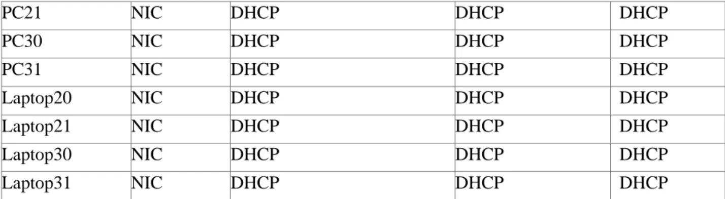
6
PC21 NIC DHCP DHCP DHCP
PC30 NIC DHCP DHCP DHCP
PC31 NIC DHCP DHCP DHCP
Laptop20 NIC DHCP DHCP DHCP
Laptop21 NIC DHCP DHCP DHCP
Laptop30 NIC DHCP DHCP DHCP
Laptop31 NIC DHCP DHCP DHCP
Tabla de asignación de VLAN y de puertos
Dispositivo VLAN Nombre Interfa
z
SW2 100 LAPTOPS Fa0/2-3
SW2 200 DESTOPS Fa0/4-5
SW3 1 - Todas las interfaces
Tabla de enlaces troncales
Dispositivo local Interfaz local Dispositivo remoto
SW2 Fa0/2-3 100
Situación
En esta actividad, demostrará y reforzará su capacidad para implementar NAT, servidor de DHCP, RIPV2 y el routing entre VLAN, incluida la configuración de direcciones IP, las VLAN, los enlaces troncales y las subinterfaces. Todas las pruebas de alcance deben realizarse a través de ping únicamente.
Descripción de las actividades
SW1 VLAN y las asignaciones de puertos de VLAN deben cumplir con la tabla 1. Los puertos de red que no se utilizan se deben deshabilitar.
La información de dirección IP R1, R2 y R3 debe cumplir con la tabla 1. Laptop20, Laptop21, PC20, PC21, Laptop30, Laptop31, PC30 y PC31
deben obtener información IPv4 del servidor DHCP.
7 R1 debe tener una ruta estática predeterminada al ISP que se configuró y
que incluye esa ruta en el dominio RIPv2.
R2 es un servidor de DHCP para los dispositivos conectados al puerto FastEthernet0/0.
R2 debe, además de enrutamiento a otras partes de la red, ruta entre las VLAN 100 y 200.
El Servidor0 es sólo un servidor IPv6 y solo debe ser accesibles para los dispositivos en R3 (ping).
La NIC instalado en direcciones IPv4 e IPv6 de Laptop30, de Laptop31, de PC30 y obligación de configurados PC31 simultáneas (dual-stack). Las direcciones se deben configurar mediante DHCP y DHCPv6.
La interfaz FastEthernet 0/0 del R3 también deben tener direcciones IPv4 e IPv6 configuradas (dual- stack).
R1, R2 y R3 intercambian información de routing mediante RIP versión 2.
R1, R2 y R3 deben saber sobre las rutas de cada uno y la ruta predeterminada desde R1.
9 PASO 2. CONFIGURACIÓN BÁSICA DE LOS ROUTER Y SWITCHES
Router ISP
Router>ena Router#config t
Enter configuration commands, one per line. End with CNTL/Z. Router(config)#no ip domain-lookup Router(config)#hostname ISP ISP(config)#enable secret class ISP(config)#service
password-encryption ISP(config)#line con 0 line)#password cisco ISP(config-line)#login ISP(config-line)#logging synchronous ISP(config-line)#exit ISP(config)#line vty 0 15 ISP(config-line)#password cisco
ISP(config-line)#login ISP(config-line)#exit
ISP(config)#banner motd #Acesso solo a personal autorizado# ISP(config)#
Router R1
Router>ena Router#config t
Enter configuration commands, one per line. End with CNTL/Z. Router(config)#no ip domain-lookup Router(config)#hostname R1 R1(config)#enable secret class R1(config)#service
password-encryption R1(config)#line con 0 line)#password cisco R1(config-line)#login R1(config-line)#logging synchronous R1(config-line)#exit R1(config)#line vty 0 15 line)#password cisco R1(config-line)#login R1(config-line)#exit
R1(config)#banner motd #Acceso solo a personal autorizado# R1(config)#
Router R2
Router>ena Router#config t
Enter configuration commands, one per line. End with CNTL/Z. Router(config)#no ip domain-lookup Router(config)#hostname R2 R2(config)#enable secret class R2(config)#service
R2(config-10 line)#login R2(config-line)#logging synchronous
R2(config-line)#exit R2(config)#line vty 0 15 line)#password cisco R2(config-line)#login R2(config-line)#exit
R2(config)#banner motd #Acceso solo a personal autorizado# R2(config)#end
Router R3
Router>ena Router#config t
Enter configuration commands, one per line. End with CNTL/Z. Router(config)#no ip domain-lookup Router(config)#hostname R3 R3(config)#enable secret class R3(config)#service
password-encryption R3(config)#line con 0 line)#password cisco R3(config-line)#login R3(config-line)#logging synchronous R3(config-line)#exit R3(config)#line vty 0 15 line)#password cisco R3(config-line)#login R3(config-line)#exit
R3(config)#banner motd #Acceso solo a personal autorizado# R3(config)#end
Switch 2
Switch>ena Switch#config t
Enter configuration commands, one per line. End with CNTL/Z. Switch(config)#hostname Switch_2
Switch_2(config)#enable secret class
Switch_2(config)#servive password-encryption ^
%Invalid input detected at '^' marker.
Switch_2(config)#service password-encryption Switch_2(config)#line con 0 Switch_2(config-line)#password cisco Switch_2(config-line)#login Switch_2(config-line)#logging synchronous Switch_2(config-line)#exiy
^
%Invalid input detected at '^' marker.
11 line)#login
Switch_2(config-line)#exit
Switch_2(config)#banner motd #Acceso solo a personal autorizado#
Switch_2(config)#end
Switch 3
Switch>ena Switch#config t
Enter configuration commands, one per line. End with CNTL/Z. Switch(config)#hostname Switch_3
Switch_3(config)#service password-encryption Switch_3(config)#enable secret class
Switch_3(config)#line con 0
Switch_3(config-line)#password cisco Switch_3(config-line)#login
Switch_3(config-line)#logging synchronous Switch_3(config-line)#exit
Switch_3(config)#line vty 0 15 line)#password cisco
Switch_3(config-line)#login Switch_3(config-line)#exit
Switch_3(config)#banner motd #Acceso solo a personal autorizado# Switch_3(config)#end
12 PASO 3. CONFIGURACIÓN DE LA TABLA DE DIRECCIONAMIENTO EN LOS
ROUTER
Router ISP
Press RETURN to get started!
Acesso solo a personal autorizado
User Access Verification
Password:
ISP>ena Password: ISP#config t
Enter configuration commands, one per line. End with CNTL/Z. ISP(config)#int s0/0/0
if)#ip address 200.123.211.1 255.255.255.0 ISP(config-if)#no shutdown
13
Router R1
R1#config t
Enter configuration commands, one per line. End with CNTL/Z. R1(config)#int s0/0/0
if)#ip address 200.123.211.2 255.255.255.0 R1(config-if)#no shutdown
R1(config-if)#
%LINK-5-CHANGED: Interface Serial0/0/0, changed state to up
R1(config-if)#int s0/
%LINEPROTO-5-UPDOWN: Line protocol on Interface Serial0/0/0, changed state to up
R1(config-if)#int s0/1/0
R1(config-if)#ip address 10.0.0.1 255.255.255.252 R1(config-if)#no shutdown
%LINK-5-CHANGED: Interface Serial0/1/0, changed state to down R1(config-if)#int s0/1/1
if)#ip address 10.0.0.5 255.255.255.252 R1(config-if)#no shutdown
%LINK-5-CHANGED: Interface Serial0/1/1, changed state to down R1(config-if)#end
R1#
%SYS-5-CONFIG_I: Configured from console by console
Router R2
R2#config t
Enter configuration commands, one per line. End with CNTL/Z. R2(config)#int s0/0/0
if)#ip address 10.0.0.2 255.255.255.252 R2(config-if)#no shutdown
R2(config-if)#
%LINK-5-CHANGED: Interface Serial0/0/0, changed state to up
R2(config-if)#
%LINEPROTO-5-UPDOWN: Line protocol on Interface Serial0/0/0, changed state to up
R2(config-if)#int s0/0/1
14 R2(config-if)#no shutdown
%LINK-5-CHANGED: Interface Serial0/0/1, changed state to down
Router R3
R3#config t
Enter configuration commands, one per line. End with CNTL/Z. R3(config)#int s0/0/0
if)#ip address 10.0.0.6 255.255.255.252 R3(config-if)#no shutdown
R3(config-if)#
%LINK-5-CHANGED: Interface Serial0/0/0, changed state to up
R3(config-if)#
%LINEPROTO-5-UPDOWN: Line protocol on Interface Serial0/0/0, changed state to up
R3(config-if)#int s0/0/1
R3(config-if)#ip address 10.0.0.10 255.255.255.252 R3(config-if)#np shutdown
^
%Invalid input detected at '^' marker. R3(config-if)#no shutdown
R3(config-if)#
%LINK-5-CHANGED: Interface Serial0/0/1, changed state to up
R3(config-if)#
15 PASO 4. CREACIÓN DE VLAN EN LOS SWITCHES
Switch 2
Switch_2#config t
Enter configuration commands, one per line. End with CNTL/Z. Switch_2(config)#vlan 100
Switch_2(config-vlan)#name LAPTOPS Switch_2(config-vlan)#end
Switch_2#
%SYS-5-CONFIG_I: Configured from console by console Switch_2#config t
Enter configuration commands, one per line. End with CNTL/Z. Switch_2(config)#vlan 200
Switch_2(config-vlan)#name DESTOPS Switch_2(config-vlan)#end
Switch_2#
%SYS-5-CONFIG_I: Configured from console by console
Verificamos que las VLAN se hayan creado correctamente:
Procedemos a asignar los puertos a las VLAN
Switch_2(config)#interface range fa0/2-3
if-range)#switchport mode access Switch_2(config-if-range)#switchport access vlan 100 Switch_2(config-if-range)#end Switch_2#
%SYS-5-CONFIG_I: Configured from console by console
Switch_2#config t
16 Switch_2(config)#interface range fa0/4-5
Switch_2(config-if-range)#switchport mode access Switch_2(config-if-range)#switchport access vlan 200 Switch_2(config-if-range)#end
Switch_2#
%SYS-5-CONFIG_I: Configured from console by console
Verificamos que se encuentren asignados correctamente los puertos a las VLAN
Deshabilitamos los puertos que no están siendo usados
Switch_2#config t
Enter configuration commands, one per line. End with CNTL/Z.
Switch_2(config)#interface range fa0/6-24 Switch_2(config-if-range)#shutdown
Switch 3
Switch_3>ena Password:
Switch_3#config t
Enter configuration commands, one per line. End with CNTL/Z. Switch_3(config)#vlan 1
Switch_3(config-vlan)#exit
Switch_3(config)#int range fa0/1-24
Switch_3(config-if-range)#switchport mode access Switch_3(config-if-range)#switchport access vlan 1 Switch_3(config-if-range)#exit Switch_3(config)#
Deshabilitamos los puertos que no están siendo usados
Switch_3#config t
Enter configuration commands, one per line. End with CNTL/Z.
Switch_3(config)#int range fa0/7-24 Switch_3(config-if-range)#shutdowm ^
17 PASO 5. CREACIÓN DE LOS ENLACES TRONCALES EN LOS SWITCHES
Switch 3
Switch_3(config)#
Switch_3(config)#int f0/1
Switch_3(config-if)#switchport mode trunk Switch_3(config-if)#end Switch_3#
%SYS-5-CONFIG_I: Configured from console by console
Switch 2
Switch_2#config t
Enter configuration commands, one per line. End with CNTL/Z. Switch_2(config)#int f0/1
Switch_2(config-if)#switchport mode trunk Switch_2(config-if)#end
Switch_2#
%SYS-5-CONFIG_I: Configured from console by console
PASO 6. CONFIGURACIÓN DE LAS VLAN EN LOS ROUTER
Router R2
R2#config t
Enter configuration commands, one per line. End with CNTL/Z. R2(config)#inte f0/0.100
R2(config-subif)#encapsulation dot1Q 100
R2(config-subif)#ip address 192.168.20.1 255.255.255.0 R2(config-subif)#int f0/0.200
R2(config-subif)#encapsulation dot1Q 200
R2(config-subif)#ip address 192.168.21.1 255.255.255.0 R2(config-subif)#int 0/0
^
18 %LINK-5-CHANGED: Interface FastEthernet0/0, changed state to up
Router R3
R3#config
Configuring from terminal, memory, or network [terminal]? Enter configuration commands, one per line. End with CNTL/Z. R3(config)#ipv6 unicast-routing R3(config)#int f0/0
R3(config-if)#ip address 192.168.30.1 255.255.255.0 R3(config-if)#ipv6 address 2001:db8:130::9C0:80F:301/64 R3(config-if)#ipv6 dhcp server vlan 1
^
%Invalid input detected at '^' marker. R3(config-if)#ipv6 dhcp server vlan_1 R3(config-R3(config-if)#ipv6 nd other-config-flag R3(config-if)#no shutdown
R3(config-if)#
%LINK-5-CHANGED: Interface FastEthernet0/0, changed state to up
%LINEPROTO-5-UPDOWN: Line protocol on Interface FastEthernet0/0, changed state to up
PASO 7. CONFIGURACIÓN DE LA NAT
Router R1
R1#config t
Enter configuration commands, one per line. End with CNTL/Z.
R1(config)#ip nat pool INSIDE-DEVS 200.123.211.2 200.123.211.128 netmask 255.255.255.0
R1(config)#access-list 1 permit 192 ^
%Invalid input detected at '^' marker. R1(config)#access-list 1 permit 192.168.0.0 0.0.255.255 R1(config)#access-list 1 permit 10.0.0.0 0.0.0.255 R1(config)#ip nat inside source list 1 int s0/0/0 overload R1(config)#int s0/1/0
if)#ip nat inside R1(config-if)#int s0/1/1 R1(config-if)#ip nat inside R1(config-if)#int s0/0/0
19 R1(config-if)#end
R1#
%SYS-5-CONFIG_I: Configured from console by console
PASO 8. CONFIGURACIÓN DE LA RUTA ESTÁTICA PREDETERMINADA AL ISP
R1>en Password: R1#config t
Enter configuration commands, one per line. End with CNTL/Z. R1(config)#ip nat inside source static tcp 192.168.30.6 80 200.123.211.1 80
R1(config)#router rip R1(config-router)#version 2
R1(config-router)#ip route 0.0.0.0 0.0.0.0 s0/0/0 R1(config)#router rip
R1(config-router)#network 10.0.0.4 R1(config-router)#network 10.0.0.0
R1(config-router)#default-information originate R1(config-router)#end
R1#
%SYS-5-CONFIG_I: Configured from console by console
PASO 9. CONFIGURACIÓN DEL SERVIDOR DHCP EN R2 R2>ena
Password: Password: Password: R2#config t
Enter configuration commands, one per line. End with CNTL/Z. R2(config)#ip dhcp excluded-address 10.0.0.2 10.0.0.9 R2(config)#ip dhcp pool INSIDE-DEVS R2(dhcp-config)#network 192.168.20.1 255.255.255.0 R2(dhcp-config)#network 192.168.21.1 255.255.255.0 R2(dhcp-config)#defaul-router 192.168.1.1 ^
%Invalid input detected at '^' marker.
R2(dhcp-config)#default-router 192.168.1.1 R2(dhcp-config)#dns-server 0.0.0.0 R2(dhcp-config)#exit
20 PASO 10. CONFIGURACIÓN DEL R2 DEBE, ADEMÁS DE ENRUTAMIENTO A OTRAS
PARTES DE LA RED, RUTA ENTRE LAS VLAN 100 Y 200.
R2(config)#int vlan 100
R2(config-if)#ip address 192.168.20.1 255.255.255.0
%192.168.20.0 overlaps with FastEthernet0/0.100 R2(config-if)#exit
R2(config)#int vlan 200
R2(config-if)#ip address 192.168.21.1 255.255.255.0
%192.168.21.0 overlaps with FastEthernet0/0.200 R2(config-if)#end
R2#
%SYS-5-CONFIG_I: Configured from console by console
R2>ena Password: R2#config t
Enter configuration commands, one per line. End with CNTL/Z. R2(config)#router rip
router)#version 2 router)#network 192.168.30.0 router)#network 192.168.20.0 router)#network 192.168.21.0 router)#network 10.0.0.0
R2(config-router)#network 10.0.0.8 R2(config-router)#
R3#config t
Enter configuration commands, one per line. End with CNTL/Z. R3(config)#router rip
router)#version 2 router)#network 192.168.0.0 router)#network 10.0.0.8
21 PASO 11. VERIFIQUE LA CONECTIVIDAD. TODOS LOS TERMINALES DEBEN
PODER HACER PING ENTRE SÍ Y A LA DIRECCIÓN IP DEL ISP. LOS
22 ESCENARIO 2
23 1. CONFIGURAR EL DIRECCIONAMIENTO IP ACORDE CON LA TOPOLOGÍA DE
RED PARA CADA UNO DE LOS DISPOSITIVOS QUE FORMAN PARTE DEL ESCENARIO
Diseñamos la topología en el simulador de Packet Tracer: Se agregó un servidor web a la topología ya que R2 no soporta el servicio HTTP
Configuramos el direccionamiento IP de los router
Router R1
Router>ena Router#config t
Enter configuration commands, one per line. End with CNTL/Z. Router(config)#no ip domain-lookup Router(config)#hostname R1 R1(config)#enable secret class R1(config)#line con
24 R1(config)#banner motd #Acceso solo a personal autorizado#
R1(config)#int s0/0/0
R1(config-if)#ip address 172.31.21.1 255.255.255.252 R1(config-if)#clock rate 128000
R1(config-if)#no shut
%LINK-5-CHANGED: Interface Serial0/0/0, changed state to down R1(config-if)#
Router R2
Router#config t
Enter configuration commands, one per line. End with CNTL/Z. Router(config)#no ip domain-lookup
Router(config)#hostname R2 R2(config)#enable secret class R2(config)#ine con 0
^
%Invalid input detected at '^' marker.
R2(config)#line con 0 R2(config-line)#pass cisco R2(config-line)#login R2(config-line)#line vty 0 15 R2(config-line)#pass cisco R2(config-line)#login R2(config-line)#exit R2(config)#service password-encryption
R2(config)#banner motd #Acceso solo a personal autorizado# R2(config)#int s0/0/0
if)#ip address 172.31.23.1 255.255.255.252 R2(config-if)#clock rate 128000 R2(config-if)#no shut
%LINK-5-CHANGED: Interface Serial0/0/0, changed state to down R2(config-if)#int s0/0/1
if)#ip address 172.31.21.2 255.255.255.252 R2(config-if)#no shut
R2(config-if)#
%LINK-5-CHANGED: Interface Serial0/0/1, changed state to up
%LINEPROTO-5-UPDOWN: Line protocol on Interface Serial0/0/1, changed state to up
R2(config-if)#int f0/0 R2(config-if)#description conexion a ISP
if)#ip address 209.165.200.225 255.255.255.248 R2(config-if)#no shut
R2(config-if)#
25 %LINEPROTO-5-UPDOWN: Line protocol on Interface FastEthernet0/0, changed
state to up
Router R3
Router>ena Router#config
Configuring from terminal, memory, or network [terminal]? Enter configuration commands, one per line. End with CNTL/Z. Router(config)#no ip domain-lookup
Router(config)#hostname R3 R3(config)#enable secret class R3(config)#line con 0
R3(config-line)#pass cisco R3(config-line)#login
R3(config-line)#line vty 0 15 R3(config-line)#pass cisco R3(config-line)#login R3(config-line)#exit
R3(config)#banner motd #Acceso solo a personal autorizado# R3(config)#service password-encryption R3(config)#int s0/0/1 if)#ip address 172.31.23.2 255.255.255.252 R3(config-if)#no shut
R3(config-if)#
%LINK-5-CHANGED: Interface Serial0/0/1, changed state to up
%LINEPROTO-5-UPDOWN: Line protocol on Interface Serial0/0/1, changed state to up
R3(config)#int lo4
R3(config-if)#
%LINK-5-CHANGED: Interface Loopback4, changed state to up
%LINEPROTO-5-UPDOWN: Line protocol on Interface Loopback4, changed state to up
26 R3(config-if)#no shut
R3(config-if)#int lo5
R3(config-if)#
%LINK-5-CHANGED: Interface Loopback5, changed state to up
%LINEPROTO-5-UPDOWN: Line protocol on Interface Loopback5, changed state to up
R3(config-if)#ip address 192.168.5.1 255.255.255.0 R3(config-if)#no shut
R3(config-if)#int lo6
R3(config-if)#
%LINK-5-CHANGED: Interface Loopback6, changed state to up
%LINEPROTO-5-UPDOWN: Line protocol on Interface Loopback6, changed state to up
R3(config-if)#ip address 192.168.6.1 255.255.255.0 R3(config-if)#no shut
27
Switch S1
Switch>ena Switch#config t
Enter configuration commands, one per line. End with CNTL/Z. Switch(config)#no ip domain-lookup Switch(config)#hostname S1 S1(config)#enable secret class S1(config)#line con
0 S1(config-line)#pass cisco S1(config-line)#login S1(config-line)#line vty 0 15 S1(config-line)#pass cisco S1(config-line)#login S1(config-line)#exit S1(config)#service password-encryption
S1(config)#banner motd #Acceso solo a personal autorizado# S1(config)#exit
S1#
%SYS-5-CONFIG_I: Configured from console by console
S1#copy run startup
Destination filename [startup-config]? Building configuration...
[OK] S1#
Switch S3
28 Enter configuration commands, one per line. End with CNTL/Z.
Switch(config)#no ip domain-lookup Switch(config)#hostname S3 S3(config)#enable secret class S3(config)#line con
0 S3(config-line)#pass cisco S3(config-line)#login S3(config-line)#line vty 0 15 S3(config-line)#pass cisco S3(config-line)#login S3(config-line)#exit S3(config)#service password-encryption
S3(config)#banner motd #Acceso solo a personal autorizado# S3(config)#exit
S3#
%SYS-5-CONFIG_I: Configured from console by console
S3#copy run startup
Destination filename [startup-config]? Building configuration...
[OK] S3#
2. CONFIGURAR EL PROTOCOLO DE ENRUTAMIENTO OSPFV2 BAJO LOS SIGUIENTES CRITERIOS:
OSPFv2 area 0
Configuration Item or Task Specification
Router ID R1 1.1.1.1
Router ID R2
5.5.5.5 Router ID R3
8.8.8.8 Configurar todas las interfaces LAN como pasivas
Establecer el ancho de banda para enlaces seriales
en 256 Kb/s
Ajustar el costo en la métrica de S0/0 a 9500
Router R1
R1#config t
Enter configuration commands, one per line. End with CNTL/Z. R1(config)#router ospf 1
29 router)#network 192.168.30.0 0.0.0.3 area 0
R1(config-router)#network 192.168.40.0 0.0.0.3 area 0 R1(config-R1(config-router)#network 192.168.30.0 0.0.0.255 area 0 R1(config-router)#network 192.168.40.0 0.0.0.255 area 0 R1(config-router)#network 192.168.200.0 0.0.0.255 area 0 R1(config-router)#passive-interface f0/1.30
%Invalid interface type and number router)#passive-interface f0/0.30 %Invalid router)#passive-interface type and number R1(config-router)#passive-interface f0/0 R1(config-router)#auto-cost reference-bandwidth 9500 % OSPF: Reference reference-bandwidth is changed.
Please ensure reference bandwidth is consistent across all routers.
R1(config-router)#exit R1(config)#int s0/0/0
R1(config-if)#bandwidth 256 R1(config-if)#ip ospf cost 9500 R1(config-if)#end
R1#
%SYS-5-CONFIG_I: Configured from console by console
Router R2
R2#config t
Enter configuration commands, one per line. End with CNTL/Z. R2(config)#router ospf 1
R2(config-router)#router-id 5.5.5.5
R2(config-router)#network 172.31.21.0 0.0.0.3 area 0 R2(config-router)#network 172.31.21.0 0.0.0.3 area 0
00:55:46: %OSPF-5-ADJCHG: Process 1, Nbr 1.1.1.1 on Serial0/0/1 from LOADING to FULL, Lding Done
^
% Invalid input detected at '^' marker. R2(config-router)#network 172.31.23.0 0.0.3 area 0 ^
% Invalid input detected at '^' marker. R2(config-router)#network 172.31.23.0 0.0.0.3 area 0 R2(config-router)#network 10.10.10.0 0.0.0.255 area 0 router)#passive-interface f0/0 R2(config-router)#auto-cost reference-bandwidth 9500 % OSPF: Reference bandwidth is changed.
Please ensure reference bandwidth is consistent across all routers.
30 R2(config-if)#int s0/0/1
R2(config-if)#bandwidth 256 R2(config-if)#int s0/0/0
R2(config-if)#ip ospf cost 9500 R2(config-if)#exit
R2(config)#
Router R3
R3#config
Configuring from terminal, memory, or network [terminal]? Enter configuration commands, one per line. End with CNTL/Z. R3(config)#router ospf 1
R3(config-router)#router-id 8.8.8.8 R3(config-router)#network 172.31.23.0 0.0.0.3 area 0 R3(config-router)#
01:01:48: %OSPF-5-ADJCHG: Process 1, Nbr 5.5.5.5 on Serial0/0/1 from LOADING to FULL, Loading Done
R3(config-router)#network 192.168.4.0 0.0.3.255 area o ^
% Invalid input detected at '^' marker. R3(config-router)#network 192.168.4.0 0.0.3.255 area 0 R3(config-router)#passive-interface lo4 interface lo5 R3(config-router)#passive-interface lo6 R3(config-router)#auto-cost reference-bandwidth 9500 % OSPF: Reference bandwidth is changed.
Please ensure reference bandwidth is consistent across all routers.
R3(config-router)#exit R3(config)#int s0/0/1
R3(config-if)#bandwidth 256 R3(config-if)#exit
R3(config)#
Verificar información de OSPF
31 Visualizar lista resumida de interfaces por OSPF en donde se ilustre el costo de cada interface
32 3. CONFIGURAR VLANS, PUERTOS TRONCALES, PUERTOS DE ACCESO,
ENCAPSULAMIENTO, INTER-VLAN ROUTING Y SEGURIDAD EN LOS SWITCHES ACORDE A LA TOPOLOGÍA DE RED ESTABLECIDA. S1#config t
Enter configuration commands, one per line. End with CNTL/Z. S1(config)#vlan 30 S1(config-vlan)#name Administracion S1(config-vlan)#vlan 40 S1(config-vlan)#name Mercadeo S1(config-vlan)#vlan 200 S1(config-vlan)#name Mantenimiento S1(config-vlan)#exit S1(config)#
S1(config-if)#ip add 192.168.99.2 255.255.255.0 S1(config-if)#no shutdown
S1(config-if)#exit
S1(config)#ip default-gateway 192.168.99.1 S1(config)#int f0/3
S1(config-if)#switchport mode trunk S1(config-if)#
%LINEPROTO-5-UPDOWN: Line protocol on Interface FastEthernet0/3, changed state to down
%LINEPROTO-5-UPDOWN: Line protocol on Interface FastEthernet0/3, changed state to up
%LINEPROTO-5-UPDOWN: Line protocol on Interface Vlan200, changed state to up if)#switchport trunk native vlan 1
S1(config-if)#int f0/24 S1(config-if)#switchport mode trunk if)#switchport trunk native vlan 1 S1(config-if)#int range f0/2, f0/4-23 S1(config-if-range)#switch mode access S1(config-if-range)#int f0/1 S1(config-if)#switch mode access S1(config-if)#switch access vlan
% Incomplete command. S1(config-if)#switch access vlan 30 S1(config-if)#int range f0/2, f0/4-23
S1(config-if-range)#shutdown
R1#config t
Enter configuration commands, one per line. End with CNTL/Z. R1(config)#int f0/1.30
33 subif)#ip add 192.168.30.1 255.255.255.0
R1(config-subif)#int f0/1.40 R1(config-subif)#ip add 192.168.40.1 255.255.255.0
%Configuring IP routing on a LAN subinterface is only allowed if that subinterface is already configured as part of an IEEE 802.10, IEEE 802.1Q, or ISL vLAN.
R1(config-subif)#
R1(config-subif)#int f0/1.40
R1(config-subif)#encapsulation dot1q 40
R1(config-subif)#ip add 192.168.40.1 255.255.255.0 R1(config-subif)#int f0/1.200
R1(config-subif)#encapsulation dot1q 200
R1(config-subif)#ip add 192.168.200.1 255.255.255.0 R1(config-subif)#exit
R1(config)#
4. En el Switch 3 deshabilitar DNS lookup Esta configurado desde el inicio 5. Asignar direcciones IP a los Switches acorde a los lineamientos.
6. Desactivar todas las interfaces que no sean utilizadas en el esquema de red.
7. Implement DHCP and NAT for IPv4
8. Configurar R1 como servidor DHCP para las VLANs 30 y 40.
9. Reservar las primeras 30 direcciones IP de las VLAN 30 y 40 para configuraciones estáticas.
Name: ADMINISTRACION Configurar DHCP pool para VLAN DNS-Server: 10.10.10.11
30 Domain-Name: ccna-unad.com
Establecer default gateway. Name: MERCADEO Configurar DHCP pool para VLAN DNS-Server: 10.10.10.11
40 Domain-Name: ccna-unad.com
34 R1(config)#
R1(config)#ip dhcp excluded-address 192.168.30.1 192.168.30.30 R1(config)#ip dhcp excluded-address 192.168.40.1 192.168.40.30 R1(config)#ip dhcp pool Administracion R1(dhcp-config)#dns-server 10.10.10.11 R1(dhcp-config)#default-router 192.168.30.1 R1(dhcp-config)#network 192.168.30.0 255.255.255.0
R1(dhcp-config)#ip dhcp pool Mercadeo R1(dhcp-config)#dns-server 10.10.10.11 R1(dhcp-config)#default-router 192.168.40.1 R1(dhcp-config)#network
192.168.40.0 255.255.255.0 R1(dhcp-config)#exit
R1(config)#
10. Configurar NAT en R2 para permitir que los host puedan salir a internet
R2#config t
Enter configuration commands, one per line. End with CNTL/Z.
R2(config)#user webuser privilege 15 secret cisco12345 R2(config)#ip http server
^
% Invalid input detected at '^' marker. R2(config)#
Dado que no se puede utilizar los comandos ip http server se emplea un servidor dentro de la topología
R2(config)#
R2(config)#ip nat inside source static 10.10.10.10 209.165.200.229
R2(config)#int f0/0
35 11. Configurar al menos dos listas de acceso de tipo estándar a su criterio en para restringir
o permitir tráfico desde R1 o R3 hacia R2.
R2(config)#access-list 1 permit 192.168.30.0 0.0.0.255 R2(config)#access-list 1 permit 192.168.40.0 0.0.0.255 R2(config)#ip nat pool INTERNET 209.165.200.225 209.165.200.228 netmask 255.255.255.248
R2(config)#ip nat inside source list 1 pool INTERNET R2(config)#exit
R2#
%SYS-5-CONFIG_I: Configured from console by console
R2(config)#ip access-list standard ADMIN_S
std-nacl)#permit host 172.31.21.1 std-nacl)#exit R2(config)#line vty 0 4 R2(config-line)#access-class ADMIN_S in R2(config-line)#
12. Configurar al menos dos listas de acceso de tipo extendido o nombradas a su criterio en para restringir o permitir tráfico desde R1 o R3 hacia R2.
R2(config)#access-list 101 permit tcp any host 209.165.200.229 eq www
R2(config)#access-list 101 permit icmp any any echo-reply R2(config)#int f0/0
R2(config-if)#ip access-group 101 in R2(config-if)#int s0/0/0
R2(config-if)#ip access-group 101 out R2(config-if)#int s0/0/1
R2(config-if)#ip access-group 101 out R2(config-if)#int f0/1
R2(config-if)#ip access-group 101 out R2(config-if)
36 CONCLUSIONES
Se practicó todo lo relacionado con la configuración de router 1841, probando paso a paso cada uno de los comandos escritos a fin de evaluar su funcionamiento dentro
del archivo de configuración.
Se usaron los atajos propuestos por el modulo a la hora de realizar configuraciones
desde la consola como parte de la práctica.
Se consultaron diversos medios como videos y páginas de internet con el fin de reforzar los conocimientos y despejar dudas al momento de adelantar configuraciones en los routers.
Se realizaron variaciones en las configuraciones a fin de generar fallas que
37 BIBLIOGRAFIA
CISCO. (2014). Exploración de la red. Fundamentos de Networking. Recuperado de
https://static-course-
assets.s3.amazonaws.com/ITN50ES/module1/index.html#1.0.1.1
CISCO. (2014). Capa de Transporte. Fundamentos de Networking. Recuperado de
https://static-course-
assets.s3.amazonaws.com/ITN50ES/module7/index.html#7.0.1.1
CISCO. (2014). Asignación de direcciones IP. Fundamentos de Networking. Recuperado de https://static-course-
assets.s3.amazonaws.com/ITN50ES/module8/index.html#8.0.1.1
CISCO. (2014). Introducción a redes conmutadas. Principios de Enrutamiento y Conmutación. Recuperado de https://static-course-
assets.s3.amazonaws.com/RSE50ES/module1/index.html#1.0.1.1
CISCO. (2014). Configuración y conceptos básicos de Switching. Principios de Enrutamiento y Conmutación. Recuperado de https://static-course- assets.s3.amazonaws.com/RSE50ES/module2/index.html#2.0.1.1
CISCO. (2014). VLANs. Principios de Enrutamiento y Conmutación. Recuperado de https://static-course-
38 CISCO. (2014). Introducción a redes conmutadas. Principios de Enrutamiento y
Conmutación. Recuperado de https://static-course-
assets.s3.amazonaws.com/RSE50ES/module1/index.html#1.0.1.1