SYNTHESIS OF CIRCULARLY POLARISED RADIAL LINE SLOT ARRAY Manuel SierraPl ,Maria Vera Isasa , Antonio G. Pino , Manuel Sierra C.'
'Universidad
Polit6cnica
de Madrid. E.T.S.I. Telecomunicaci6n. Ciudad Universitaria 28040 Madrid (Spain). Phone: +3415495700 Fax: +3414532002. E-mail:[email protected]2Universidad
deVigo. E.T.SI Telecomunicaci6n.36200
Vigo
(Spain).
Phone:+3486812117 E-mail:[email protected] ABSTRACTIn previous articles,aneasy waytoanalyse a slot array fed through aradial line was presented. The analysis was based
on acircuitapproach where circuit parameters have been estimated using the first propagation mode in the radial line and the farfieldtheory. Here we study the design of a particular application for circularly polarised broadside antenna. The design defines thelength, position and orientation of the slots in the antenna surface. The final analysis of the antenna gives a good behaviour in field diagrams and gain.
INTRODUCTION
Antennas based on narrow slots directlycoupled to a radial line have been used previouslyinDirect Broadcast Satellite (DBS) receivers [1] and mobilecommunications [2]. One of the most important features for such antennas is their low costand low loss feedingline. This paper shows a synthesis method to define the length, position and orientation of slots
on theantenna surface. The basic model is based on the assumption that fundamental TEM mode keeps is original
structure overthe radialline, except for the attenuation due to the slot power coupling. Changes in phase in the coupled field duetothe slot resonance must be taken into account to obtain an uniform phase aperture field. Finally second order effects like the change in the field phase or field reflections must be included in the design process. The antenna final analysis using the equivalent circuit analysis method developed by the authors [3], [41 give a good behaviour of the
antenna.
ANTENNA BASICSTRUCTURE: FIRSTDESIGN
Theradial line is a parallel plate structure, fedatitcentreby the penetration ofthe inner conductor of a coaxial probe. The space between theplates (h) is less thanhalf wavelength,soonly the TEM modecanpropagatebetween them. The slots
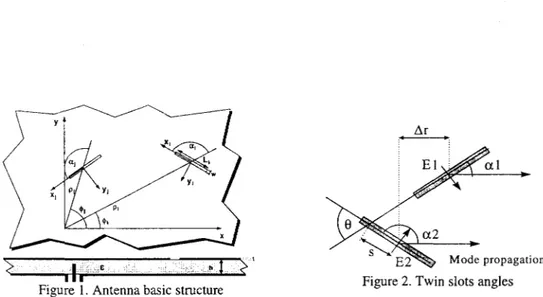
areplacedonthe upper plateof the radial line. FigureIshows the antenna structure and thedesign variables for each slot: slotlength(Li), tilt angle between the slot and the radial line
(ai)
and slot position referred to thefeeding point(Pi,°i) Other parameters areconsideredasconstants: slot with (w), metal thickness (t) or dielectric inside the waveguide(E).The original field inside the radial line can be considered as an ideal TEM mode with symmetry of revolution, and far from thecoaxial probe can be written like-
2 F
(~~~~~~kpJjl
E(p)
=4[Ele
jz
(1)
H(p)-=
3[E,e{
4)Jj
(2)
TWIN SLOTS FOR CIRCULARLY POLARISED FAR FIELD
Theslotsare narrow and close to resonance, so we can assume uniform field in the narrow dimension and cosine in the resonant dimension, giving alinearly polarised radiated field. To obtain the circular polarisation we must combine at least two slots as shown in figure 2. The relative field in the slots must satisfy thecondition:
R EL'L | (3)
Ar
E1
.,I:
2
Modepropagationilk
Figure 1. Antenna basic structure Figure 2. Twin slots angles
Thefield phase can be obtained moving the slots along the radial direction (Ar). The sign of previous equation depends on the desired polarisation. The parameter "s" is a final free parameter defining the relative position of the slots, and has
beenadjusted tominimize the coupling effect on the radiated field polarisation. APERTUREPHASE: SLOT POSITION
Keepingconstantthe slotradial tilt angle (a), the far field phase from each slot twin depends on it orientation and must be compensated through the distance to the feeding point. This condition gives the position of slots over an spiral. To keep
thespace between slot pairs constant, an iterativeformulaisapplied:
P+ ,
Pi
d (5)41± 2As
+(2i7
)p
-
+
-
-a+r0=±+7+
(6)
g g
where
ye
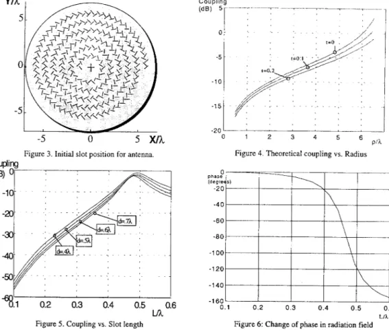
isaconstantand disthedistance from slot pairs. Figures 3 shows the relative slot position obtainedinthecaseofoc=it/4,
d=Xg/2
andyo=O.
APERTURE MAGNITUDE: SLOT LENGTH
Thecoupled fieldtoslotsdependsontheslotposition,tiltangle and length. Keepingconstanttheangle, the field inside theguide spreads andattenuates inprevious slots and the slot lengthmustgrow from thecentreto theantennaborder.
Assunring
each slot turnsas acoupling element andthe field attenuation is uniform(keeping the symmetry), aclosedformula for the slotcouplingcanbedevelopedas:
Pt(P
2p(7)
2
2__
((P,
+Pmim
05X)wherepmxandP",,arethemaximum and minimumdistances from the feedingpoint,andtisthepowerfractionoverthe final load.Figure4shows thecouplingversusdistancefrom thecentrefora6Xantennaradius. The slotcoupling depends
on the slot length like a resonantcavity and canbe computed froman equivalent circuit like shown in figure 5. Not always ispossibletoreach theestimated couplingand themaximumisassumed for the lastslots.
PHASE CHANGE DUE TO SLOT RESONANCE
The slotfieldphasechangesfromtheidealfield inside deguide due first to theslotresonanceandsecond tofieldphase
changeswhen coupledtopreviousslots.Ingeneral these changesare lower thani/4butaddwith thesamesign andcan lowertheantennaefficiencyasmuchas3dB. Tocompensatethem, the slots aremoved towardthe centreoftheantenna. Thischangeinslotposition allowsreducing the wavelengthinthe guidekeepingthe grating lobes undercontrol,without
-574-I
.~~~~~~~~~~~~~~~~~~~~~~~~~~~~~~~~~~~~~~~~~~~~~~~~~~~~~~~~~~~~~~I,.:.:
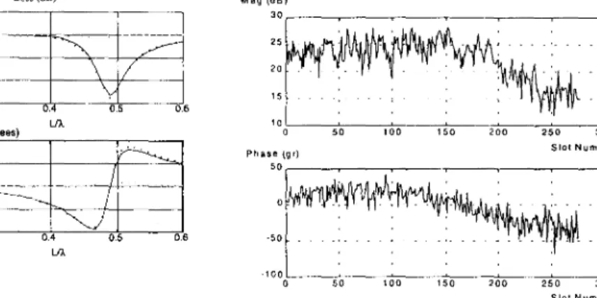
using anydielectric. The phasecihan2gedue totheslot iesonanceisshown in figure 6. In fgure 7 we
presenit
the change in phase and amplitude ofthe wave after a ring of several slots. Both graphics can be writtendepending
on theparametersof thecircuitapproachi.
YAk
5S-5
Coupling (dB)
5F
0
-5
-10
-15
-20L
0
1=0
2 3 4 $ 6
pfX
Figure 3. Initial slot position for antenna.
Figure
4.Theoreticalcoupling
vs.Radius0.5 0.6
LA,
Figure 5.Couplingvs.Slotlength
-160'
0.1 0.2 0.3 0.4 0.5 0.6
Figure
6:Change
ofphase
inradiation field LIOThese changes of phaseproduceachangeintheposition of the slots, thatcanbewrittenas:
A
Ap
=-fw(+
(8)FIELD
REFLECTIONThe field reflected in the slots creates an incoming mode that is not absorbed by the coaxial probe and propagates
outward. Thismode can bedescribedas aTEM modewith a spiralphasefront like:
(9)
where is areflectioncoefficient that dependsontheslot coupling. Thisfield addstothemainfield mode andcreatesan
asymmetry in the aperturefield, reducing the apertureefficiency and rising the lateral lobes. The asymmetry is more
important in small antennas, where slot couplingis larger.To avoid theinfluence ofthe reflected mode, the slots are moved again frorn its previous position but now in a non symmetric way. They are moved a small fraction of the
wavelength inarandomway. This displacementchanges slightly the phase of the reflected field and it influence in the
finalslotfield, although doesnotavoid the reflection.
En
=ErF
l 2 etjke
p)
e'j2(0
n)
Afterconsiderinlg allthese effects we can calculate the field overeachslot with the analysismeLhod
described
int4I.
Infigure8 wepresentthemagnitudeanldphase of the field overeachslotfor a 275 slots
anitennia.
Loss (dB)
-4
-6___-____. _
01 0.2 0.3 04 0 5 0.6
20 Phase(degrees)
-10
0-1 0.2 0.3 0.4 0.5 0.6
1/h
Figure 7.Change of phase after a ring ofslots
Mag(d4) 30
2 5.
20
.5>..'
o
10 .
0 50 100 150 200 250 300
Phase(gr) SlotNurnbe
Slot Number
Figure 8. Final field over the slots
ANALYSIS
We designed an antenna based on this philosophy to be used for the reception ofDBS with the Spanish Satellite
HISPASAT. Thefrequency bandwas 12.1 -12.5 GHz, left circular
polanisation.
Weimposedamaximum diameter of300 mm. The bestdesignwecouldgetwiththeselimitswere:
* Slotwidth: 1,5mm
* Metal plate thickness. 0,1mm * Distance between metalplates: 8mm
* Theradialguide isfinished inashort-circuit.
* Dielectricmaterial: £= 1,1 (honeycomb)
* Coaxial probe: SMA (50 ohm and0,65mm)
* Gain=29,5 dBi
* SLLbetterthan-13,5dBin thefrequency band
* S1lbetter than-17dBlinthe frequency band
* Beamwidth=50
MULTIPROBE FEED: SECOND DESIGN
The effects of the reflection fieldcan beeliminated ifweplace the slots in concentricrings. Thatmeans wehave to
generate a
cilindric
wave, whose phasefrontsareArchimedes
spirals instead ofgeneratingaradialwavewiththe slots placedformingaspiral.DESIGN OF THE COAXIAL PROBES
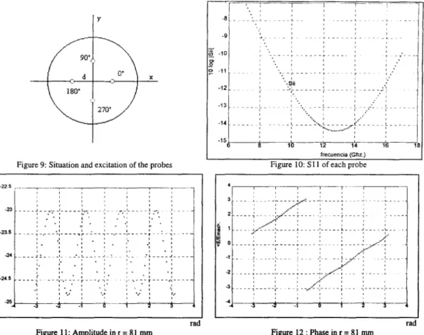
This isgotifyou excitetheantennawith four coaxial probes, andyoufeedeachonewithphasechangesof
900.
Thepurityof the spiralwave front depends onthe separationof the four probes. The mode is better when the probes are
closer, but the impedance bandwidth is perturbed when the probes are very close. We got an optimum value for a
separationof4mmfromthe centreof theantenna toeachprobe. Anschemeofthe coaxialprobesisshowninfigure9. With this value we estimate the impedance of each element in figure 10. In figure 11 and
figure
12 we show theamplitude and phase of the electric field81 mmfromthe centreof theantenna.
Theequivalentcircuitof thefourprobesiscalculatedas afourportsmultipolewherethe mutualimpedancesfollow the
nextformula:
.-i7-k
~~~4hGG.'~~~~~~~~~
,F
z G G X
-eJ(
kpq 4)G=cos(cSI
)-cos(k(L,
+34~))
I
sen(k(L
+54.))
Figure9:Situation and excitation of theprobes
-22,5
-23.5 -4
---.24 ----5
-24.5-rad Figure11.
Amnplitude
inr 81mnuFigure10: 511Iof eachprobe
3
2
U ±~~~~~~
rad Figure12:Phasexinr 81mmu
Theexcitation circuitmustbe verysimplein ordertominimize the finalcostof theproduct. Wedesignedaserialcircuit,
whereweadapteachprobe varyingthewidth of themicrostriplines. Thecircuit iscomposed by threeXg/4microstrip lines.
DESIGN OF THESLOTS
We have thesamedesignwehadintheprevioussectioninseveralaspects. We calculate thepositionof thetwoslotsto
getthecircularpolarisation,the slotlengthand width andweapplythecorrectionsduetotheresonanceof the radiant and incdentfield in the sameway wedid before. Theonly difference is we generate nowa wave whose phase front is a spiral.
Ifwewant togetacircularpolarisedantennawedonothavetomodifythatphasewith thedifferentpositionof the slots.
Thatmeans we can placethecoupleof slotsinconcentricrings, where each ringisseparated X.~of the previousone,in ordertoaddinphasethe radiated field of each slot.
Whenweplacetheslots inconcentricrings the reflected field doesnot dependontheangle,so we aregoingtohavean
uniform hield. Thepositionof the first ringisgoingtofix the effect of the reflected fieldoverthe total field.
Thepositionofthe shortcircuitweplaced atthe end of theantenna isdifferenttoo. That shortcircuit hastobeplaced
?±g/4from thecentreof the last slot. Inthe firstdesignithadtobeanArchimedes spiral butnowitisacircumference,
(I11)
-90
-13
-14
6 8 10 12 14 16 8
niuch easier to manufacture. Te reflected field on that short-circuit will no depend on the angle, so the design will be easiertooptimise In this case the electric fieldintheguideisshowninEc. 12.
En
xo ecee-jkp
j
(12)Anscheme of the array is showninfigure 13. Figure14showsthe radiated field (copolar and crosspclar) obtained with a five-turns circular array of 9.4-10.2 mm. slots, analyzed at 12.1 GHz. This means a 30cm. antennadiameterwith good characteristics to receive satellite communications.
150 0
100 1-5/ ~YV
I / / //
-~~~~~~~15
mm
<20
71- 7 ~~~~~~~~~~~ ~~~-25IIF 14: dB
-_IM~~~~~~~~~~~~~~~~~~~~~~~~~~~~~~~I
-150 -100 -50 0 50 100 150 "
mm ~~~~
~~~~~~~~-40
lI~'-80 -6 40 -20 0 20 40 60580
Figure13.
irculararay
antennaFigure
14 Copolar-Contrapolarradiationpaftern
Figu}re13.Circulararrayantenna
CONCLUSIONS
Thispaperdescribes theway todesign theantenna, giving the slotposition andangleto getaradial line slotantenna
having circular polarisation and broadside main beam. We show two different techniques; with the first one the
excitation isverysimple, only thecoaxialprobe,while the position of the slots and the final short-circuit iscomplicate. Thisdesign generates a reflected field that dependsontheangle. Tosolve thisproblemwecomplicatetheexcitationof
the antenna(four coaxial probes withonemicrostipcircuit), but theantenna isperfectly symmetrical. Thistechnique
canalso beextendedtoother kind ofantennasanditisspeciallyinteresting for small arrays. REFERENCES
[11
Ando M. "New DBS Receiver Antennas ", 1993, Proc.23rdEuMC, pp. 84-92.[2] Takada J., Tanisho A., Ito K, Ando M., "Circularly polarized conical beam radial line slot antenna", 1994, Electronics Letters,vol. 30,n021,pp.1729-1730.
[3] M. Sierra, J. Redoll,M.Vera, A.G. Pino, "Designandanalysisof slot array antennas onaradial feed line", 1995, Proc.IEEEAP-S, vol. 1, pp.362-365.
[4] M.P.Sierra,M.Vera,A.G.Pino,M.S.Castafier,"Analysis of slotantennas on aradialtransmission line", Intemational Journal of Microwave and Millimeter-Wave Computer-Aided Engineering.