EVALUACIÓN FINAL
PRUEBA DE HABILIDADES PRÁCTICAS CCNP
ROBINSON QUINTERO CAJAMARCA.
UNIVERSIDAD NACIONAL ABIERTA Y A DISTANCIA INGENIERIA ELECTRONICA
DIPLOMADO CISCO BOGOTÁ
EVALUACIÓN PRUEBA DE HABILIDADES PRÁCTICAS CCNP
ROBINSON QUINTERO CAJAMARCA
Diplomado de profundización CCNP prueba de Habilidades prácticas
Gerardo Granados Acuña Magíster en Telemática
UNIVERSIDAD NACIONAL ABIERTA Y A DISTANCIA INGENIERIA ELECTRONICA
DIPLOMADO CISCO CCNP BOGOTÁ
NOTA DE ACEPTACION
_______________________________ _______________________________ _______________________________ _______________________________ _______________________________ _______________________________ _______________________________
Presidente del jurado
Jurado
Jurado
4
CONTENIDO
pag.
INTRODUCCIÓN 3
EJERCICIO ESCENARIO 1 4
EJERCICIO ESCENARIO 2 11
EJERCICIO ESCENARIO 3 20
CONCLUSIONES 34
5
LISTA DE TABLAS
Tabla 1. Direccionamiento Routers 19
Tabla 2. Direcciones IP de los PCs 37
6
LISTA DE FIGURAS
Figura 1. Escenario 1 10
Figura 2. Conexión de Routers 10
Figura 3. Análisis de R3 por comando Show ip route 17 Figura 4. Análisis de R1 por comando Show ip route 18 Figura 5. Análisis de R5 por comando Show ip route 18
Figura 6. Escenario 2 19
Figura 7. Configuración BGP R2 23
Figura 8. Configuración R1 23
Figura 9. Configuración BGP R3 25
Figura 10. Configuración BGP R4 26
Figura 11. Estado de Configuración R3 27 Figura 12. Estado de configuración router 4 27 Figura 13. Prueba de configuración R3 27 Figura 14. Prueba de configuración Router 4 28 Figura 14.1 Prueba de Configuración Router 4 28
Figura 15. Escenario 3 29
Figura 16. Verificación de Configuración Switch 1 30 Figura 17. Verificación de Configuración Switch 2 31 Figura 18. Verificación de Configuración Switch 3 31 Figura 19. Verificación enlace Comando show interfaces trunk de S1 y 2 32 Figura 20. Verificación enlace trunk en Switch 1 34 Figura 21. Configuración enlace "trunk" permanente entre SWT2 y SWT3 35
Figura 22. Verificación VLANs 36
7
Figura 30. Configuración IP Mercadeo (PC7) 40 Figura 31. Configuración IP Compras (PC6) 41
Figura 32. Ejecución Ping PCO 43
8 GLOSARIO
Switch: También llamado conmutador, este dispositivo digital, permite la conexión de dos o mas host con el fin de pasar datos de un segmento a otro.
Router o Enrutador: Es un hardware que tiene la cualidad de interconectar computadores, que se encuentran en red. Este da a cada paquete de datos una ruta dentro de la red.
Cisco Certified Network Professional (CCNP): Es la certificación que da Cisco Systems, a las personas que tienen un conocimiento avanzado en configuración de diferentes protocolos de enrutamiento, Routers, Switch y comprensión del modelo OSI de siete capas y del TCP/IP, entre otros.
VLAN (Virtual LAN) Red de área local y virtual: Es un método que permite crear redes que lógicamente son independientes, aunque éstas se encuentren dentro de un mismo conmutador ó una misma red física, con esto, el usuario puede disponer de varias VlLANs en un mismo Router. Los dispositivos que pertenecen a una VLAN no tendrían acceso a otros que se encuentren en diferentes VLAN.
Packet Tracer: Este es un programa de simulación de redes de CISCO que ayuda a los usuarios a trabajar con simulaciones de redes, para así poder comprender su comportamiento de una forma más didáctica y fácil. Aquí se pueden manejar protocolos simulados de capa de aplicación, y enrutamientos básicos con OSPF, EIGRP entre otros.
Enrutamiento: Esta es una función que ayuda a encontrar la mejor ruta entre diferentes opciones en una red de paquetes, los cuales poseen una gran conectividad.
Protocolos de Enrutamiento: Son un conjunto de normas utilizadas por los Router para comunicarse con otros, para poder compartir información de
9 RESUMEN
El presente trabajo contiene la solución de tres escenarios planteados en la
prueba de habilidades prácticas del diplomado de profundización CCNP, dentro de los cuales en el primero, realizamos las configuraciones iniciales y protocolos de enrutamiento para 5 routers, sin asignación de claves y se configuraron las interfaces con las direcciones indicadas en la tabla correspondiente.
En el segundo escenario, se trabajó configurando la relación de vecino BGP entre cuatro Routers, anunciando las direcciones de Loopback en BGP, codificándole los ID a cada uno de ellos y se crearon rutas estáticas para alcanzar la Loopback 0 del otro Router.
En el tercer escenario se realizó la configuración de tres Switch para usar VTP para poder realizar actualizaciones de VLAN, cada uno de ellos se configuró como servidor, clientes, respectivamente, con dominio VPT llamado CCNP con
contraseña. También se configuró el enlace troncal, trunk, entre SWT1 y SWT2, dichas configuraciones se verificaron con el comando Show vtp status.
10
INTRODUCCIÓN
En el siguiente trabajo encontraremos mediante diferentes ejercicios, en tres escenarios distintos, el contenido total de nuestro Diplomado de Profundización CCNP, con el cual hemos aprendido a darle solución a problemas cotidianos, a familiarizarnos mas con el entorno y a tener mas confianza para la toma de decisiones del área.
Dentro del contenido se encontrará explicado muy detalladamente cada proceso de solución que se le dio a cada escenario, los cuales en cada uno de ellos se configuró según lo solicitado por dicho ejercicio, se encontrarán imágenes y procesos completos realizados para darle desarrollo a cada una actividades, se programaron VLAN, se realizaron Protocolos de enrutamiento avanzado,
configuraciones de sistemas de red soportados en VLANs, administración
escalabilidad y seguridades en redes conmutadas entre otras. Todo esto se logró gracias a lo realizado con dos versiones de Packet Tracer, de los cuales se
11 Escenario 1:
Figura 1. Escenario 1
12
1. Aplique las configuraciones iniciales y los protocolos de enrutamiento para los routers R1, R2, R3, R4 y R5 según el diagrama. No asigne password en los routers. Configurar las interfaces con las direcciones que se muestran en la topología de red.
Router>en
Router#conf t
Enter configuration commands, one per line. End with CNTL/Z.
Router(config)#hostname R1
R1(config)#end
R1#
%SYS-5-CONFIG_I: Configured from console by console
R1#conf t
Enter configuration commands, one per line. End with CNTL/Z. R1(config)#int s0/0/0
R1(config-if)#ip address 10.103.12.1 255.255.255.0
R1(config-if)#clok rate 64000 ^
% Invalid input detected at '^' marker.
R1(config-if)#clock rate 64000
R1(config-if)#no shutdown
%LINK-5-CHANGED: Interface Serial0/0/0, changed state to down R1(config-if)#exit
R1(config)#
Router>en
Router#conf t
Enter configuration commands, one per line. End with CNTL/Z.
13 R2(config)#end
R2#conf t
%SYS-5-CONFIG_I: Configured from console by console
Enter configuration commands, one per line. End with CNTL/Z.
R2(config)#int s0/0/0
R2(config-if)#ip address 10.103.12.2 255.255.255.0
R2(config-if)#no shutdown
R2(config-if)#
%LINK-5-CHANGED: Interface Serial0/0/0, changed state to up
R2(config-if)#
%LINEPROTO-5-UPDOWN: Line protocol on Interface Serial0/0/0, changed state to up
R2(config-if)#exit
R2(config)#int s0/0/1
R2(config-if)#ip address 10.103.23.1 255.255.255.0
R2(config-if)#clock rate 64000
R2(config-if)#no shutdown
%LINK-5-CHANGED: Interface Serial0/0/1, changed state to down
R2(config-if)#exit
R2(config)#end
R2#
%SYS-5-CONFIG_I: Configured from console by console
14 R3#configure terminal
Enter configuration commands, one per line. End with CNTL/Z.
R3(config)#hostname R3
R3(config)#end
R3#
%SYS-5-CONFIG_I: Configured from console by console
R3#configure terminal
Enter configuration commands, one per line. End with CNTL/Z.
R3(config)#int s0/0/0
R3(config-if)#ip address 10.103.23.2 255.255.255.0 R3(config-if)#no shutdown
R3(config-if)#exit
R3(config)#int s0/0/1
R3(config-if)#ip address 172.29.34.1 255.255.255.0
R3(config-if)#clock rate 64000
R3(config-if)#no shutdown
%LINK-5-CHANGED: Interface Serial0/0/1, changed state to down
R3(config-if)#exit
R3(config)#
Router>en
Router#conf t
Enter configuration commands, one per line. End with CNTL/Z.
15 R4(config)#end
R4#
%SYS-5-CONFIG_I: Configured from console by console configure terminal
Enter configuration commands, one per line. End with CNTL/Z.
R4(config)#int s0/0/0
R4(config-if)#ip address 172.29.45.1 255.255.255.0
R4(config-if)#clock rate 64000
R4(config-if)#no shutdown
R4(config-if)#
%LINK-5-CHANGED: Interface Serial0/0/0, changed state to up
R4(config-if)#exit
R4(config)#
%LINEPROTO-5-UPDOWN: Line protocol on Interface Serial0/0/0, changed state to up
Router>en
Router#conf t
Enter configuration commands, one per line. End with CNTL/Z.
Router(config)#hostname R5
R5(config)#end
R5#
%SYS-5-CONFIG_I: Configured from console by console
R5#conf t
16 R5(config)#int s0/0/0
R5(config-if)#ip address 172.29.45.2 255.255.255.0
R5(config-if)#no shutdown
%LINK-5-CHANGED: Interface Serial0/0/0, changed state to down
R5(config-if)#exit
R5(config)#
2. Cree cuatro nuevas interfaces de Loopback en R1 utilizando la asignación de direcciones 10.1.0.0/22 y configure esas interfaces para participar en el área 0 de OSPF.
R1>en R1#conf t
Enter configuration commands, one per line. End with CNTL/Z. R1(config)#int Lo1
R1(config-if)#
%LINK-5-CHANGED: Interface Loopback1, changed state to up
%LINEPROTO-5-UPDOWN: Line protocol on Interface Loopback1, changed state to up
R1(config-if)#ip address 10.1.0.1 255.255.252.0 R1(config-if)#exit
R1(config)#int Lo2 R1(config-if)#
%LINK-5-CHANGED: Interface Loopback2, changed state to up
%LINEPROTO-5-UPDOWN: Line protocol on Interface Loopback2, changed state to up
R1(config-if)#ip address 10.1.0.2 255.255.252.0 % 10.1.0.0 overlaps with Loopback1
R1(config-if)#exit R1(config)#int Lo3 R1(config-if)#
%LINK-5-CHANGED: Interface Loopback3, changed state to up
%LINEPROTO-5-UPDOWN: Line protocol on Interface Loopback3, changed state to up
R1(config-if)#ip address 10.1.0.3 255.255.252.0 % 10.1.0.0 overlaps with Loopback1
17 R1(config-if)#
%LINK-5-CHANGED: Interface Loopback4, changed state to up
%LINEPROTO-5-UPDOWN: Line protocol on Interface Loopback4, changed state to up
R1(config-if)#ip address 10.1.0.4 255.255.252.0 % 10.1.0.0 overlaps with Loopback1
R1(config-if)#exit R1(config)#end R1#
%SYS-5-CONFIG_I: Configured from console by console
3. Cree cuatro nuevas interfaces de Loopback en R5 utilizando la asignación de direcciones 172.5.0.0/22 y configure esas interfaces para participar en el Sistema Autónomo EIGRP 10.
R5#conf t
Enter configuration commands, one per line. End with CNTL/Z. R5(config)#int Lo1
R5(config-if)#
%LINK-5-CHANGED: Interface Loopback1, changed state to up
%LINEPROTO-5-UPDOWN: Line protocol on Interface Loopback1, changed state to up
R5(config-if)#ip address 172.5.0.1 255.255.252.0 R5(config-if)#exit
R5(config)#int Lo2 R5(config-if)#
%LINK-5-CHANGED: Interface Loopback2, changed state to up
%LINEPROTO-5-UPDOWN: Line protocol on Interface Loopback2, changed state to up
R5(config-if)#ip address 172.5.0.2 255.255.252.0 % 172.5.0.0 overlaps with Loopback1
R5(config-if)#exit R5(config)#int Lo3 R5(config-if)#
%LINK-5-CHANGED: Interface Loopback3, changed state to up
%LINEPROTO-5-UPDOWN: Line protocol on Interface Loopback3, changed state to up
R5(config-if)#ip address 172.5.0.3 255.255.252.0 % 172.5.0.0 overlaps with Loopback1
R5(config-if)#exit R5(config)#int Lo4 R5(config-if)#
18
%LINEPROTO-5-UPDOWN: Line protocol on Interface Loopback4, changed state to up
R5(config-if)#ip address 172.5.0.4 255.255.252.0 % 172.5.0.0 overlaps with Loopback1
R5(config-if)#exit
R5(config)#router eigrp 10
R5(config-router)#no auto-summary
R5(config-router)#network 172.5.0.0.0.0.3.255 % Invalid input detected at '^' marker.
R5(config-router)#network 172.5.0.0 0.0.3.255 R5(config-router)#exit
R5(config)#end
%SYS-5-CONFIG_I: Configured from console by console.
4. Analice la tabla de enrutamiento de R3 y verifique que R3 está aprendiendo las nuevas interfaces de Loopback mediante el comando show ip route.
Figura 3. Análisis de R3 por comando Show ip route
5. Configure R3 para redistribuir las rutas EIGRP en OSPF usando el costo de 50000 y luego redistribuya las rutas OSPF en EIGRP usando un ancho de banda T1 y 20,000 microsegundos de retardo.
R3#conf t
Enter configuration commands, one per line. End with CNTL/Z. R3(config)#router eigrp 10
R3(config-router)#redistribute ospf 1 metric 10000 100 255 1 1500 R3(config-router)#network 172.5.0.0 0.0.3.255
R3(config-router)#auto-summary R3(config-router)#exit
R3(config)#router ospf 1
19 ^
% Invalid input detected at '^' marker. R3(config-router)#log-adjacency-changes R3(config-router)#redistribute eigrp 10 subnets R3(config-router)#network 10.1.0.0 0.0.3.255 area 0 R3(config-router)#exit
R3(config)#
6. Verifique en R1 y R5 que las rutas del sistema autónomo opuesto existen en su tabla de enrutamiento mediante el comando show ip route.
Figura 4. Análisis de R1 por comando Show ip route
20 Escenario 2
Figura 6. Escenario 2
Tabla 1. Direccionamiento Routers
R1
Interfaz Dirección IP Máscara
Loopback 0 1.1.1.1 255.0.0.0
Loopback 1 11.1.0.1 255.255.0.0
S 0/0 192.1.12.1 255.255.255.0
R2
Interfaz Dirección IP Máscara
Loopback 0 2.2.2.2 255.0.0.0
Loopback 1 12.1.0.1 255.255.0.0
S 0/0 192.1.12.2 255.255.255.0
E 0/0 192.1.23.2 255.255.255.0
R3
Interfaz Dirección IP Máscara
Loopback 0 3.3.3.3 255.0.0.0
Loopback 1 13.1.0.1 255.255.0.0
E 0/0 192.1.23.3 255.255.255.0
21 R4
Interfaz Dirección IP Máscara
Loopback 0 4.4.4.4 255.0.0.0
Loopback 1 14.1.0.1 255.255.0.0
S 0/0 192.1.34.4 255.255.255.0
1. Configure una relación de vecino BGP entre R1 y R2. R1 debe estar en AS1 y R2 debe estar en AS2. Anuncie las direcciones de Loopback en BGP. Codifique los ID para los routers BGP como 11.11.11.11 para R1 y como 22.22.22.22 para R2. Presente el paso a con los comandos utilizados y la salida del comando show ip route.
Router>en Router#conf t
Enter configuration commands, one per line. End with CNTL/Z. Router(config)#hostname R1
R1(config)#end R1#
%SYS-5-CONFIG_I: Configured from console by console R1#conf t
Enter configuration commands, one per line. End with CNTL/Z. R1(config)#int s0/0/0
R1(config-if)#ip address 192.1.12.1 255.255.255.0 R1(config-if)#clock rate 64000
This command applies only to DCE interfaces R1(config-if)#no shutdown
R1(config-if)#exit R1(config)#int Lo0
R1(config-if)#ip address 1.1.1.1 255.0.0.0 R1(config-if)#exit
R1(config)#int Lo1
R1(config-if)#ip address 11.1.0.1 255.255.0.0 R1(config-if)#exit
R1(config)#
Router>en Router#conf t
Enter configuration commands, one per line. End with CNTL/Z. Router(config)#hostname R2
R2(config)#end R2#
22 R2#conf t
Enter configuration commands, one per line. End with CNTL/Z. R2(config)#int Lo0
R2(config-if)#ip address 2.2.2.2 255.0.0.0 R2(config-if)#exit
R2(config)#int Lo1
R2(config-if)#ip address 12.1.0.1 255.255.0.0 R2(config-if)#exit
R2(config)#int s0/0/0
R2(config-if)#ip address 192.1.12.2 255.255.255.0 R2(config-if)#no shutdown
R2(config-if)#exit R2(config)#int f0/0
R2(config-if)#ip address 192.1.23.2 255.255.255.0 R2(config-if)#exit
R2(config)#
Router>en
Router#configure terminal
Enter configuration commands, one per line. End with CNTL/Z. R3(config)#hostname RR3
R3(config)#exit R3#
%SYS-5-CONFIG_I: Configured from console by console R3#configure terminal
Enter configuration commands, one per line. End with CNTL/Z. R3(config)#int Lo0
R3(config-if)#ip address 3.3.3.3 255.0.0.0 R3(config-if)#exit
R3(config)#int Lo1
R3(config-if)#ip address 13.1.0.1 255.255.0.0 R3(config-if)#exit
R3(config)#int f0/0
R3(config-if)#ip address 192.1.23.3 255.255.255.0 R3(config-if)#exit
R3(config)#int s0/0/0
R3(config-if)#ip address 192.1.34.3 255.255.255.0 R3(config-if)#no shutdown
R3(config-if)#exit
R3(config)#
23 Router#conf t
Enter configuration commands, one per line. End with CNTL/Z. Router(config)#hostname R4
R4(config)#end R4#
%SYS-5-CONFIG_I: Configured from console by console
R4#int Lo0
R4#configure terminal
Enter configuration commands, one per line. End with CNTL/Z. R4(config)#int Lo0
R4(config-if)#ip address 4.4.4.4 255.0.0.0 R4(config-if)#exit
R4(config)#int Lo1
R4(config-if)#ip address 14.1.0.1 255.255.0.0 R4(config-if)#exit
R4(config)#int s0/0/0
R4(config-if)#ip address 192.1.34.255.255.255.0
Ahora configuramos el vecino BGP:
R1#conf t
Enter configuration commands, one per line. End with CNTL/Z. R1(config)#router bgp 100
R1(config-router)#network 192.1.12.1 mask 255.255.255.0 R1(config-router)#neigbor 192.2.12.2 remote-as 200
% Invalid input detected at ‘^’ marker.
R1(config-router)#neighbor 192.2.12.2 remote-as 200 R1(config-router)#
R1(config-router)#
R2>en R2#conf t
Enter configuration commands, one per line. End with CNTL/Z. R2(config)#router bgp 200
R2(config-router)#%BGP-5-ADJCHANGE: neighbor 192.1.12.1 Up
R2(config-router)#network 192.1.12.2 mask 255.255.255.0 R2(config-router)#neighbor 192.1.12.1 remote-as 100
24 Figura 7. Configuracion BGP R2
Ahora codificamos los ID para los BGP
R1#conf t
Enter configuration commands, one per line. End with CNTL/Z. R1(config)#router bgp 100
R1(config-router)#bgp router-id 11.11.11.11 R1(config-router)#exit
R1(config)#end R1#
%SYS-5-CONFIG_I: Configured from console by console R2#conf t
Enter configuration commands, one per line. End with CNTL/Z. R2(config)#router bgp 200
R2(config-router)#bgp router-id 22.22.22.22 R2(config-router)#
25
2. Configure una relación de vecino BGP entre R2 y R3. R2 ya debería estar configurado en AS2 y R3 debería estar en AS3. Anuncie las direcciones de Loopback de R3 en BGP. Codifique el ID del router R3 como 33.33.33.33. Presente el paso a con los comandos utilizados y la salida del comando show ip route.
R2#conf t
Enter configuration commands, one per line. End with CNTL/Z.
R2(config)#router bgp 200
R2(config-router)#network 192.1.12.2 mask 255.255.255.0
R2(config-router)#neighbor 192.1.12.3 remote-as 300
R2(config-router)#
R3#conf t
Enter configuration commands, one per line. End with CNTL/Z.
R3(config)#router bgp 300
R3(config-router)#network 192.1.12.3 mask 255.255.255.0
R3(config-router)#neighbor 192.1.12.2 remote-as 200
R3(config-router)#
Ahora configuramos el ID para R3:
R3#configure terminal
Enter configuration commands, one per line. End with CNTL/Z.
R3(config)#router bgp 300
R3(config-router)#bgp router-id 33.33.33.33
R3(config-router)#exit R3(config)#end
R3#
26 Figura 9. Configuración BGP R3
3. Configure una relación de vecino BGP entre R3 y R4. R3 ya debería estar configurado en AS3 y R4 debería estar en AS4. Anuncie las direcciones de Loopback de R4 en BGP. Codifique el ID del router R4 como 44.44.44.44. Establezca las relaciones de vecino con base en las direcciones de
Loopback 0. Cree rutas estáticas para alcanzar la Loopback 0 del otro router. No anuncie la Loopback 0 en BGP. Anuncie la red Loopback de R4 en BGP. Presente el paso a con los comandos utilizados y la salida del comando show ip route.
Iniciamos con R3: R3#conf t
Enter configuration commands, one per line. End with CNTL/Z. R3(config)#router bgp 300
R3(config-router)#network 3.3.3.3 mask 255.0.0.0 R3(config-router)#neighbor 4.4.4.4 remote-as 400 R3(config-router)#exit
R3(config)#end R3#
27 R4>en
R4#conf t
Enter configuration commands, one per line. End with CNTL/Z. R4(config)#router bgp 400
R4(config-router)#network 4.4.4.4 mask 255.0.0.0 R4(config-router)#neighbor 3.3.3.3 remote-as 300 R4(config-router)#exit
R4(config)#end R4#
%SYS-5-CONFIG_I: Configured from console by console
Codificamos ID para R4 R4#conf t
Enter configuration commands, one per line. End with CNTL/Z. R4(config)#router bgp 400
R4(config-router)#bgp router-id 44.44.44.44 R4(config-router)#exit
R4(config)#end
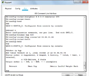
Figura 10. Configuración BGP Router 4
28 Figura 11. Estado de Configuración R3
Figura 12. Estado de Configuración Router 4
Ahora probamos la conexión establecida:
29 Figura 14. Prueba de Configuración Router 4
30
Escenario 3 Figura 15. Escenario 3
A. Configurar VTP
1. Todos los switches se configurarán para usar VTP para las actualizaciones de VLAN. El switch SWT2 se configurará como el servidor. Los switches SWT1 y SWT3 se configurarán como clientes. Los switches estarán en el dominio VPT llamado CCNP y usando la contraseña cisco.
SWT1>en SWT1#conf t
Enter configuration commands, one per line. End with CNTL/Z. SWT1(config)#VTP domain CCNP
Changing VTP domain name from NULL to CCNP. SWT1(config)#vtp mode client
Service device to VTP CLIENT mode SWT1(config)#vtp password cisco
31 SWT2>en
SWT2#configure terminal
Enter configuration commands, one per line. End with CNTL/Z. SWT2(config)#vtp mode server
Device mode already VTP SERVER. SWT2(config)#vtp domain CCNP
Domain name already set to CCNP. SWT2(config)#vtp password cisco
Setting device VLAN database password to cisco SWT2(config)#
SWT3>en SWT3#conf t
Enter configuration commands, one per line. End with CNTL/Z. SWT3(config)#VTP domain CCNP
Changing VTP domain name from NULL to CCNP.
SWT3(config)#vtp mode client
Setting device to VTP CLIENT mode.
SWT3(config)#vtp password cisco
Setting device VLAN database password to cisco SWT3(config)#
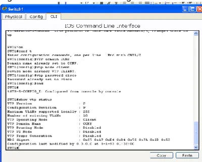
2. Verifique las configuraciones mediante el comando show vtp status.
Figura 16. Verificación de Configuración Switch 1
32
Figura 17. Verificación de Configuración Switch 2
Figura 18 Verificación de Configuración Switch 3
33
B. Configurar DTP (Dynamic Trunking Protocol)
1. Configure un enlace troncal ("trunk") dinámico entre SWT1 y SWT2. Debido a que el modo por defecto es dynamic auto, solo un lado del enlace debe configurarse como dynamic desirable.
SWT1#conf t
Enter configuration commands, one per line. End with CNTL/Z. SWT1(config)#
SWT1(config)#int fa0/1
SWT1(config-if)#switchport mode dynamic desirable
SWT1(config-if)#
%LINEPROTO-5-UPDOWN: Line protocol on Interface FastEthernet0/1, changed state to up
SWT1(config-if)#exit SWT1(config)#end SWT1#
%SYS-5-CONFIG_I: Configured from console by console
2. Verifique el enlace "trunk" entre SWT1 y SWT2 usando el comando show interfaces trunk.
34
3. Entre SWT1 y SWT3 configure un enlace "trunk" estático utilizando el comando switchport mode trunk en la interfaz F0/3 de SWT1
SWT1#conf t
Enter configuration commands, one per line. End with CNTL/Z. SWT1(config)#int fa0/3
SWT1(config-if)#switchport mode trunk SWT1(config-if)#
%LINE PROTO-5-UPDOWN:Line protocol on interface FastEthernet0/3, changed
state to down
%LINE PROTO-5-UPDOWN: Line protocol on interface Fastethernet0/3, changed
state to up
SWT1(config-if)#exit SWT1(config)#end SWT1#
%SYS-5-CONFIG_I: Configured from console by console
4. Verifique el enlace "trunk" el comando show interfaces trunk en SWT1.
35
5. Configure un enlace "trunk" permanente entre SWT2 y SWT3.
SWT2#conf t
Enter configuration commands, one per line. End with CNTL/Z. SWT2(config)#int fa0/3
SWT2(config-if)#switchport mode trunk SWT2(config-if)#
%LINE PROTO-5-UPDOWN:Line protocol on interface FastEthernet0/3, changed
state to down
%LINE PROTO-5-UPDOWN: Line protocol on interface Fastethernet0/3, changed
state to up
SWT2(config-if)#exit SWT2(config)#end SWT2#
%SYS-5-CONFIG_I: Configured from console by console
Figura 21. Configuración enlace "trunk" permanente entre SWT2 y SWT3
C. Agregar VLANs y asignar puertos.
1. En STW1 agregue la VLAN 10. En STW2 agregue las VLANS Compras (10), Mercadeo (20), Planta (30) y Admon (99)
36
Enter configuration commands, one per line. End with CNTL/Z. SWT1(config)#int fa0/10
SWT1(config-if)#sw access vlan 10 SWT1(config-if)#exit
SWT1(config)#end
%SYS-5-CONFIG_I: Configured from console by console SWT2#conf t
Enter configuration commands, one per line. End with CNTL/Z. SWT2(config)#vlan 10
SWT2(config-vlan)#name VLAN_compras SWT2(config-vlan)#vlan 20
SWT2(config-vlan)#name VLAN_Mercadeo
SWT2(config-vlan)#vlan 30 SWT2(config-vlan)#exit
SWT2(config)#vlan 30
SWT2(config-vlan)#name VLAN_Planta
SWT2(config-vlan)#exit SWT2(config)#vlan 99
SWT2(config-vlan)#name VLAN_Admon SWT2(config-vlan)#exit
SWT2(config)#end
%SYS-5-CONFIG_I: Configured from console by console
2. Verifique que las VLANs han sido agregadas correctamente.
37
Asocie los puertos a las VLAN y configure las direcciones IP de acuerdo con la siguiente tabla.
Tabla # 2 Direcciones IP de los PCs
Interfaz VLAN Direcciones IP de los PCs F0/10 VLAN 10 190.108.10.X / 24
F0/15 VLAN 20 190.108.20.X /24 F0/20 VLAN 30 190.108.30.X /24
X = número de cada PC particular
4. Configure el puerto F0/10 en modo de acceso para SWT1, SWT2 y SWT3 y asígnelo a la VLAN 10.
5. Repita el procedimiento para los puertos F0/15 y F0/20 en SWT1, SWT2 y SWT3. Asigne las VLANs y las direcciones IP de los PCs de acuerdo con la tabla de arriba.
SWT1#conf t
Enter configuration commands, one per line. End with CNTL/Z. SWT1(config)#int fa0/10
SWT1(config-if)#switchport mode access SWT1(config-if)#switchport access vlan 10 SWT1(config-if)#exit
SWT1(config)#int fa0/15
SWT1(config-if)#switchport mode access SWT1(config-if)#switchport access vlan 20 SWT1(config-if)#exit
SWT1(config)#int fa0/20
SWT1(config-if)#switchport mode access SWT1(config-if)#switchport access vlan 30 SWT1(config-if)#exit
SWT1(config)#end SWT1#
38 Figura 23. Configuración Planta (PC0):
Figura 24. Configuración Mercadeo (PC1):
Figura 25. Copnfiguración Compras (PC2):
SWT2#conf t
Enter configuration commands, one per line. End with CNTL/Z. SWT2(config)#int fa0/10
SWT2(config-if)#switchport mode access SWT2(config-if)#switchport access vlan 10 SWT2(config-if)#exit
SWT2(config)#int fa0/15
SWT2(config-if)#switchport mode access SWT2(config-if)#switchport access vlan 20 SWT2(config-if)#exit
SWT2(config)#int fa0/20
39 SWT2(config-if)#switchport access vlan 30 SWT2(config-if)#exit
SWT2(config)#end SWT2#
%SYS-5-CONFIG_I: Configured from console by console
Figura 26. Configuración IP Planta (PC5):
Figura 27. Configuración IP Mercadeo (PC4):
40 SWT3#conf t
Enter configuration commands, one per line. End with CNTL/Z. SWT3(config)#int fa0/10
SWT3(config-if)#switchport mode access SWT3(config-if)#switchport access vlan 10 SWT3(config-if)#exit
SWT3(config)#int fa0/15
SWT3(config-if)#switchport mode access SWT3(config-if)#switchport access vlan 20 SWT3(config-if)#exit
SWT3(config)#int fa0/20
SWT3(config-if)#switchport mode access SWT3(config-if)#switchport access vlan 30 SWT3(config-if)#exit
SWT3(config)#end SWT3#
%SYS-5-CONFIG_I: Configured from console by console Figura 29. Configuración IP Planta (PC8):
41 Figura 31. Configuración IP Compras (PC6):
D. Configurar las direcciones IP en los Switches.
1. En cada uno de los Switches asigne una dirección IP al SVI (Switch Virtual Interface) para VLAN 99 de acuerdo con la siguiente tabla de direccionamiento y active la interfaz.
Tabla # 3 Configuraciones SWT1, SWT2 y SWT3
Equipo Interfaz Dirección IP Máscara SWT1 VLAN 99 190.108.99.1 255.255.255.0 SWT2 VLAN 99 190.108.99.2 255.255.255.0
SWT3 VLAN 99 190.108.99.3 255.255.255.0
SWT1>en SWT1#conf t
Enter configuration commands, one per line. End with CNTL/Z. SWT1(config)#int vlan 99
%LINK-5-CHANGED:Interface Vlan99, changed state to up
%LINEPROTO-5-UPDOWN:Line protocol on interface Vlan99, changed state to up
SWT1(config-if)#ip address 190.108.99.1 255.255.255.0 SWT1(config-if)#no shutdown
42
%SYS-5-CONFIG_I: Configured from console by console SWT2>en
SWT2#conf t
Enter configuration commands, one per line. End with CNTL/Z. SWT2(config)#int vlan 99
%LINK-5-CHANGED:Interface Vlan99, changed state to up
%LINEPROTO-5-UPDOWN:Line protocol on interface Vlan99, changed state to up
SWT2(config-if)#ip address 190.108.99.1 255.255.255.0 SWT2(config-if)#no shutdown
SWT2(config-if)#exit SWT2(config)#end SWT2#
%SYS-5-CONFIG_I: Configured from console by console SWT3>en
SWT3#conf t
Enter configuration commands, one per line. End with CNTL/Z. SWT3(config)#int vlan 99
%LINK-5-CHANGED:Interface Vlan99, changed state to up
%LINEPROTO-5-UPDOWN:Line protocol on interface Vlan99, changed state to up
SWT3(config-if)#ip address 190.108.99.1 255.255.255.0 SWT3(config-if)#no shutdown
SWT3(config-if)#exit SWT3(config)#end SWT3#
%SYS-5-CONFIG_I: Configured from console by console E. Verificar la conectividad Extremo a Extremo
43 Figura 32. Ejecución Ping PCO
R/= No tuvo éxito
2. Ejecute un Ping desde cada Switch a los demás. Explique por qué el ping tuvo o no tuvo éxito.
Figura 33. Ejecución Ping desde Switch 2
44
3. Ejecute un Ping desde cada Switch a cada PC. Explique por qué el ping tuvo o no tuvo éxito.
Figura 34. Ejecución Ping de Switch a PC
45
CONCLUSIONES
Se logró dar solución a cada uno de los escenarios planteados por la guía de prueba de habilidades prácticas, con el cual logramos identificar el alcance de las habilidades y competencias que adquirimos en el transcurso del curso, trabajando con protocolos de enrutamiento avanzado, configurando sistemas de redes
soportados en VLANs, administrando y escalando las redes conmutadas, aplicando diferentes formas de configuración de redes.
Se logró comprender, analizar y desarrollar las diferentes situaciones planteadas, aplicando los diferentes temas estudiados en el curso de profundización,
realizando procesos de configuración de protocolos para interfaces Loopback y router, estableciendo dominios y contraseñas predeterminados.
Se aprendió a asignar direcciones ip y configuraciones OSPF y EIGRP,
46
BIBLIOGRAFÍA
Froom, R., Frahim, E. (2015). CISCO Press (Ed). First Hop Redundancy Protocols. Implementing Cisco IP Switched Networks (SWITCH) Foundation Learning Guide CCNP SWITCH Recuperado
dehttps://1drv.ms/b/s!AmIJYei-NT1IlnWR0hoMxgBNv1CJ
Amberg, E. (2014). CCNA 1 Powertraining : ICND1/CCENT (100-101). Heidleberg: MITP. Recuperado
dehttp://bibliotecavirtual.unad.edu.co:2051/login.aspx?direct=true&db=e000xww&A
N=979032&lang=es&site=ehost-live
Lucas, M. (2009). Cisco Routers for the Desperate : Router and Switch Management, the Easy Way. San Francisco: No Starch Press. Recuperado
de http://bibliotecavirtual.unad.edu.co:2051/login.aspx?direct=true&db=e000xww&
AN=440032&lang=es&site=ehost-live
Odom, W. (2013). CISCO Press (Ed). CCNA ICND1 Official Exam Certification Guide. Recuperado
dehttp://ptgmedia.pearsoncmg.com/images/9781587205804/samplepages/978158
7205804.pdf
Odom, W. (2013). CISCO Press (Ed). CCNA ICND2 Official Exam Certification Guide. Recuperado
dehttp://een.iust.ac.ir/profs/Beheshti/Computer%20networking/Auxilary%20materia
ls/Cisco-ICND2.pdf
Lammle, T. (2010). CISCO Press (Ed). Cisco Certified Network Associate Study Guide. Recuperado
dehttp://www.birminghamcharter.com/ourpages/auto/2012/3/22/41980164/C
Teare, D., Vachon B., Graziani, R. (2015). CISCO Press (Ed). Implementing Routing Facilities for Branch Offices and Mobile Workers. Implementing Cisco IP Routing (ROUTE) Foundation Learning Guide CCNP ROUTE. Recuperado de https://1drv.ms/b/s!AmIJYei-NT1IlnMfy2rhPZHwEoWx
Macfarlane, J. (2014). Network Routing Basics : Understanding IP Routing in Cisco Systems. Recuperado