DIPLOMADO DE PROFUNDIZACION CISCO PRUEBA DE HABILIDADES PRÁCTICAS CCNP
YESID FERNEY LOZANO SUELTA
UNIVERSIDAD NACIONAL ABIERTA Y A DISTANCIA – UNAD ESCUELA DE CIENCIAS BÁSICAS, TECNOLOGÍA E INGENIERÍA
INGENIERÍA DE TELECOMUNICACIONES SOGAMOSO – BOYACÁ
DIPLOMADO DE PROFUNDIZACION CISCO PRUEBA DE HABILIDADES PRÁCTICAS CCNP
YESID FERNEY LOZANO SUELTA
Diplomado de opción de grado presentado para optar el título de INGENIERO EN
TELECOMUNICACIONES
DIRECTOR:
MSc. GERARDO GRANADOS ACUÑA
UNIVERSIDAD NACIONAL ABIERTA Y A DISTANCIA – UNAD ESCUELA DE CIENCIAS BÁSICAS, TECNOLOGÍA E INGENIERÍA
INGENIERÍA DE TELECOMUNICACIONES SOGAMOSO – BOYACÁ
3
NOTA DE ACEPTACIÓN
Firma del Presidente del Jurado
Firma del Jurado
Firma del Jurado
4
AGRADECIMIENTOS
5 CONTENIDO
AGRADECIMIENTOS ... 4
CONTENIDO ... 5
LISTA DE TABLAS ... 6
LISTA DE FIGURAS ... 7
RESUMEN ... 9
ABSTRACT ... 9
INTRODUCCIÓN ... 10
DESARROLLO ... 11
1. Escenario 1 ... 11
2. Escenario 2 ... 24
CONCLUSIONES ... 54
6
LISTA DE TABLAS
Tabla 1 Configuración de interfaces ... 14
Tabla 2 Ajuste de banda y DCE ... 15
Tabla 3 Configuración OSPF ... 16
Tabla 4 Configuración area 0 ... 16
Tabla 5 Configuración OPsf área 0 ... 17
Tabla 6 Configuración básica de red ... 27
Tabla 7 Configuración VLAN 800 y demás aplicaciones ... 36
Tabla 8 Servidor principal VLAN ... 37
Tabla 9 Puertos de acceso VLAN ... 39
8
LISTA DE FIGURAS
Ilustración 1 Simulación escenario 1 Packet tracer ... 11
Ilustración 2 Grafico de referencia escenario 1 y topología de Red ... 11
Ilustración 3 Configuración R2 área Stubby ... 17
Ilustración 4 Configuración rutas por defecto IPV4 IPV6 R3 ... 17
Ilustración 5 Configuración interfaces pasivas EIGRP R1 ... 18
Ilustración 6 Configuración redistribución mutua OSPF - EIGRP ... 18
Ilustración 7 Configuración publicidad ruta ACL... 19
Ilustración 8 Verificación IPV6 R1 ... 20
Ilustración 9 Verificación ip route R1 ... 21
Ilustración 10Verificación ip route R2 ... 21
Ilustración 11 Verificación ip route R2 ... 22
Ilustración 12 Verificación ip route R3 ... 22
Ilustración 13Verificación IPV6 R3 ... 23
Ilustración 14 verificación de configuración IPV6 R1y comando ping ... 23
Ilustración 15 Verificación lista de acceso R2 ... 24
Ilustración 16 Verificación comando ping R2 ... 24
Ilustración 17 Verificación de configuración IPV6 R3 ... 25
Ilustración 18 Grafico de referencia escenario 2 y topología de Red ... 26
Ilustración 19 Simulación Escenario 2 - Packet tracer ... 26
Ilustración 20 Ilustración 1 Configuración LACP interfaces 11-12 DLS1 ... 27
Ilustración 21 Configuración LACP interfaces 11-12 DLS2 ... 28
Ilustración 22 Configuración LACP interfaces 7-8 ... 28
Ilustración 23 Configuración PAgP DLS1 ... 29
Ilustración 24 Configuración PAgP ALS2 ... 29
Ilustración 25 Configuración PAgP DLS2 ... 29
Ilustración 26 Configuración PAgP ALS1 ... 30
Ilustración 27 Configuración puertos troncales VLAN 800 nativa ... 30
Ilustración 28 Configuración de Dominio y contraseña ... 36
Ilustración 29 Configuración para poner DLS1 como servidor ... 36
Ilustración 30 Configuración para suspender VLAN 434 DLS1 ... 37
9
Ilustración 32 Configuración para suspender VLAN 434 ... 38
Ilustración 33 Configuración de nueva VLAN ... 38
Ilustración 34 Configuración DLS1 spanning tree root ... 38
Ilustración 35 Configuraciòn Spanning tree root DLS2 ... 38
Ilustración 36 Configuración puertos troncales VLAN ... 38
Ilustración 37 Configuración de interfaces puerto de acceso DLS1 ... 39
Ilustración 38 Configuración de interfaces puerto de acceso DLS2 ... 40
Ilustración 39 Configuración de interfaces puerto de acceso ALS1 ... 40
Ilustración 40 Configuración de interfaces puerto de acceso ALS2 ... 41
Ilustración 41 Visualización VLAN correctas ... 41
Ilustración 42 Visualización VLAN correctas ... 42
Ilustración 43 Verificacion de configuracion DLS1 ... 42
9 RESUMEN
En el siguiente trabajo se abarcan temas tan importantes como la configuración de las redes y los métodos que mas se utilizan para crear, modificar, y realizar enlaces con el uso de diferentes canales en base a la tecnología usada por Cisco junto con sus equipos de red. Teniendo en cuenta lo anterior y en la fase final del curso en CCNP y para probar las habilidades adquiridas es necesario que se desarrollen las dos simulaciones propuestas, con diferentes aspectos para lograr un networking exitoso soportado en la configuración de Vlans, administración y enrutamiento, utilización de protocolos y algo que es muy importante con la introducción de las direcciones IPV6 y cómo utilizarlas en los diferentes escenarios.
Veremos cómo paso a paso se va dando solución a el ejercicio planteado utilizando el software Packet tracer en routers y switchs.
Para conseguir que se cumpla con el objetivo de esta actividad es necesario cumplir con los estándares de calidad establecidos por la Universidad y los conocimientos obtenidos en el transcurso del curso.
Palabras Clave: CISCO, CCNP, REDES, ROUTER, SWITCH, IPV6, NETWORKING.
ABSTRACT
The following work covers topics as important as the configuration of the networks and the methods that are most used to create, modify, and make links with the use of different channels based on the technology used by Cisco together with its network equipment . Taking into account the above and in the final phase of the course in CCNP and to test the acquired skills it is necessary to develop the two simulations proposed, with different aspects to achieve a successful networking supported in the configuration of Vlans, administration and routing, use of protocols and something that is very important with the introduction of IPV6 addresses and how to use them in different scenarios.
We will see how step by step solution is being given to the exercise proposed using the Packet tracer software on routers and switches.
In order to achieve the objective of this activity, it is necessary to comply with the quality standards established by the University and the knowledge obtained during the course.
10 INTRODUCCION
La evolución tecnológica que está atravesando nuestro país y la necesidad de estar a la altura internacional en la solución de networking es en definitiva el primer paso para abordar un cambio en tecnologías de comunicaciones y los canales que se utilizan. Como estudiante de ingeniería de telecomunicaciones y teniendo en cuenta lo antes mencionado tome como objetivo profesional el desarrollo exitoso del curso CCNP como diplomado de profundización.
El siguiente trabajo es la consolidación final de las diferentes actividades propuestas durante el desarrollo del curso de forma colaborativa e individual con el desarrollo de evaluaciones que dejaron en mis conocimientos amplios en temas bases como enrutamiento, vlans, administración y seguridad utilizando el software Packet tracer y realizando configuraciones de modo que se demuestre la exitosa conectividad y se de solución a los problemas planteados.
Para este trabajo se nos calificara con el desarrollo de los escenarios propuestos, para lo cual lo evidencio con imágenes de pantallazos y algunas configuraciones tomados directamente desde la consola de los equipos de red utilizados como lo fueron routers y switchs de la familia Cisco, se verifico su conectividad utilizando comandos show ip route, ping, show vlan, e otros.
11 DESARROLLO
ESCENARIO 1:
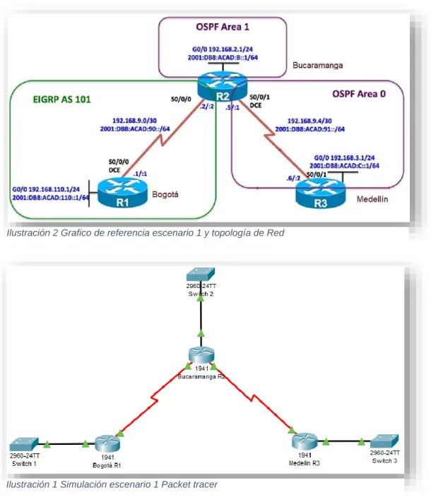
Una empresa de confecciones posee tres sucursales distribuidas en las ciudades de Bogotá, Medellín y Bucaramanga, en donde el estudiante será el administrador de la red, el cual deberá configurar e interconectar entre sí cada uno de los dispositivos que forman parte del escenario, acorde con los lineamientos establecidos para el direccionamiento IP, protocolos de enrutamiento y demás aspectos que forman parte de la topología de red.
Ilustración 1 Simulación escenario 1 Packet tracer
Ilustración 2 Grafico de referencia escenario 1 y topología de Red
Anexo de simulación:
https://unadvirtualedu-my.sharepoint.com/:f:/g/personal/yflozanos_unadvirtual_edu_co/EqUNIUAvigVGrr
12 Parte 1: Configuración del escenario propuesto
1. Configurar las interfaces con las direcciones IPv4 e IPv6 que se muestran en la topología de red.
Configuración de interfaces para cada router: Router 1:
Router#conf te
Enter configuration commands, one per line. End with CNTL/Z. Router(config)#hostname R1
R1(config)#interface s0/0/0
R1(config-if)#ip address 192.168.9.1 255.255.255.252 R1(config-if)#no shut
R1(config-if)#
%LINK-5-CHANGED: Interface Serial0/0/0, changed state to up
R1(config-if)#
%LINEPROTO-5-UPDOWN: Line protocol on Interface Serial0/0/0, changed state to up
R1(config-if)#exit
R1(config)#interface g0/0
R1(config-if)#ip address 192.168.110.1 255.255.255.0 R1(config-if)#no shut
R1(config-if)#
%LINK-5-CHANGED: Interface GigabitEthernet0/0, changed state to up
R1(config-if)#ipv6 unicast-routing R1(config)#ipv6 unicast-routing R1(config)#interface s0/0/0
R1(config-if)#ipv6 address 2001:DB8:ACAD:90::1/64 R1(config-if)#ipv6 address FE80::1 link-local
R1(config-if)#exit R1(config)#exi R1#
Router 2:
Router#conf t
Enter configuration commands, one per line. End with CNTL/Z. Router(config)#hostname R2
13
R2(config-if)#ip address 192.168.9.2 255.255.255.252 R2(config-if)#no shut
%LINK-5-CHANGED: Interface Serial0/0/0, changed state to down R2(config-if)#exit
R2(config)#interface g0/0
R2(config-if)#ip address 192.168.2.1 255.255.255.0 R2(config-if)#no shut
R2(config-if)#
%LINK-5-CHANGED: Interface GigabitEthernet0/0, changed state to up
R2(config-if)#exit
R2(config)#interface s0/0/1
R2(config-if)#ip address 192.168.9.5 255.255.255.252 R2(config-if)#no shut
%LINK-5-CHANGED: Interface Serial0/0/1, changed state to down R2(config-if)#ipv6 unicast-routing
R2(config)#interface s0/0/0
R2(config-if)#ipv6 address 2001:DB8:ACAD:90::2/64 R2(config-if)#ipv6 address FE80::2 link-local
R2(config-if)#no shut R2(config-if)#exit
R2(config)#interface g0/0
R2(config-if)#ipv6 address 2001:DB8:ACAD:8::1/64 R2(config-if)#ipv6 address FE80::2 link-local
R2(config-if)#no shut R2(config-if)#exit
R2(config)#interface s0/0/1
R2(config-if)#ipv6 address 2001:DB8:ACAD:91::1/64 R2(config-if)#no shut
R2(config-if)#exit R2(config)#exit R2#
%SYS-5-CONFIG_I: Configured from console by console
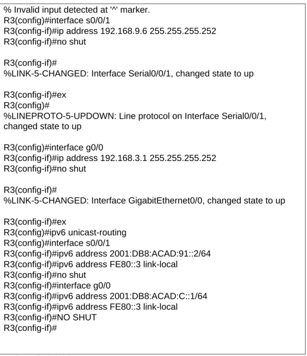
Router 3:
Router>en Router#conf t
Enter configuration commands, one per line. End with CNTL/Z. Router(config)#hostname R3
14 % Invalid input detected at '^' marker. R3(config)#interface s0/0/1
R3(config-if)#ip address 192.168.9.6 255.255.255.252 R3(config-if)#no shut
R3(config-if)#
%LINK-5-CHANGED: Interface Serial0/0/1, changed state to up
R3(config-if)#ex R3(config)#
%LINEPROTO-5-UPDOWN: Line protocol on Interface Serial0/0/1, changed state to up
R3(config)#interface g0/0
R3(config-if)#ip address 192.168.3.1 255.255.255.252 R3(config-if)#no shut
R3(config-if)#
%LINK-5-CHANGED: Interface GigabitEthernet0/0, changed state to up
R3(config-if)#ex
R3(config)#ipv6 unicast-routing R3(config)#interface s0/0/1
R3(config-if)#ipv6 address 2001:DB8:ACAD:91::2/64 R3(config-if)#ipv6 address FE80::3 link-local
R3(config-if)#no shut R3(config-if)#interface g0/0
R3(config-if)#ipv6 address 2001:DB8:ACAD:C::1/64 R3(config-if)#ipv6 address FE80::3 link-local
R3(config-if)#NO SHUT R3(config-if)#
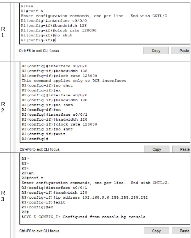
Tabla 1 Configuración de interfaces
15 R
1
R 2
R 3
Tabla 2 Ajuste de banda y DCE
16 R
2
R 3
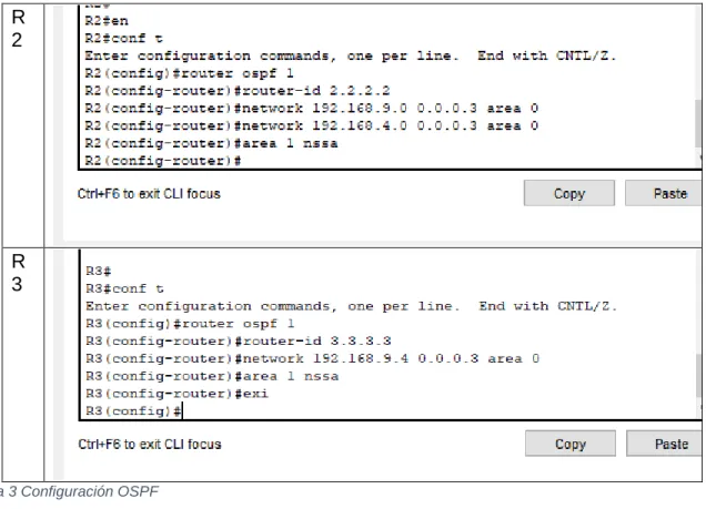
Tabla 3 Configuración OSPF
4. En R2, configurar la interfaz F0/0 en el área 1 de OSPF y la conexión serial entre R2 y R3 en OSPF área 0.
R2: R3:
interface g0/0
ospfv3 1 ipv4 area 1 ospfv3 1 ipv6 area 1 12
exit
interface s0/0/1 ospfv3 1 ipv4 area 0 ospfv3 1 ipv6 area 0 exit
interface g0/0
ospfv3 1 ipv4 area 1 ospfv3 1 ipv6 area 1 exit
interface s0/0/1 ospfv3 1 ipv4 area 0 ospfv3 1 ipv6 area 0 exit
Tabla 4 Configuración area 0
5. En R3, configurar la interfaz F0/0 y la conexión serial entre R2 y R3 en OSPF área 0.
interface g0/0
ospfv3 1 ipv4 area 1 ospfv3 1 ipv6 area 1 exit
17 ospfv3 1 ipv4 area 0
ospfv3 1 ipv6 area 0 exit
Tabla 5 Configuración OPsf área 0
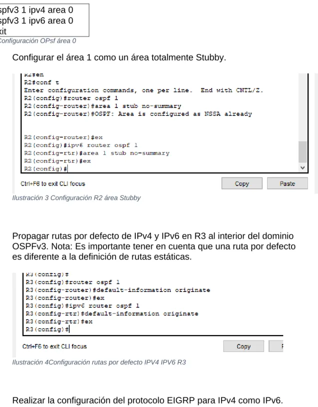
6. Configurar el área 1 como un área totalmente Stubby.
Ilustración 3 Configuración R2 área Stubby
7. Propagar rutas por defecto de IPv4 y IPv6 en R3 al interior del dominio OSPFv3. Nota: Es importante tener en cuenta que una ruta por defecto es diferente a la definición de rutas estáticas.
Ilustración 4Configuración rutas por defecto IPV4 IPV6 R3
18
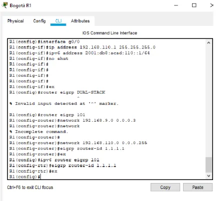
9. Configurar las interfaces pasivas para EIGRP según sea apropiado.
Ilustración 5 Configuración interfaces pasivas EIGRP R1
10. En R2, configurar la redistribución mutua entre OSPF y EIGRP para IPv4 e IPv6. Asignar métricas apropiadas cuando sea necesario.
19
11. En R2, de hacer publicidad de la ruta 192.168.3.0/24 a R1 mediante una lista de distribución y ACL.
20
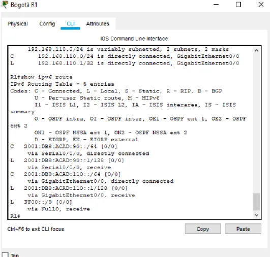
Parte 2: Verificar conectividad de red y control de la trayectoria.
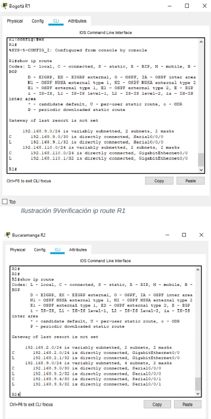
a. Registrar las tablas de enrutamiento en cada uno de los routers, acorde con los parámetros de configuración establecidos en el escenario propuesto.
b. Verificar comunicación entre routers mediante el comando ping y traceroute c. Verificar que las rutas filtradas no están presentes en las tablas de enrutamiento de los routers correctas. Verificar comunicación ping Verificación de rutas filtradas
21
Ilustración 9Verificación ip route R1
22
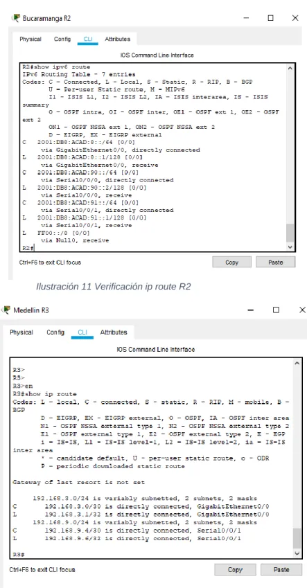
Ilustración 11 Verificación ip route R2
23
Ilustración 13Verificación IPV6 R3
24
Ilustración 15 Verificación lista de acceso R2
25
26 ESCENARIO 2:
Una empresa de comunicaciones presenta una estructura Core acorde a la topología de red, en donde el estudiante será el administrador de la red, el cual deberá configurar e interconectar entre sí cada uno de los dispositivos que forman parte del escenario, acorde con los lineamientos establecidos para el
direccionamiento IP, etherchannels, VLANs y demás aspectos que forman parte del escenario propuesto
Ilustración 18 Simulación Escenario 2 - Packet tracer
Ilustración 19 Grafico de referencia escenario 2 y topología de Red
Anexo de simulación:
https://unadvirtualedu-my.sharepoint.com/:f:/g/personal/yflozanos_unadvirtual_edu_co/EqUNIUAvigVGrr
27
Parte 1: Configurar la red de acuerdo con las especificaciones. a. Apagar todas las interfaces en cada switch.
b. Asignar un nombre a cada switch acorde al escenario establecido.
c. Configurar los puertos troncales y Port-channels tal como se muestra en el diagrama.
DLS1 int ran f0/1-24, g0/1-2 shutdown
exit
DLS2 int ran f0/1-24, g0/1-2 shutdown
exit
ALS1 int ran f0/1-24, g0/1-2 shutdown
exit
ALS2 int ran f0/1-24, g0/1-2 shutdown
exit
Tabla 6 Configuración básica de red
1) La conexión entre DLS1 y DLS2 será un EtherChannel capa-3 utilizando LACP.
Para DLS1 se utilizará la dirección IP 10.12.12.1/30 y para DLS2 utilizará 10.12.12.2/30.
28
Ilustración 21 Configuración LACP interfaces 11-12 DLS2
2) Los Port-channels en las interfaces Fa0/7 y Fa0/8 utilizarán LACP.
Ilustración 22 Configuración LACP interfaces 7-8
29
Ilustración 23 Configuración PAgP DLS1
Ilustración 24 Configuración PAgP ALS2
30
Ilustración 26 Configuración PAgP ALS1
4) Todos los puertos troncales serán asignados a la VLAN 800 como la VLAN nativa.
Ilustración 27 Configuración puertos troncales VLAN 800 nativa
%LINEPROTO-5-UPDOWN: Line protocol on Interface Port-channel1interface range f0/9-10
DLS1(config-if-range)#channel-group 4 mode desirable DLS1(config-if-range)#
Creating a port-channel interface Port-channel 4
DLS1(config-if-range)#no shut
%LINK-5-CHANGED: Interface FastEthernet0/9, changed state to down
31 DLS1(config-if-range)#
%LINK-5-CHANGED: Interface FastEthernet0/9, changed state to up
%LINEPROTO-5-UPDOWN: Line protocol on Interface FastEthernet0/9, changed state to up
%LINK-5-CHANGED: Interface FastEthernet0/10, changed state to up
%LINEPROTO-5-UPDOWN: Line protocol on Interface FastEthernet0/10, changed state to up
%LINK-5-CHANGED: Interface Port-channel4, changed state to up
%LINEPROTO-5-UPDOWN: Line protocol on Interface Port-channel4, changed state to up
DLS1(config-if-range)# DLS1(config-if-range)#ex
DLS1(config)#interface range f0/9-10 DLS1(config-if-range)#ex
DLS1(config)#interface range f0/11-12 DLS1(config-if-range)#no swithport ^
% Invalid input detected at '^' marker. DLS1(config-if-range)#
DLS1(config-if-range)#channel-group 12 mode active DLS1(config-if-range)#
%LINEPROTO-5-UPDOWN: Line protocol on Interface FastEthernet0/11, changed state to down
%LINEPROTO-5-UPDOWN: Line protocol on Interface FastEthernet0/11, changed state to up
%LINK-3-UPDOWN: Interface Port-channel12, changed state to down
%LINEPROTO-5-UPDOWN: Line protocol on Interface Port-channel12, changed state to down
%LINEPROTO-5-UPDOWN: Line protocol on Interface FastEthernet0/12, changed state to down
%LINEPROTO-5-UPDOWN: Line protocol on Interface FastEthernet0/12, changed state to up
32 DLS1(config-if-range)#e
DLS1(config)#interface port-channel 12 DLS1(config-if)#
%LINK-5-CHANGED: Interface Port-channel12, changed state to up
%LINEPROTO-5-UPDOWN: Line protocol on Interface Port-channel12, changed state to up
DLS1(config-if)#ip address 10.12.12.1 255.255.255.252 ^
% Invalid input detected at '^' marker.
DLS1(config-if)#ip address 10.12.12.1 255.255.255.252 ^
% Invalid input detected at '^' marker.
DLS1(config-if)#switchport trunk encapsulation dot1q DLS1(config-if)#switchport trunk native vlan 800 DLS1(config-if)#switchport mode trunk
DLS1(config-if)#switchpo
%CDP-4-NATIVE_VLAN_MISMATCH: Native VLAN mismatch discovered on FastEthernet0/11 (800), with DLS2 FastEthernet0/11 (1).
%CDP-4-NATIVE_VLAN_MISMATCH: Native VLAN mismatch discovered on FastEthernet0/12 (800), with DLS2 FastEthernet0/11 (1).
%CDP-4-NATIVE_VLAN_MISMATCH: Native VLAN mismatch discovered on FastEthernet0/11 (800), with DLS2 FastEthernet0/12 (1).
%CDP-4-NATIVE_VLAN_MISMATCH: Native VLAN mismatch discovered on FastEthernet0/12 (800), with DLS2 FastEthernet0/12 (1).
%CDP-4-NATIVE_VLAN_MISMATCH: Native VLAN mismatch discovered on FastEthernet0/11 (800), with DLS2 Port-channel12 (1).
%CDP-4-NATIVE_VLAN_MISMATCH: Native VLAN mismatch discovered on FastEthernet0/12 (800), with DLS2 Port-channel12 (1).
DLS1(config-if)#switchport nonegotiate DLS1(config-if)#
%CDP-4-NATIVE_VLAN_MISMATCH: Native VLAN mismatch discovered on FastEthernet0/11 (800), with DLS2 FastEthernet0/11 (1).
33
%CDP-4-NATIVE_VLAN_MISMATCH: Native VLAN mismatch discovered on FastEthernet0/11 (800), with DLS2 FastEthernet0/12 (1).
%CDP-4-NATIVE_VLAN_MISMATCH: Native VLAN mismatch discovered on FastEthernet0/12 (800), with DLS2 FastEthernet0/12 (1).
%CDP-4-NATIVE_VLAN_MISMATCH: Native VLAN mismatch discovered on FastEthernet0/11 (800), with DLS2 Port-channel12 (1).
%CDP-4-NATIVE_VLAN_MISMATCH: Native VLAN mismatch discovered on FastEthernet0/12 (800), with DLS2 Port-channel12 (1).
DLS1(config-if)#no shut DLS1(config-if)#ex
DLS1(config)#interface interface range f0/7-8 ^
% Invalid input detected at '^' marker. DLS1(config)#
%CDP-4-NATIVE_VLAN_MISMATCH: Native VLAN mismatch discovered on FastEthernet0/11 (800), with DLS2 FastEthernet0/11 (1).
%CDP-4-NATIVE_VLAN_MISMATCH: Native VLAN mismatch discovered on FastEthernet0/12 (800), with DLS2 FastEthernet0/11 (1).
%CDP-4-NATIVE_VLAN_MISMATCH: Native VLAN mismatch discovered on FastEthernet0/11 (800), with DLS2 FastEthernet0/12 (1).
%CDP-4-NATIVE_VLAN_MISMATCH: Native VLAN mismatch discovered on FastEthernet0/12 (800), with DLS2 FastEthernet0/12 (1).
%CDP-4-NATIVE_VLAN_MISMATCH: Native VLAN mismatch discovered on FastEthernet0/11 (800), with DLS2 Port-channel12 (1).
%CDP-4-NATIVE_VLAN_MISMATCH: Native VLAN mismatch discovered on FastEthernet0/12 (800), with DLS2 Port-channel12 (1).
DLS1(config)#interface interface range f0/7-8 ^
% Invalid input detected at '^' marker. DLS1(config)#interface range f0/7-8
DLS1(config-if-range)#desc member of po1
%CDP-4-NATIVE_VLAN_MISMATCH: Native VLAN mismatch discovered on FastEthernet0/11 (800), with DLS2 FastEthernet0/11 (1).
34
FastEthernet0/12 (800), with DLS2 FastEthernet0/11 (1).
%CDP-4-NATIVE_VLAN_MISMATCH: Native VLAN mismatch discovered on FastEthernet0/11 (800), with DLS2 FastEthernet0/12 (1).
%CDP-4-NATIVE_VLAN_MISMATCH: Native VLAN mismatch discovered on FastEthernet0/12 (800), with DLS2 FastEthernet0/12 (1).
%CDP-4-NATIVE_VLAN_MISMATCH: Native VLAN mismatch discovered on FastEthernet0/11 (800), with DLS2 Port-channel12 (1).
%CDP-4-NATIVE_VLAN_MISMATCH: Native VLAN mismatch discovered on FastEthernet0/12 (800), with DLS2 Port-channel12 (1).
DLS1(config-if-range)#desc member of po1 to als1 DLS1(config-if-range)#channel-group 1 mode active DLS1(config-if-range)#
%LINEPROTO-5-UPDOWN: Line protocol on Interface FastEthernet0/7, changed state to down
%LINEPROTO-5-UPDOWN: Line protocol on Interface FastEthernet0/7, changed state to up
%LINK-3-UPDOWN: Interface Port-channel1, changed state to down
%LINEPROTO-5-UPDOWN: Line protocol on Interface Port-channel1, changed state to down
%LINEPROTO-5-UPDOWN: Line protocol on Interface FastEthernet0/8, changed state to down
%LINEPROTO-5-UPDOWN: Line protocol on Interface FastEthernet0/8, changed state to up
DLS1(config-if-range)#ex
DLS1(config)#interface range f0/9-10
DLS1(config-if-range)#desc member of po4 to als1
%CDP-4-NATIVE_VLAN_MISMATCH: Native VLAN mismatch discovered on FastEthernet0/11 (800), with DLS2 FastEthernet0/11 (1).
%CDP-4-NATIVE_VLAN_MISMATCH: Native VLAN mismatch discovered on FastEthernet0/12 (800), with DLS2 FastEthernet0/11 (1).
35
%CDP-4-NATIVE_VLAN_MISMATCH: Native VLAN mismatch discovered on FastEthernet0/12 (800), with DLS2 FastEthernet0/12 (1).
%CDP-4-NATIVE_VLAN_MISMATCH: Native VLAN mismatch discovered on FastEthernet0/11 (800), with DLS2 Port-channel12 (1).
%CDP-4-NATIVE_VLAN_MISMATCH: Native VLAN mismatch discovered on FastEthernet0/12 (800), withdesc member of po1 to als1
DLS1(config-if-range)#desc member of po1 to als1
%LINK-5-CHANGED: Interface Port-channel1, changed state to up
%LINEPROTO-5-UPDOWN: Line protocol on Interface Port-chaninterface range f0/9-10
DLS1(config-if-range)#desc member of po4 to als2 DLS1(config-if-range)#channel-group 4 mode desirable DLS1(config-if-range)#
%LINK-3-UPDOWN: Interface Port-channel4, changed state to down
%LINEPROTO-5-UPDOWN: Line protocol on Interface Port-channel4, changed state to down
DLS1(config-if-range)#ex DLS1(config)#
%LINK-5-CHANGED: Interface Port-channel4, changed state to up
%LINEPROTO-5-UPDOWN: Line protocol on Interface Port-channel4, changed state to up
%CDP-4-NATIVE_VLAN_MISMATCH: Native VLAN mismatch discovered on FastEthernet0/11 (800), with DLS2 FastEthernet0/11 (1).
%CDP-4-NATIVE_VLAN_MISMATCH: Native VLAN mismatch discovered on FastEthernet0/12 (800), with DLS2 FastEthernet0/11 (1).
%CDP-4-NATIVE_VLAN_MISMATCH: Native VLAN mismatch discovered on FastEthernet0/11 (800), with DLS2 FastEthernet0/12 (1).
%CDP-4-NATIVE_VLAN_MISMATCH: Native VLAN mismatch discovered on FastEthernet0/12 (800), with DLS2 FastEthernet0/12 (1).
%CDP-4-NATIVE_VLAN_MISMATCH: Native VLAN mismatch discovered on FastEthernet0/11 (800), with DLS2 Port-channel12 (1).
36
FastEthernet0/12 (800), with DLS2 Port-channel12 (1).
%CDP-4-NATIVE_VLAN_MISMATCH: Native VLAN mismatch discovered on FastEthernet0/11 (800), with DLS2 FastEthernet0/11 (1).
%CDP-4-NATIVE_VLAN_MISMATCH: Native VLAN mismatch discovered on FastEthernet0/12 (800), with DLS2 FastEthernet0/11 (1).
%CDP-4-NATIVE_VLAN_MISMATCH: Native VLAN mismatch discovered on FastEthernet0/11 (800), with DLS2 FastEthernet0/12 (1).
%CDP-4-NATIVE_VLAN_MISMATCH: Native VLAN mismatch discovered on FastEthernet0/12 (800), with DLS2 FastEthernet0/12 (1).
%CDP-4-NATIVE_VLAN_MISMATCH: Native VLAN mismatch discovered on FastEthernet0/11 (800), with DLS2 Port-channel12 (1).
%CDP-4-NATIVE_VLAN_MISMATCH: Native VLAN mismatch discovered on FastEthernet0/12 (800), with DLS2 Port-channel12 (1).
Tabla 7 Configuración VLAN 800 y demás aplicaciones
d. Configurar DLS1, ALS1, y ALS2 para utilizar VTP versión 3
1) Utilizar el nombre de dominio UNAD con la contraseña cisco123
Ilustración 28 Configuración de Dominio y contraseña
2) Configurar DLS1 como servidor principal para las VLAN.
37
3) Configurar ALS1 y ALS2 como clientes VTP.
e. Configurar en el servidor principal las siguientes VLAN:
f. En DLS1, suspender la VLAN 434.
Ilustración 30 Configuración para suspender VLAN 434 DLS1
g. Configurar DLS2 en modo VTP transparente VTP utilizando VTP versión 2, y configurar en DLS2 las mismas VLAN que en DLS1.
Ilustración 31 Configuración DLS2 modo VTP
Número de VLAN
Nombre de VLAN
Número de VLAN
Nombre de VLAN
800 NATIVA 434 ESTACIONAMIENTO
12 EJECUTIVOS 123 MANTENIMIENTO
234 HUESPEDES 1010 VOZ
11 11
VIDEONET 3456 ADMINISTRACIÓN
38
h. Suspender VLAN 434 en DLS2.
Ilustración 32 Configuración para suspender VLAN 434
i. En DLS2, crear VLAN 567 con el nombre de CONTABILIDAD. La VLAN
de CONTABILIDAD no podrá estar disponible en cualquier otro Switch de la red.
Ilustración 33 Configuración de nueva VLAN
j. Configurar DLS1 como Spanning tree root para las VLAN 1, 12, 434, 800, 1010, 1111 y 3456 y como raíz secundaria para las VLAN 123 y 234.
Ilustración 34 configuración DLS1 spanning tree root
k. Configurar DLS2 como Spanning tree root para las VLAN 123 y 234 y como una raíz secundaria para las VLAN 12, 434, 800, 1010, 1111 y 3456.
Ilustración 35Configuraciòn Spanning tree root DLS2
l. Configurar todos los puertos como troncales de tal forma que solamente las VLAN que se han creado se les permitirá circular a través de éstos puertos.
39
m. Configurar las siguientes interfaces como puertos de acceso, asignados a las VLAN de la siguiente manera:
Interfaz DL
S1
DLS2 ALS1 AL
S2
Interfaz Fa0/6 34
56
12 , 1010
123, 1010
23 4
Interfaz Fa0/15 11 11
1111 1111 1
1 1 1
Interfaces F0 /16-18 567
Tabla 9 Puertos de acceso VLAN
40
Ilustración 38configuración de interfaces puerto de acceso DLS2
41
Ilustración 40 configuración de interfaces puerto de acceso ALS2
Parte 2: conectividad de red de prueba y las opciones configuradas.
a. Verificar la existencia de las VLAN correctas en todos los switches y la asignación de puertos troncales y de acceso
42
Ilustración 42 visualización VLAN correctas
b. Verificar que el EtherChannel entre DLS1 y ALS1 está configurado correctamente
43
Ilustración 44 verificación configuración
c. Verificar la configuración de Spanning tree entre DLS1 o DLS2 para cada VLAN.
DLS1>show spanning-tree VLAN0001
Spanning tree enabled protocol ieee Root ID Priority 24577
Address 00D0.BC21.EAC6 This bridge is the root
Hello Time 2 sec Max Age 20 sec Forward Delay 15 sec
Bridge ID Priority 24577 (priority 24576 sys-id-ext 1) Address 00D0.BC21.EAC6
Hello Time 2 sec Max Age 20 sec Forward Delay 15 sec Aging Time 20
Interface Role Sts Cost Prio.Nbr Type
--- ---- --- --- --- --- Fa0/11 Desg FWD 19 128.11 P2p
Fa0/12 Desg FWD 19 128.12 P2p Fa0/7 Desg FWD 19 128.7 P2p Fa0/8 Desg FWD 19 128.8 P2p
Po4 Desg BKN*9 128.28 Shr *TYPE_Inc
VLAN0012
44 Address 00D0.BC21.EAC6
This bridge is the root
Hello Time 2 sec Max Age 20 sec Forward Delay 15 sec
Bridge ID Priority 24588 (priority 24576 sys-id-ext 12) Address 00D0.BC21.EAC6
Hello Time 2 sec Max Age 20 sec Forward Delay 15 sec Aging Time 20
Interface Role Sts Cost Prio.Nbr Type
--- ---- --- --- --- --- Fa0/11 Desg FWD 19 128.11 P2p
Fa0/12 Desg FWD 19 128.12 P2p Fa0/7 Desg FWD 19 128.7 P2p Fa0/8 Desg FWD 19 128.8 P2p
VLAN0123
Spanning tree enabled protocol ieee Root ID Priority 28795
Address 00D0.BC21.EAC6 This bridge is the root
Hello Time 2 sec Max Age 20 sec Forward Delay 15 sec
Bridge ID Priority 28795 (priority 28672 sys-id-ext 123) Address 00D0.BC21.EAC6
Hello Time 2 sec Max Age 20 sec Forward Delay 15 sec Aging Time 20
Interface Role Sts Cost Prio.Nbr Type
--- ---- --- --- --- --- Fa0/11 Desg FWD 19 128.11 P2p
Fa0/12 Desg FWD 19 128.12 P2p Fa0/7 Desg FWD 19 128.7 P2p Fa0/8 Desg FWD 19 128.8 P2p
VLAN0234
Spanning tree enabled protocol ieee Root ID Priority 28906
Address 00D0.BC21.EAC6 This bridge is the root
Hello Time 2 sec Max Age 20 sec Forward Delay 15 sec
Bridge ID Priority 28906 (priority 28672 sys-id-ext 234) Address 00D0.BC21.EAC6
45 Aging Time 20
Interface Role Sts Cost Prio.Nbr Type
--- ---- --- --- --- --- Fa0/11 Desg FWD 19 128.11 P2p
Fa0/12 Desg FWD 19 128.12 P2p Fa0/7 Desg FWD 19 128.7 P2p Fa0/8 Desg FWD 19 128.8 P2p
VLAN0434
Spanning tree enabled protocol ieee Root ID Priority 25010
Address 00D0.BC21.EAC6 This bridge is the root
Hello Time 2 sec Max Age 20 sec Forward Delay 15 sec
Bridge ID Priority 25010 (priority 24576 sys-id-ext 434) Address 00D0.BC21.EAC6
Hello Time 2 sec Max Age 20 sec Forward Delay 15 sec Aging Time 20
Interface Role Sts Cost Prio.Nbr Type
--- ---- --- --- --- --- Fa0/11 Desg FWD 19 128.11 P2p
Fa0/12 Desg FWD 19 128.12 P2p Fa0/7 Desg FWD 19 128.7 P2p Fa0/8 Desg FWD 19 128.8 P2p
VLAN0800
Spanning tree enabled protocol ieee Root ID Priority 25376
Address 00D0.BC21.EAC6 This bridge is the root
Hello Time 2 sec Max Age 20 sec Forward Delay 15 sec
Bridge ID Priority 25376 (priority 24576 sys-id-ext 800) Address 00D0.BC21.EAC6
Hello Time 2 sec Max Age 20 sec Forward Delay 15 sec Aging Time 20
Interface Role Sts Cost Prio.Nbr Type
--- ---- --- --- --- --- Fa0/11 Desg FWD 19 128.11 P2p
46 Fa0/8 Altn BLK 19 128.8 P2p
Tabla 10 Verificacion Spanning tree DLS1 Y DLS2
DLS2>
DLS2>show spanning-tree VLAN0001
Spanning tree enabled protocol ieee Root ID Priority 24577
Address 00D0.BC21.EAC6 Cost 18
Port 27(Port-channel2)
Hello Time 2 sec Max Age 20 sec Forward Delay 15 sec
Bridge ID Priority 32769 (priority 32768 sys-id-ext 1) Address 0060.70A1.24BA
Hello Time 2 sec Max Age 20 sec Forward Delay 15 sec Aging Time 20
Interface Role Sts Cost Prio.Nbr Type
--- ---- --- --- --- --- Fa0/12 Altn BLK 19 128.12 P2p
Fa0/11 Altn BLK 19 128.11 P2p Po2 Root FWD 9 128.27 Shr Po3 Desg FWD 9 128.28 Shr
VLAN0012
Spanning tree enabled protocol ieee Root ID Priority 28684
Address 0060.70A1.24BA This bridge is the root
Hello Time 2 sec Max Age 20 sec Forward Delay 15 sec
Bridge ID Priority 28684 (priority 28672 sys-id-ext 12) Address 0060.70A1.24BA
Hello Time 2 sec Max Age 20 sec Forward Delay 15 sec Aging Time 20
Interface Role Sts Cost Prio.Nbr Type
--- ---- --- --- --- --- Fa0/6 Desg FWD 19 128.6 P2p
Po2 Desg FWD 9 128.27 Shr Po3 Desg FWD 9 128.28 Shr
VLAN0123
Spanning tree enabled protocol ieee Root ID Priority 24699
47 This bridge is the root
Hello Time 2 sec Max Age 20 sec Forward Delay 15 sec
Bridge ID Priority 24699 (priority 24576 sys-id-ext 123) Address 0060.70A1.24BA
Hello Time 2 sec Max Age 20 sec Forward Delay 15 sec Aging Time 20
Interface Role Sts Cost Prio.Nbr Type
--- ---- --- --- --- --- Po2 Desg FWD 9 128.27 Shr
Po3 Desg FWD 9 128.28 Shr
VLAN0234
Spanning tree enabled protocol ieee Root ID Priority 24810
Address 0060.70A1.24BA This bridge is the root
Hello Time 2 sec Max Age 20 sec Forward Delay 15 sec
Bridge ID Priority 24810 (priority 24576 sys-id-ext 234) Address 0060.70A1.24BA
Hello Time 2 sec Max Age 20 sec Forward Delay 15 sec Aging Time 20
Interface Role Sts Cost Prio.Nbr Type
--- ---- --- --- --- --- Po2 Desg FWD 9 128.27 Shr
Po3 Desg FWD 9 128.28 Shr
VLAN0434
Spanning tree enabled protocol ieee Root ID Priority 29106
Address 0060.70A1.24BA This bridge is the root
Hello Time 2 sec Max Age 20 sec Forward Delay 15 sec
Bridge ID Priority 29106 (priority 28672 sys-id-ext 434) Address 0060.70A1.24BA
Hello Time 2 sec Max Age 20 sec Forward Delay 15 sec Aging Time 20
Interface Role Sts Cost Prio.Nbr Type
--- ---- --- --- --- --- Po2 Desg FWD 9 128.27 Shr
48 VLAN0567
Spanning tree enabled protocol ieee Root ID Priority 33335
Address 0060.70A1.24BA This bridge is the root
Hello Time 2 sec Max Age 20 sec Forward Delay 15 sec
Bridge ID Priority 33335 (priority 32768 sys-id-ext 567) Address 0060.70A1.24BA
Hello Time 2 sec Max Age 20 sec Forward Delay 15 sec Aging Time 20
Interface Role Sts Cost Prio.Nbr Type
--- ---- --- --- --- --- Po2 Desg FWD 9 128.27 Shr
Po3 Desg FWD 9 128.28 Shr
VLAN0800
Spanning tree enabled protocol ieee Root ID Priority 25376
Address 00D0.BC21.EAC6 Cost 9
Port 28(Port-channel3)
Hello Time 2 sec Max Age 20 sec Forward Delay 15 sec
Bridge ID Priority 29472 (priority 28672 sys-id-ext 800) Address 0060.70A1.24BA
Hello Time 2 sec Max Age 20 sec Forward Delay 15 sec Aging Time 20
Interface Role Sts Cost Prio.Nbr Type
--- ---- --- --- --- --- Po2 Desg FWD 9 128.27 Shr
49 CONCLUSIONES
Se desarrollaron habilidades prácticas en el uso y la disposición de los diferentes métodos para la configuración de redes estableciendo un logro total de los problemas propuestos utilizando el software Packet tracer y sus formas de utilización.
El afianzar más mis conocimientos en el transcurso del curso de CCNP, hizo que la escalabilidad en networking fuera más fácil y así tener claros los conceptos y en qué momento utilizarlos con el fin de alcanzar facilidad en el desarrollo de los diferentes procesos.
Los métodos de enseñanza del curso son sin duda excelentes para el progreso de solución de las diferentes actividades propuestas haciendo así que se tengan claros conceptos más avanzados dando solución no solo a los laboratorios del curso, sino que también cuando se requiera en nuestra profesión.
50 BIBLIOGRAFIA
Teare, D., Vachon B., Graziani, R. (2015). CISCO Press (Ed). Basic Network and Routing Concepts. Implementing Cisco IP Routing (ROUTE) Foundation
Learning Guide CCNP ROUTE 300-101. Recuperado de
https://1drv.ms/b/s!AmIJYei- NT1IlnMfy2rhPZHwEoWx
UNAD (2015). Introducción a la configuración de Switches y Routers [OVA].
Recuperado de https://1drv.ms/u/s!AmIJYei-NT1IhgL9QChD1m9EuGqC
Lucas, M. (2009). Cisco Routers for the Desperate : Router and Switch Management, the Easy Way. San Francisco: No Starch Press. Recuperado de
http://bibliotecavirtual.unad.edu.co:2051/login.aspx?direct=true&db=e000xww &AN=440032&lang=es&site=ehost-live
Lammle, T. (2010). CISCO Press (Ed). Cisco Certified Network Associate Study
Guide. Recuperado de
http://www.birminghamcharter.com/ourpages/auto/2012/3/22/41980164/CCN A%20Electronic%20Book%206th%20edition.pdf
Teare, D., Vachon B., Graziani, R. (2015). CISCO Press (Ed). OSPF Implementation. Implementing Cisco IP Routing (ROUTE) Foundation
Learning Guide CCNP ROUTE 300-101. Recuperado de
https://1drv.ms/b/s!AmIJYei- NT1IlnMfy2rhPZHwEoWx
Macfarlane, J. (2014). Network Routing Basics: Understanding IP Routing in
Cisco Systems. Recuperado de
http://bibliotecavirtual.unad.edu.co:2048/login?url=http://search.ebscohost.co m/login.aspx?direct=true&db=e000xww&AN=158227&lang=es&site=ehost-live
Froom, R., Frahim, E. (2015). CISCO Press (Ed). Spanning Tree Implementation. Implementing Cisco IP Switched Networks (SWITCH) Foundation Learning Guide CCNP SWITCH 300-115. Recuperado de
https://1drv.ms/b/s!AmIJYei- NT1IlnWR0hoMxgBNv1CJ
UNAD (2015). Principios de Enrutamiento [OVA]. Recuperado de