EVALUACIÓN – PRUEBA DE HABILIDADES PRACTICA CCNA
CONSUELO LOPEZ VALENZUELA – 1115795358
Grupo: 203092_37
UNIVERSIDAD NACIONAL ABIERTA Y A DISTANCIA – UNAD
CEAD FLORENCIA
EVALUACIÓN – PRUEBA DE HABILIDADES PRACTICA CCNA
CONSUELO LOPEZ VALENZUELA – 1115795358
Grupo: 203092_37
Tutor
Giovanni Alberto Bracho
UNIVERSIDAD NACIONAL ABIERTA Y A DISTANCIA – UNAD
CEAD FLORENCIA
DEDICATORIA
A mi madre.
Por apoyarme en cada decisión que
he tomado en el trascurrir de la vida,
por ser mi motor, mi inspiración y mi
motivo para buscar ser mejor cada día,
a ella le dedico todos mis logros;
gracias a su amor, sus consejos, su
trabajo y sacrificio hoy estoy subiendo
otro peldaño en la escalera de la
educación y la vida.
AGRADECIMIENTOS
Principalmente a Dios,
por darme la bendición de la vida y la salud, por ser mi
fortaleza, por haber estado a mi lado incluso cuando me sentía sola, por darme
sabiduría y entendimiento para lograr una de mis metas profesionales y seguir
buscando ser mejor cada día.
A mis padres y hermanos,
por su apoyo moral y económico, por haber confiado
en mi y en mis capacidades, por impulsarme a superar cada uno de los retos a
través de la vida, por enseñarme que en la vida solo se obtienen buenos frutos
cuando trabajas arduamente, por inculcarme los valores que me han hecho la
persona que soy ahora.
TABLA DE CONTENIDO
Introducción ...
7
Descripción general de la prueba de habilidades ...
8
Descripción de los dos escenarios...
8
Escenario #1 ...
8
SW1 VLAN y las asignaciones de puertos de VLAN
... 10Los puertos de red que no se utilizan se deben deshabilitar ... 11
La información de dirección IP R1, R2 y R3 debe cumplir con la tabla 1
... 13Laptop20, Laptop21, PC20, PC21, Laptop30, Laptop31, PC30 y PC31 deben obtener
información IPv4 del servidor DHCP
... 16R1 debe realizar una NAT con sobrecarga sobre una dirección IPv4 pública
... 20R1 debe tener una ruta estática predeterminada al ISP que se configuró
... 21R2 es un servidor de DHCP para los dispositivos conectados al puerto
... 21R2 debe, además de enrutamiento a otras partes de la red, ruta entre las VLAN
... 21El Servidor0 es sólo un servidor IPv6 y solo debe ser accesibles
... 22La NIC instalado en direcciones IPv4 e IPv6 de Laptop30, de Laptop31, de PC30 y
obligación de configurados PC31
... 22
La interfaz FastEthernet 0/0 del R3 también deben tener direcciones IPv4 e IPv6
... 24R1, R2 y R3 intercambian información de routing mediante RIP versión 2
... 24
R1, R2 y R3 deben saber sobre las rutas de cada uno y la ruta predeterminada desde R1
25Verifique la conectividad. Todos los terminales deben poder hacer ping entre sí
... 26Escenario #2
... 29Configurar el direccionamiento IP acorde con la topología de red
... 29Configurar el protocolo de enrutamiento OSPFv2 bajo los siguientes criterios
... 33Configurar VLANs, Puertos troncales, puertos de acceso, encapsulamiento
... 35En el Switch 3 deshabilitar DNS lookup
... 37Asignar direcciones IP a los Switches acorde a los lineamientos
... 37Desactivar todas las interfaces que no sean utilizadas en el esquema de red
... 37Implement DHCP and NAT for IPv4
... 41Configurar R1 como servidor DHCP para las VLANs 30 y 40
... 41Reservar las primeras 30 direcciones IP de las VLAN 30 y 40
... 41Configurar NAT en R2 para permitir que los host puedan salir a internet
... 42Configurar al menos dos listas de acceso de tipo estándar a su criterio
... 42Configurar al menos dos listas de acceso de tipo extendido o nombradas a su criterio
.... 42Verificar procesos de comunicación y redireccionamiento de tráfico en los routers
... 43Conclusiones ... 44
RESUMEN
INTRODUCCIÓN
En el presente informe se evidencia el análisis y desarrollo de dos escenarios
propuestos en el diplomado de profundización cisco, los cuales serán desarrollados
paso a paso; en cada ítem se pueden ver los códigos utilizados en Packet Tracer
para la configuración de todos los dispositivos que se encuentran en la topología de
cada uno de los escenarios.
EVALUACIÓN – PRUEBA DE HABILIDADES PRÁCTICAS CCNA
Descripción general de la prueba de habilidades
La evaluación denominada “Prueba de habilidades prácticas”, forma parte de las
actividades evaluativas del Diplomado de Profundización CCNA, y busca
identificar el grado de desarrollo de competencias y habilidades que fueron
adquiridas a lo largo del diplomado. Lo esencial es poner a prueba los niveles de
comprensión y solución de problemas relacionados con diversos aspectos de
Networking.
Para esta actividad, el estudiante dispone de cerca de dos semanas para realizar
las tareas asignadas en cada uno de los dos (2) escenarios propuestos,
acompañado de los respectivos procesos de documentación de la solución,
correspondientes al registro de la configuración de cada uno de los dispositivos, la
descripción detallada del paso a paso de cada una de las etapas realizadas
durante su desarrollo, el registro de los procesos de verificación de conectividad
mediante el uso de comandos ping, traceroute, show ip route, entre otros.
Descripción de escenarios propuestos para la prueba de habilidades
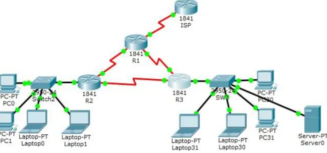
Escenario 1
Part 1: El administrador
Part 2:
Part 3: Interfaces Part 4:
Part 5: Dirección IP Part 6: M áscara de subred
Part 7: G ateway
predeterminad o
Part 8: ISP Part 9: S0/0/0 Part 10: 200.123.211.1 Part 11: 255.255.255.0 Part 12: N/D Part 13:
Part 14: R1
Part 15: Se0/0/0 Part 16: 200.123.211.2 Part 17: 255.255.255.0 Part 18: N/D Part 19: Se0/1/0 Part 20: 10.0.0.1 Part 21: 255.255.255.252 Part 22: N/D Part 23: Se0/1/1 Part 24: 10.0.0.5 Part 25: 255.255.255.252 Part 26: N/D Part 27:
Part 28:
Part 29: R2
Part 30: Fa0/0,100 Part 31: 192.168.20.1 Part 32: 255.255.255.0 Part 33: N/D Part 34: Fa0/0,200 Part 35: 192.168.21.1 Part 36: 255.255.255.0 Part 37: N/D Part 38: Se0/0/0 Part 39: 10.0.0.2 Part 40: 255.255.255.252 Part 41: N/D Part 42: Se0/0/1 Part 43: 10.0.0.9 Part 44: 255.255.255.252 Part 45: N/D Part 46:
Part 47:
Part 48: R3
Part 49:
Part 50: Fa0/0 Part 51: 192.168.30.1 Part 52: 255.255.255.0 Part 53: N/D Part 54: 2001:db8:130::9C0:80F:301 Part 55: /64 Part 56: N/D Part 57: Se0/0/0 Part 58: 10.0.0.6 Part 59: 255.255.255.252 Part 60: N/D Part 61: Se0/0/1 Part 62: 10.0.0.10 Part 63: 255.255.255.252 Part 64: N/D Part 65: SW2 Part 66: VLAN 100 Part 67: N/D Part 68: N/D Part 69: N/D Part 70: Part 71: VLAN 200 Part 72: N/D Part 73: N/D Part 74: N/D Part 75: SW3 Part 76: VLAN1 Part 77: N/D Part 78: N/D Part 79: N/D
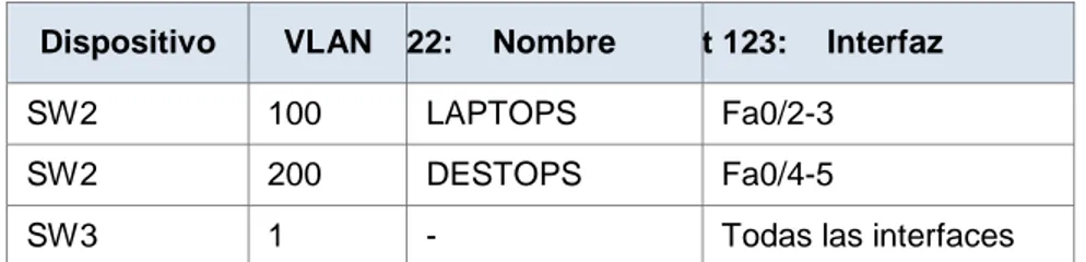
Tabla de asignación de VLAN y de puertos
Part 120: Dispositivo Part 121: VLAN Part 122: Nombre Part 123: Interfaz
Part 124: SW2 Part 125: Part 126: 100 LAPTOPS Part 127: Fa0/2-3 Part 128: SW2 Part 129: Part 130: 200 DESTOPS Part 131: Fa0/4-5
Part 132: SW3 Part 133: Part 134: 1 - Part 135: Todas las interfaces
Tabla de enlaces troncales
Part 136: Dispositivo local Part 137: Interfaz local Part 138: Dispositivo remoto
Part 139: SW2 Part 140: Fa0/2-3 Part 141: 100
Situación
En esta actividad, demostrará y reforzará su capacidad para implementar
NAT, servidor de DHCP, RIPV2 y el routing entre VLAN, incluida la
configuración de direcciones IP, las VLAN, los enlaces troncales y las
subinterfaces. Todas las pruebas de alcance deben realizarse a través de ping
únicamente.
Descripción de las actividades
•
SW1
VLAN y las asignaciones de puertos de VLAN deben cumplir con la
tabla 1.
SW2(config)#vlan 100
SW2(config-vlan)#name LAPTOPS
SW2(config-vlan)#exit
SW2(config)#vlan 200
SW2(config-vlan)#name DESTOPS
SW2(config-vlan)#exit
SW2(config)#interface range fa0/2-3
SW2(config-if-range)#switchport mode Access
SW2(config-if-range)#exit
SW2(config)#interface range fa0/4-5
SW2(config-if-range)#switchport mode Access
SW2(config-if-range)#switch access vlan 200
SW2(config-if-range)#exit
SW2(config)#interface fa0/1
SW2(config-if)#switchport mode trunk
SW2(config-if)#exit
•
Los puertos de red que no se utilizan se deben deshabilitar.
SW2
SW2(config)#interface range fa0/6-24
SW2(config-if-range)#shutdown
%LINK-5-CHANGED: Interface FastEthernet0/6, changed state to administratively down
%LINK-5-CHANGED: Interface FastEthernet0/7, changed state to administratively down
%LINK-5-CHANGED: Interface FastEthernet0/8, changed state to administratively down
%LINK-5-CHANGED: Interface FastEthernet0/9, changed state to administratively down
%LINK-5-CHANGED: Interface FastEthernet0/10, changed state to administratively down
%LINK-5-CHANGED: Interface FastEthernet0/11, changed state to administratively down
%LINK-5-CHANGED: Interface FastEthernet0/12, changed state to administratively down
%LINK-5-CHANGED: Interface FastEthernet0/13, changed state to administratively down
%LINK-5-CHANGED: Interface FastEthernet0/14, changed state to administratively down
%LINK-5-CHANGED: Interface FastEthernet0/16, changed state to administratively down
%LINK-5-CHANGED: Interface FastEthernet0/17, changed state to administratively down
%LINK-5-CHANGED: Interface FastEthernet0/18, changed state to administratively down
%LINK-5-CHANGED: Interface FastEthernet0/19, changed state to administratively down
%LINK-5-CHANGED: Interface FastEthernet0/20, changed state to administratively down
%LINK-5-CHANGED: Interface FastEthernet0/21, changed state to administratively down
%LINK-5-CHANGED: Interface FastEthernet0/22, changed state to administratively down
%LINK-5-CHANGED: Interface FastEthernet0/23, changed state to administratively down
%LINK-5-CHANGED: Interface FastEthernet0/24, changed state to administratively down
SW2(config-if-range)#exit
SW3
SW3(config)#interface range fa0/6-23
SW3(config-if-range)#shutdown
%LINK-5-CHANGED: Interface FastEthernet0/6, changed state to administratively down
%LINK-5-CHANGED: Interface FastEthernet0/7, changed state to administratively down
%LINK-5-CHANGED: Interface FastEthernet0/8, changed state to administratively down
%LINK-5-CHANGED: Interface FastEthernet0/9, changed state to administratively down
%LINK-5-CHANGED: Interface FastEthernet0/11, changed state to administratively down
%LINK-5-CHANGED: Interface FastEthernet0/12, changed state to administratively down
%LINK-5-CHANGED: Interface FastEthernet0/13, changed state to administratively down
%LINK-5-CHANGED: Interface FastEthernet0/14, changed state to administratively down
%LINK-5-CHANGED: Interface FastEthernet0/15, changed state to administratively down
%LINK-5-CHANGED: Interface FastEthernet0/16, changed state to administratively down
%LINK-5-CHANGED: Interface FastEthernet0/17, changed state to administratively down
%LINK-5-CHANGED: Interface FastEthernet0/18, changed state to administratively down
%LINK-5-CHANGED: Interface FastEthernet0/19, changed state to administratively down
%LINK-5-CHANGED: Interface FastEthernet0/20, changed state to administratively down
%LINK-5-CHANGED: Interface FastEthernet0/21, changed state to administratively down
%LINK-5-CHANGED: Interface FastEthernet0/22, changed state to administratively down
%LINK-5-CHANGED: Interface FastEthernet0/23, changed state to administratively down
SW3(config-if-range)#
•
La información de dirección IP R1, R2 y R3 debe cumplir con la tabla 1.
R1
R1(config)#interface s0/0/0
R1(config-if)#ip address 200.123.211.2 255.255.255.0
R1(config-if)#exit
R1(config)#interface s0/1/0
R1(config-if)#ip address 10.0.0.1 255.255.255.252
R1(config-if)#no shutdown
R1(config-if)#exit
R1(config)#interface s0/1/1
R1(config-if)#ip address 10.0.0.5 255.255.255.252
R1(config-if)#no shutdown
R1(config-if)#exit
R1(config)#
R2
R2>enableR2#config t
Enter configuration commands, one per line. End with CNTL/Z.
R2(config)#interface f0/0.100
R2(config-subif)#
%LINK-5-CHANGED: Interface FastEthernet0/0.100, changed state to up
%LINEPROTO-5-UPDOWN: Line protocol on Interface FastEthernet0/0.100, changed state to up
R2(config-subif)#encapsulation dot1Q 100
R2(config-subif)#ip address 192.168.20.1 255.255.255.0
R2(config-subif)#exit
R2(config)#interface f0/0.200
R2(config-subif)#
%LINEPROTO-5-UPDOWN: Line protocol on Interface FastEthernet0/0.200, changed state to up
R2(config-subif)#encapsulation dot1Q 200
R2(config-subif)#ip address 192.168.21.1 255.255.255.0
R2(config-subif)#exit
R2(config)#interface f0/0
R2(config-if)#no shutdown
R2(config-if)#exit
R2(config)#interface f0/0%DHCPD-4-PING_CONFLICT: DHCP address conflict: server pinged
R2(config)#interface s0/0/0
R2(config-if)#ip address 10.0.0.2 255.255.255.252
R2(config-if)#no shutdown
R2(config-if)#exit
R2(config)#interface s0/0/1
R2(config-if)#ip address 10.0.0.9 255.255.255.252
R2(config-if)#no shutdown
R2(config-if)#exit
R2(config)#
R3
R3(config)#ipv6 unicast-routing
R3(config)#interface f0/0
R3(config-if)#ip address 192.168.30.1 255.255.255.0
R3(config-if)#ipv6 address 2001:db8:130::9C0:80F:301/64
R3(config-if)#ipv6 dhcp server vlan_1
R3(config-if)#ipv6 nd other-config-flag
R3(config-if)#exit
R3(config)#interface s0/0/0
R3(config-if)#ip address 10.0.0.6 255.255.255.252
R3(config-if)#no shutdown
R3(config-if)#exit
R3(config)#interface s0/0/1
R3(config-if)#ip address 10.0.0.10 255.255.255.252
R3(config-if)#no shutdown
R3(config-if)#exit
R3(config)#
•
R1
debe realizar una NAT con sobrecarga sobre una dirección IPv4
pública. Asegúrese de que todos los terminales pueden comunicarse
con Internet pública (haga ping a la dirección ISP) y la lista de acceso
estándar se llama INSIDE-DEVS.
R1(config)#ip nat pool INSIDE-DEVS 200.123.211.2 200.123.211.128 netmask 255.255.255.0
R1(config)#access-list 1 permit 192.168.0.0 0.0.255.255
R1(config)#access-list 1 permit 10.0.0.0 0.0.255.255
R1(config)#ip nat inside source list 1 interface s0/0/0 overload
R1(config)#interface s0/1/0
R1(config-if)#ip nat inside
R1(config-if)#exit
R1(config)#interface s0/1/1
R1(config-if)#ip nat inside
R1(config-if)#exit
R1(config)#interface s0/0/0
R1(config-if)#ip nat outside
R1(config)#
•
R1
debe tener una ruta estática predeterminada al ISP que se
configuró y que incluye esa ruta en el dominio RIPv2.
R1(config)#router rip
R1(config-router)#version 2
R1(config-router)#ip route 0.0.0.0 0.0.0.0 s0/0/0
R1(config)#router rip
R1(config-router)#network 10.0.0.4
R1(config-router)#network 10.0.0.0
R1(config-router)#default-information originate
R1(config-router)#exit
R1(config)#
•
R2
es un servidor de DHCP para los dispositivos conectados al puerto
FastEthernet0/0.
R3(config)#ip dhcp pool vlan_1
R3(dhcp-config)#network 192.168.30.1 255.255.255.0
R3(dhcp-config)#default-router 192.168.30.1
R3(dhcp-config)#ipv6 dhcp pool vlan_1
R3(config-dhcpv6)#dns-server 2001:db8:130::
R3(config-dhcpv6)#exit
R3(config)#
•
R2
debe, además de enrutamiento a otras partes de la red, ruta entre las
VLAN 100 y 200.
R2(config)#ip dhcp pool vlan_100
R2(dhcp-config)#network 192.168.20.1 255.255.255.0
R2(dhcp-config)#exit
R2(config)#ip dhcp pool vlan_200
R2(dhcp-config)#network 192.168.21.1 255.255.255.0
R2(dhcp-config)#default-router 192.168.21.1
R2(dhcp-config)#exit
R2(config)#
•
El Servidor0 es sólo un servidor IPv6 y solo debe ser accesibles para los
dispositivos en R3 (ping).
•
La interfaz FastEthernet 0/0 del R3 también deben tener direcciones
IPv4 e IPv6 configuradas (dual- stack).
R3(config)#ipv6 unicast-routing
R3(config)#interface f0/0
R3(config-if)#ip address 192.168.30.1 255.255.255.0
R3(config-if)#ipv6 address 2001:db8:130::9C0:80F:301/64
R3(config-if)#ipv6 dhcp server vlan_1
R3(config-if)#ipv6 nd other-config-flag
R3(config-if)#no shutdown
•
R1, R2 y R3 intercambian información de routing mediante RIP versión 2.
R1(config)#router rip
R1(config-router)#version 2
R1(config-router)#ip route 0.0.0.0 0.0.0.0 s0/0/0
R1(config-router)#network 10.0.0.0
R1(config-router)#default-information originate
R1(config-router)#exit
R1(config)#
R2(config)#router rip
R2(config-router)#version 2
R2(config-router)#network 192.168.30.0
R2(config-router)#network 192.168.20.0
R2(config-router)#network 192.168.21.0
R2(config-router)#network 10.0.0.0
R2(config-router)#network 10.0.0.8
R2(config-router)#exit
R2(config)#
R3(config)#router rip
R3(config-router)#version 2
R3(config-router)#network 192.168.0.0
R3(config-router)#network 10.0.0.8
R3(config-router)#network 10.0.0.4
R3(config-router)#exit
R3(config)#
•
R1, R2 y R3 deben saber sobre las rutas de cada uno y la ruta
predeterminada desde R1.
R3(config)#ipv6 unicast-routing
R3(config)#interface f0/0
R3(config-if)#ip address 192.168.30.1 255.255.255.0
R3(config-if)#ipv6 dhcp server vlan_1
R3(config-if)#ipv6 nd other-config-flag
R3(config-if)#no shutdown
R3(config-if)#exit
R3(config)#interface s0/0/0
R3(config-if)#ip address 10.0.0.6 255.255.255.252
R3(config-if)#no shutdown
R3(config-if)#exit
R3(config)#interface s0/0/1
R3(config-if)#ip address 10.0.0.10 255.255.255.252
R3(config-if)#no shutdown
R3(config-if)#exit
R3(config)#
Escenario 2
Escenario: Una empresa de Tecnología posee tres sucursales distribuidas en las
ciudades de Miami, Bogotá y Buenos Aires, en donde el estudiante será el
administrador de la red, el cual deberá configurar e interconectar entre sí cada uno
de los dispositivos que forman parte del escenario, acorde con los lineamientos
establecidos para el direccionamiento IP, protocolos de enrutamiento y demás
aspectos que forman parte de la topología de red.
1. Configurar el direccionamiento IP acorde con la topología de red para cada
uno de los dispositivos que forman parte del escenario
Maimi
R2(config)#interface s0/0/1
%LINK-5-CHANGED: Interface Serial0/0/1, changed state to down R2(config-if)#exit
R2(config)#interface s0/0/0
R2(config-if)#ip address 172.31.23.1 255.255.255.252 R2(config-if)#no shutdown
%LINK-5-CHANGED: Interface Serial0/0/0, changed state to down R2(config)#interface gi0/0
R2(config-if)#ip address 209.165.200.225 255.255.255.248 R2(config-if)#no shutdown
R2(config-if)#
%LINK-5-CHANGED: Interface GigabitEthernet0/0, changed state to up
%LINEPROTO-5-UPDOWN: Line protocol on Interface GigabitEthernet0/0, changed state to up
R2(config-if)#exit
R2(config)#interface lo0
R2(config-if)#
%LINK-5-CHANGED: Interface Loopback0, changed state to up
%LINEPROTO-5-UPDOWN: Line protocol on Interface Loopback0, changed state to up
R2(config-if)#ip address 10.10.10.11 255.255.255.255 R2(config-if)#exit
R2(config)#
Bogotá
Router>enable Router#config tEnter configuration commands, one per line. End with CNTL/Z. Router(config)#hostname R1
R1(config)#interface serial0/0/0
R1(config-if)#ip address 172.31.21.2 255.255.255.252 R1(config-if)#no shutdown
R1(config-if)#
%LINK-5-CHANGED: Interface Serial0/0/0, changed state to up
%LINEPROTO-5-UPDOWN: Line protocol on Interface Serial0/0/0, changed state to up
R1(config)#interface gi0/0
R1(config-if)#ip address 192.168.30.1 255.255.255.0 R1(config-if)#no shutdown
R1(config-if)#
%LINK-5-CHANGED: Interface GigabitEthernet0/0, changed state to up
%LINEPROTO-5-UPDOWN: Line protocol on Interface GigabitEthernet0/0, changed state to up
R1(config-if)#exit R1(config)#
Buenos Aires
R3(config)#interface serial0/0/1
R3(config-if)#ip address 172.31.23.2 255.255.255.252 R3(config-if)#no shutdown
R3(config-if)#
%LINK-5-CHANGED: Interface Serial0/0/1, changed state to up
R3(config-if)#
%LINEPROTO-5-UPDOWN: Line protocol on Interface Serial0/0/1, changed state to up
R3(config-if)#exit
R3(config)#interface lo4
R3(config-if)#
%LINK-5-CHANGED: Interface Loopback4, changed state to up
%LINEPROTO-5-UPDOWN: Line protocol on Interface Loopback4, changed state to up
R3(config-if)#ip address 192.168.4.1 255.255.255.0 R3(config-if)#exit
R3(config)#interface lo5
R3(config-if)#
%LINEPROTO-5-UPDOWN: Line protocol on Interface Loopback5, changed state to up
R3(config-if)#ip address 192.168.5.1 255.255.255.0 R3(config-if)#exit
R3(config)#interface lo6
R3(config-if)#
%LINK-5-CHANGED: Interface Loopback6, changed state to up
%LINEPROTO-5-UPDOWN: Line protocol on Interface Loopback6, changed state to up
R3(config-if)#ip address 192.168.6.1 255.255.255.0 R3(config-if)#exit
R3(config)#
PC-A
2. Configurar el protocolo de enrutamiento OSPFv2 bajo los siguientes criterios:
OSPFv2 area 0
Configuration Item or Task Specification
Router ID R1 1.1.1.1
Router ID R2
5.5.5.5 Router ID R3
8.8.8.8 Configurar todas las interfaces LAN como pasivas
Establecer el ancho de banda para enlaces seriales en 256 Kb/s Ajustar el costo en la métrica de S0/0 a 9500
Verificar información de OSPF
•
Visualizar tablas de enrutamiento y routers conectados por OSPFv2
•
Visualizar lista resumida de interfaces por OSPF en donde se ilustre el
costo de cada interface
•
Visualizar el OSPF Process ID, Router ID, Address summarizations,
Routing Networks, and passive interfaces configuradas en cada router.
R1(config)#router ospf 1
R1(config-router)#router-id 1.1.1.1
R1(config-router)#passive-interface gi0/0 R1(config-router)#exit
R1(config)#
R2(config)#router ospf 1
R2(config-router)#router-id 5.5.5.5
R2(config-router)#exit R2(config)#
R3(config)#router ospf 1
R3(config-router)#router-id 8.8.8.8 R3(config-router)#exit
R3(config)#
R1#show ip route
R1#show ip route
Codes: L - local, C - connected, S - static, R - RIP, M - mobile, B - BGP
D - EIGRP, EX - EIGRP external, O - OSPF, IA - OSPF inter area N1 - OSPF NSSA external type 1, N2 - OSPF NSSA external type 2 E1 - OSPF external type 1, E2 - OSPF external type 2, E - EGP i - IS-IS, L1 - IS-IS level-1, L2 - IS-IS level-2, ia - IS-IS inter area
* - candidate default, U - per-user static route, o - ODR P - periodic downloaded static route
Gateway of last resort is not set
172.31.0.0/16 is variably subnetted, 2 subnets, 2 masks C 172.31.21.0/30 is directly connected, Serial0/0/0 L 172.31.21.2/32 is directly connected, Serial0/0/0
192.168.30.0/24 is variably subnetted, 2 subnets, 2 masks C 192.168.30.0/24 is directly connected, GigabitEthernet0/0 L 192.168.30.1/32 is directly connected, GigabitEthernet0/0
R1#
R2#show ip route
R2#show ip route
Codes: L - local, C - connected, S - static, R - RIP, M - mobile, B - BGP
D - EIGRP, EX - EIGRP external, O - OSPF, IA - OSPF inter area N1 - OSPF NSSA external type 1, N2 - OSPF NSSA external type 2 E1 - OSPF external type 1, E2 - OSPF external type 2, E - EGP i - IS-IS, L1 - IS-IS level-1, L2 - IS-IS level-2, ia - IS-IS inter area
* - candidate default, U - per-user static route, o - ODR P - periodic downloaded static route
10.0.0.0/32 is subnetted, 1 subnets
C 10.10.10.11/32 is directly connected, Loopback0
172.31.0.0/16 is variably subnetted, 4 subnets, 2 masks C 172.31.21.0/30 is directly connected, Serial0/0/1 L 172.31.21.1/32 is directly connected, Serial0/0/1 C 172.31.23.0/30 is directly connected, Serial0/0/0 L 172.31.23.1/32 is directly connected, Serial0/0/0
209.165.200.0/24 is variably subnetted, 2 subnets, 2 masks C 209.165.200.224/29 is directly connected, GigabitEthernet0/0 L 209.165.200.225/32 is directly connected, GigabitEthernet0/0
R2#
R3#show ip route
R3#show ip route
Codes: L - local, C - connected, S - static, R - RIP, M - mobile, B - BGP
D - EIGRP, EX - EIGRP external, O - OSPF, IA - OSPF inter area N1 - OSPF NSSA external type 1, N2 - OSPF NSSA external type 2 E1 - OSPF external type 1, E2 - OSPF external type 2, E - EGP i - IS-IS, L1 - IS-IS level-1, L2 - IS-IS level-2, ia - IS-IS inter area
* - candidate default, U - per-user static route, o - ODR P - periodic downloaded static route
Gateway of last resort is not set
172.31.0.0/16 is variably subnetted, 2 subnets, 2 masks C 172.31.23.0/30 is directly connected, Serial0/0/1 L 172.31.23.2/32 is directly connected, Serial0/0/1 192.168.4.0/24 is variably subnetted, 2 subnets, 2 masks C 192.168.4.0/24 is directly connected, Loopback4
L 192.168.4.1/32 is directly connected, Loopback4
192.168.5.0/24 is variably subnetted, 2 subnets, 2 masks C 192.168.5.0/24 is directly connected, Loopback5
L 192.168.5.1/32 is directly connected, Loopback5
192.168.6.0/24 is variably subnetted, 2 subnets, 2 masks C 192.168.6.0/24 is directly connected, Loopback6
L 192.168.6.1/32 is directly connected, Loopback6
3. Configurar VLANs, Puertos troncales, puertos de acceso, encapsulamiento,
Inter-VLAN Routing y Seguridad en los Switches acorde a la topología de
red establecida.
VLANs
S1(config)#vlan 30 S1(config-vlan)#name Administracion S1(config-vlan)#exit S1(config)#vlan 40 S1(config-vlan)#name Mercadeo S1(config-vlan)#exit S1(config)#vlan 200 S1(config-vlan)#name Mantenimiento S1(config-vlan)#exit S1(config)# S3(config-if)#exit S3(config)#vlan 30 S3(config-vlan)#name Administracion S3(config-vlan)#exit S3(config)#vlan 40 S3(config-vlan)#name Mercadeo S3(config-vlan)#exit S3(config)#vlan 200 S3(config-vlan)#name Mantenimiento S3(config-vlan)#exit S3(config)#Puertos troncales
S1(config)#interface gi0/1S1(config-if)#switchport mode trunk S1(config-if)#
S3(config)#interface gi0/1
S3(config-if)#switchport mode trunk
S3(config-if)#
%LINEPROTO-5-UPDOWN: Line protocol on Interface GigabitEthernet0/1, changed state to up
S3(config-if)#
Puertos de acceso
S1(config)#interface fa0/1
S1(config-if)#switchport mode access S1(config-if)#switchport access vlan 30 S1(config-if)#
S3(config)#interface fa0/1
S3(config-if)#switchport mode access S3(config-if)#switchport access vlan 40 S3(config-if)#
4. En el Switch 3 deshabilitar DNS lookup
S3(config)#no ip domain-lookup S3(config)#
5. Asignar direcciones IP a los Switches acorde a los lineamientos.
S1(config)#interface vlan 99
S1(config-if)#ip address 192.168.99.2 255.255.255.0 S1(config-if)#no shutdown
S1(config-if)
S3(config)#interface vlan 99
S3(config-if)#ip address 192.168.99.3 255.255.255.0 S3(config-if)#no shutdown
S3(config-if)#
6. Desactivar todas las interfaces que no sean utilizadas en el esquema de
red.
S1(config-if-range)#shutdown
%LINK-5-CHANGED: Interface FastEthernet0/2, changed state to administratively down
%LINK-5-CHANGED: Interface FastEthernet0/3, changed state to administratively down
%LINK-5-CHANGED: Interface FastEthernet0/4, changed state to administratively down
%LINK-5-CHANGED: Interface FastEthernet0/5, changed state to administratively down
%LINK-5-CHANGED: Interface FastEthernet0/6, changed state to administratively down
%LINK-5-CHANGED: Interface FastEthernet0/7, changed state to administratively down
%LINK-5-CHANGED: Interface FastEthernet0/8, changed state to administratively down
%LINK-5-CHANGED: Interface FastEthernet0/9, changed state to administratively down
%LINK-5-CHANGED: Interface FastEthernet0/10, changed state to administratively down
%LINK-5-CHANGED: Interface FastEthernet0/11, changed state to administratively down
%LINK-5-CHANGED: Interface FastEthernet0/12, changed state to administratively down
%LINK-5-CHANGED: Interface FastEthernet0/13, changed state to administratively down
%LINK-5-CHANGED: Interface FastEthernet0/14, changed state to administratively down
%LINK-5-CHANGED: Interface FastEthernet0/15, changed state to administratively down
%LINK-5-CHANGED: Interface FastEthernet0/16, changed state to administratively down
%LINK-5-CHANGED: Interface FastEthernet0/18, changed state to administratively down
%LINK-5-CHANGED: Interface FastEthernet0/19, changed state to administratively down
%LINK-5-CHANGED: Interface FastEthernet0/20, changed state to administratively down
%LINK-5-CHANGED: Interface FastEthernet0/21, changed state to administratively down
%LINK-5-CHANGED: Interface FastEthernet0/22, changed state to administratively down
%LINK-5-CHANGED: Interface FastEthernet0/23, changed state to administratively down
S1(config-if-range)#
%LINK-5-CHANGED: Interface FastEthernet0/24, changed state to administratively down
%LINEPROTO-5-UPDOWN: Line protocol on Interface FastEthernet0/24, changed state to down
S1(config-if-range)#
S3(config)#interface range fa0/2-24 S3(config-if-range)#shutdown
%LINK-5-CHANGED: Interface FastEthernet0/2, changed state to administratively down
%LINK-5-CHANGED: Interface FastEthernet0/3, changed state to administratively down
%LINK-5-CHANGED: Interface FastEthernet0/4, changed state to administratively down
%LINK-5-CHANGED: Interface FastEthernet0/5, changed state to administratively down
%LINK-5-CHANGED: Interface FastEthernet0/7, changed state to administratively down
%LINK-5-CHANGED: Interface FastEthernet0/8, changed state to administratively down
%LINK-5-CHANGED: Interface FastEthernet0/9, changed state to administratively down
%LINK-5-CHANGED: Interface FastEthernet0/10, changed state to administratively down
%LINK-5-CHANGED: Interface FastEthernet0/11, changed state to administratively down
%LINK-5-CHANGED: Interface FastEthernet0/12, changed state to administratively down
%LINK-5-CHANGED: Interface FastEthernet0/13, changed state to administratively down
%LINK-5-CHANGED: Interface FastEthernet0/14, changed state to administratively down
%LINK-5-CHANGED: Interface FastEthernet0/15, changed state to administratively down
%LINK-5-CHANGED: Interface FastEthernet0/16, changed state to administratively down
%LINK-5-CHANGED: Interface FastEthernet0/17, changed state to administratively down
%LINK-5-CHANGED: Interface FastEthernet0/18, changed state to administratively down
%LINK-5-CHANGED: Interface FastEthernet0/19, changed state to administratively down
%LINK-5-CHANGED: Interface FastEthernet0/20, changed state to administratively down
%LINK-5-CHANGED: Interface FastEthernet0/21, changed state to administratively down
%LINK-5-CHANGED: Interface FastEthernet0/23, changed state to administratively down
S3(config-if-range)#
7. Implement DHCP and NAT for IPv4
R1(config)#ip dhcp excluded-address 192.168.30.2 192.168.30.32 R1(config)#ip dhcp excluded-address 192.168.40.2 192.168.40.32 R1(config)#
8. Configurar R1 como servidor DHCP para las VLANs 30 y 40.
R1(config)#service dhcp R1(config)#
9. Reservar las primeras 30 direcciones IP de las VLAN 30 y 40 para
configuraciones estáticas.
R1(config)#ip dhcp excluded-address 192.168.30.2 192.168.30.32 R1(config)#ip dhcp excluded-address 192.168.40.2 192.168.40.32 R1(config)#
Configurar DHCP pool para
VLAN 30
Name: ADMINISTRACION
DNS-Server: 10.10.10.11
Domain-Name: ccna-unad.com
Establecer default gateway.
Configurar DHCP pool para
VLAN 40
Name: MERCADEO
DNS-Server: 10.10.10.11
Domain-Name: ccna-unad.com
Establecer default gateway.
R1(config)#ip dhcp pool ADMINISTRACION R1(dhcp-config)#dns-server 10.10.10.11 R1(dhcp-config)#default-router 172.31.21.1 R1(dhcp-config)#domain-name ccna-unad.com ^
% Invalid input detected at '^' marker.
R1(dhcp-config)#network 172.31.21.1 255.255.255.0 R1(dhcp-config)#exit
R1(config)#ip dhcp pool MERCADEO
R1(dhcp-config)#dns-server 10.10.10.11 R1(dhcp-config)#default-router 172.31.21.1
R1(dhcp-config)#network 172.31.21.1 255.255.255.0 R1(dhcp-config)#domain-name ccna-unad.com
^
% Invalid input detected at '^' marker. R1(dhcp-config)#EXIT
R1(config)#
10. Configurar NAT en R2 para permitir que los host puedan salir a internet
R2(config)#ip access-list extended ADMINISTRACION R2(config-ext-nacl)#remark permit local lan to use nat R2(config-ext-nacl)#permit ip 192.168.30.0 0.0.0.255 any R2(config-ext-nacl)#permit ip 192.168.40.0 0.0.0.255 any R2(config-ext-nacl)#exit
R2(config)#ip nat pool R1-pool 209.165.200.225 209.165.200.228 netmask 255.255.255.248
R2(config)#ip nat inside source list ADMINISTRACION pool Bogota-pool
R2(config)#interface lo0 R2(config-if)#ip nat inside
R2(config-if)#interface serial0/0/1 R2(config-if)#ip nat outside
R2(config-if)#
11. Configurar al menos dos listas de acceso de tipo estándar a su criterio en
para restringir o permitir tráfico desde R1 o R3 hacia R2.
R2(config)#ip access-list standard MERCADEO R2(config-std-nacl)#permit host 172.31.21.1 R2(config-std-nacl)#permit host 172.31.21.2
R2(config)#access-list 1 permit 192.168.99.0 0.0.0.255
12. Configurar al menos dos listas de acceso de tipo extendido o nombradas a
su criterio en para restringir o permitir tráfico desde R1 o R3 hacia R2.
R2(config)#