Propuesta de entrepiso para viviendas de uno y dos pisos en sistema constructivo liviano: Evaluación a carga vertical estática y modelación en elementos finitos
9
0
0
Texto completo
(2) Ingeniería y Competitividad, Volumen 16, No. 1, p. 239 - 247 (2014). 1. Introduction In order to reduce costs, housing in conventional construction systems is usually built without consulting a specialized engineer and without the technical specifications required. This is responsible for failures in their structural behaviors during seismic events. According to ASOCRETO (1995), this can be evidenced in the damage of structural elements, such as slab system, in which cracks by punching shear and longitudinal cracks are generated due to excessive shear and flexion stress exerted by the seism. One of the challenges faced by the construction field is the development of building methods able to produce more efficient structures in terms of building time, cost and behavior in the demands they will be exposed to. According to Murcia (1997), non-traditional industrialized construction systems have gradually become a favorable option for the construction of social interest housing projects, considering that applying a non-traditional system implies savings of 40% as compared to the use of a traditional system. A particular case is the system proposed by the Perfilamos del Cauca S.A. company, which consists of building houses with light bearing walls composed of boards linked to cold-formed joists whose performance depends a great deal on the slab system implemented, so that it can adequately transmit vertical and horizontal loads to the walls with a structure that adds little weight and cost to the house. The results of the studies previously carried out by Wei-Wen (2000) have indicated that shear resistance of a composite slab is usually affected by panel configuration, panel and support beams separation, thickness of materials, acoustic perforations, connection types and arrangements, and filling concrete, if any. Taking that into account, this study proposes the use of a lightweight ferrocement slab linked to lightweight cold-formed joists through shear connectors. This slab proposal needs to be evaluated and designed in order to guarantee the composite section working of its elements and compliance to the stipulations in the Reglamento Colombiano de Construcción Sismo-Resistente. 240. NSR-10, in terms of the resistance and rigidity that it should give to the system. This article describes the static vertical load experimental evaluation of the slab proposal for the lightweight wall system, as well as the validation of a computational model which can be used as a design tool for this type of slab systems. It is important to note that this work is part of a macro research project developed by Colciencias, Universidad del Valle and Perfilamos del Cauca S.A.. 2. Slab design as a composite section. Testing and modeling Composite section behavior is achieved when connecting steel joist to the reinforced concrete slab that it supports, so that the two parts act as a unit. This behavior, according to Segui (2000), is only possible if the horizontal sliding between the two components is prevented with connection devices, known as shear connectors. Depending on the number of connectors, it will be possible to obtain a totally or partially composite section, the latter being one without enough connectors to develop the total resistance of the composite beam, according to McCormac (2002). In order to determine the amount of connectors needed to secure a totally composite section, under the ultimate resistance design philosophy (LRFD), the formulas given by Eq. (1) and Eq. (2) can be used.. V N1 = Qh n. (1). Qn = 0.5Asc fc Ec # Asc Fu. (2). Where N1 is the number of shear connectors required, Vh is horizontal shear force in Kips, Qn is nominal shear resistance of a connector in Kips, Asc is concrete transversal area in in2; fc is concrete resistance to compression after 28 days in ksi; Ec is concrete elasticity module in ksi; and Fu is the connector minimal tensile resistance in ksi. In addition, slab flexion resistance as a composite section can be determined by means of Eq. (3) when the neutral plastic axle is located in the slab.. a Mn = Asfy � d+t- 2j. (3).
(3) Ingeniería y Competitividad, Volumen 16, No. 1, p. 239 - 247 (2014). Where Mn is nominal resistance to flexion; fy is joist steel yield stress; d is distance from the extreme compression fiber to the centroid of the longitudinal traction stress; t is ferrocement slab thickness; and a is the location of the neutral plastic axle. Floor diaphragms are modeled with beams that carry the forces on the plan to rigid points of the structure. The plate or slab acts as a covering of the joists system and in the edge elements it acts as the flange of the joist. The rigidity and ultimate resistance of a floor diaphragm must be established by the designer. Predictions of those quantities can be made using one of the approaches used by AISI (2005), which are: approximate design, finite element analysis and/or empirical design.. head galvanized steel screws, plus 1/4” washers, arranged all along the joists, every 15 cm (type I specimens: partially composite section) and every 8 cm (type II specimens: totally composite section). The ferrocement used in the plate was composed of a mortar matrix with sand/cement ratio = 2.5, as recommended by Wasinshtok, H. (1998), and reinforced with four layers of high corrosion resistance hexagonal caliber 24 galvanized wire mesh of a 1/2” of hole.. 3. Methodology 3.1 Laboratory testing For the implementation of the slab system under study it must be experimentally guaranteed that the materials and elements to be used have adequate behavior to flexion. For this, it is necessary to carry out full-scale tests, so that the connectors of the composite slab are under the combination of the action by the flexion and shear forces. Likewise, in order to generate a constant moment in the central zone of the specimen’s span and to have enough shear length for the effects of the normal shear forces in the interface of the elements to be meaningful, it is convenient that in these tests the load be applied in the central thirds of the specimen’s span, according to Jeon et al. (2007) and Bhavani & Yi (2005). 3.1.1 Description of specimens Three full-scale 2.05 m wide by 3.20m long specimens were built, formed with five P4 x 2 x 1.2 joists with a 50 cm separation between axes, joined with web stiffeners (8 cm - long P4 x 2 x 1.2 joists) to two C4 x 2 x 1.2 tracks. The resulting metal framework was linked to a 3cm thick ferrocement slab through shear connectors consisting of 11/2” #10 self-tapping hexagonal. Figure 1. Constructive process and test set-up. 3.1.2 Setup description Specimens were built over two supports obtaining a 3.00m span. Through a beam framework a load was applied on the thirds of the span. To apply the load, a steel reaction frame was used, which was connected to a hydraulic cylinder with a pancake type tractioncompression 10000 lb capacity model LCF450 load cell on its lower end in order to record and control the magnitude of the load applied during the test. In the lower part of the specimen a type LD610-50 Lvdt was placed under each joist in order to record the displacement produced by the load. (Figure 2). 241.
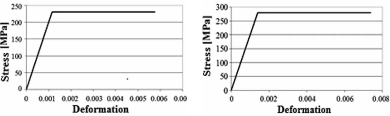
(4) Ingeniería y Competitividad, Volumen 16, No. 1, p. 239 - 247 (2014). Figure 2. Type I and Type II Specimens Flection Test Results. 3.1.3 Characterization of materials Ferrocement The values for the ultimate compressive stress and the ferrocement elasticity module were obtained experimentally, according the research conducted by Perfilamos del Cauca et al. (2010). In addition, the values for density, ultimate tensile stress and the Poisson’s ratio were set according to Panamerican Sanitary and Environmental Engineering Center (2003). The values for the characterization of ferrocement are listed below: a) Elasticity module: 2000 MPa; b) Poisson’s ratio: 0.12; c) Density: 2300 kg/m3; d) ultimate tensile stress: 5.0 MPa; e) ultimate compress ive stress: 17.7 MPa. ASTM A568 G33 steel and galvanized steel The elasticity module of the ASTM A568 steel of the joists and the ultimate yield stress were 200000 MPa and 231 MPa, respectively. In addition, the. 242. elasticity module of galvanized steel for shear connectors and their ultimate yield stress were 190000 MPa and 280 MPa, respectively. These values were taken from Perfilamos del Cauca S.A. (2001) and were corroborated with the values obtained experimentally from Perfilamos del Cauca et al. (2010). 3.2 Finite elements modeling The analysis of cold-formed finite elements of structures plays an increasingly important role in the engineering practice since they are cost- and timeefficient as compared to laboratory tests, especially when a parametric study of a particular transversal section geometry is required, according to Wei-Xin et al. (2004). Based on this, and in order to obtain a practical design tool for the adequate simulation of static tests performed and the prediction of the slab behavior when one of its characteristics was.
(5) Ingeniería y Competitividad, Volumen 16, No. 1, p. 239 - 247 (2014). Figure 3. Bilinear Curves of joist steel and shear connector. a)ASTM A568 G33 Steel. b) Galvanized Steel. modified, a computational model was developed by using the finite element method (FEM) through the ANSYS Workbench 11.0 computer program. With this model the Type II specimen test was simulated (connectors @ 8cm), through a three dimensional, non-linear statistical analysis, according to the constitutive models of each of the materials used in the specimen (Hurtado et al, 2007). 3.2.1. Materials modeling Properties of ferrocement, steel of the joists and of the connectors were considered as elastic and isotropic for modeling purposes, taking into account the specifications described in 2.2. Steels were modeled as type BISO-Bilinear Isotropic Hardening curves which use Von Mises failure criteria and a hardening model for isotropic work; this is the commonly used option for the analysis of large deformations (Figure 3).. 3.2.2 Discretization The model was discretized using hexahedral elements for the joists and tetrahedral elements for the slab and screws. As a tetrahedral element, SOLID 187 was used to avoid problems with the irregularities of the mesh, for example where the screws and washers are joined to the slab; the element is quadratic and is defined by 10 nodes. For hexahedrons, a SOLID 185 element was used, which was defined by 8 nodes and which assigned an element size equal to 70mm. The middle nodes of the SOLID 187 element were eliminated to obtain more precise results--since the vertexes of an element are connected directly to the vertexes of adjacent elements--and less computational consumption. In those regions where deformation varied rapidly, a relatively finer mesh was required than in those regions where deformations were almost constant, as well as in those areas where contact options were defined (Figure 4).. Figure 4. Model mesh. 243.
(6) Ingeniería y Competitividad, Volumen 16, No. 1, p. 239 - 247 (2014) Table 1. Ultimate moments and experimental, theoretical and admissible deflections – Type I and II Specimens Specimen. Δserv. exp. [mm]. Δserv. theor. [mm]. %Difference. Mu [kg-m]. Mn teor. [kg-m]. %Difference. Type I: #1. 18.5. 18.9*. 2.2. 415.90. 320*. 30. Type I: #2. 18.3. 18.5*. 1.1. 480.30. 329*. 46. Type II: #3. 12.4. 11.9**. 3.9. 596.30. 471**. 21. * Values calculated with partially composite section theory * * Values calculated with composite section theory. Taking into account the symmetric distribution, both geometric and from applied loads, symmetry condition on one plane was used, just in the middle of the slab span. According to this, the model had 33644 nodes with 98685 elements. 3.2.3 Boundary and contact conditions According to the boundary conditions of the test, simple supports were used at the ends of each of the five joists. For this, compressiononly supports were used at the end of each of the joists and vertical displacement was restricted to one of them to keep the slab from behaving as a rigid element. To simulate the contacts between the joist-screws and screws-slab surfaces, bonded type contact (with no separation) was used, and no contact was defined between the slab-joist to make sure that the load were transmitted only by the screws. The elements used to define the contact option were TARGET 170 for the joist surface and for the zone of the screws in contact with the slab, and CONTACT 174 for the zones of the slab in contact with the screws and the zone of the screws in contact with the joists, which offered high aspect ratio, allowing for good discretization for analytical modelling and large deformations of the mesh before the failure. Differentiation between the TARGET 170 and CONTACT 174 elements was made necessary to better represent the behavior of steel and ferrocement in the contact zones. Finally, compatibility in the mesh was checked verifying no interference between the contact areas.. referring to the acceleration which take into account the weight of the specimen itself. Specifically, concentrate loads were applied on the slab on the thirds of the span with a magnitude equal to 2170 kg and gravity acceleration was defined as 9.8066 m/s2. In the tests, the structure load conditions and static response varied slowly in relation to time. To simulate these conditions, loads were applied in five time steps. Plasticity of the materials is a phenomenon which depends on trajectory and is not conservative, that is, the sequence to which the load is applied affects the final results. For that reason, the time in each step and the applied load were defined from the experimental test (Figure 5). 3.2.5 Type of analysis The static analysis used was non-linear by large deformities and plasticity. Convergence of forces, moments, displacements and rotations were controlled by the program.. 3.2.4 Applied forces Concentrated forces were applied, which refer to the forces applied by the actuator, and inertial loads. 244. Figure 5. Curve of load vs. time applied to model.
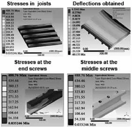
(7) Ingeniería y Competitividad, Volumen 16, No. 1, p. 239 - 247 (2014). 4. Results and discussion 4.1 Experimental results Just as presented by Larrúa (2006), failure in the specimens was produced by the separation of the slab and the joists when the maximum load resisted by the connectors was surpassed, making the joists work in simple section, that is, the beams and the slab worked as independent elements (Figure 2). This failure was ductile even after reaching the maximum load, indicating that the system will be able to stand large deflections without collapsing (Figure 2). In the specific case of the slab, cracks by tensile stress were observed in the central third, ratifying the loss of composite section, as well as localized crushing failures due to the detachment of the connectors. In all cases a difference no greater than 4% was obtained (Table 1) between the deflections obtained experimentally and those calculated theoretically, but only the Type II specimen obtained deflections under the allowed limit (12.5 mm) according to the NSR-10 developed by AIS (2009). The above indicates that the number of connectors has a great incidence on the acceptability of the system and that the design methodology outlined can be used with a high degree of reliability if it can be identified whether or not the slab is working as a totally or partially composite section. 4.2 Modeling results Once the model convergence was achieved, a maximum 6.0cm deflection was reached in the middle of the specimen span, generating large stresses in this zone, which made the specimen work in the inelastic regime (Figure 6). This deflection was similar to what was obtained experimentally, with a 10.86% difference in the final step of the load, that is, the maximum deflection obtained of the model was 10.86% less than that obtained during the test (Table 2). At the ends of the joists the values of the stresses (1310 kg/cm2) were found under the limit of the yield stress, indicating that the types of supports. Table 2. Comparison of results obtained in models and experimentally Time. Load [kg]. Deflection [mm] Test. Ansys. %Difference. 92. 453.47. 4.69. 3.55. 24.27. 184. 539.18. 6.04. 4.69. 22.36. 276. 667.65. 7.89. 6.41. 18.77. 368. 1,198.06. 16.98. 13.74. 19.09. 460. 2,170.82. 67.46. 60.13. 10.86. used simulated the test conditions adequately. The opposite occurred in the central zone, where the stresses reached values over the steel yield stress with values around 2450 kg/cm2, just like what happened in the test. The stresses obtained in the screws located at the ends of the joists were lower than those obtained in the screws located in the middle, due to the larger deformation which occurred in the central zone of the specimen. However, in both cases the stresses were under the yield stress with a greater concentration at the stem, thus inferring that the large deformations took place in this zone of the screw (Figure 6). 4.3 Validation of results The similarity between the results of the model and the experimental results was achieved by adjusting the value of the elasticity module of the ferrocement mortar, going from 20100 kg/cm2 (experimental value) to 26361kg/cm2, that is, 13% difference, and decreasing the size of the SOLID 185 element until reaching the convergence of the model. For the validation of the numeric results, a comparison was made with those obtained experimentally during the steps of load identified (Table 2).. 5. Conclusions From the full-scale experimental results of the two specimens of the proposed slab system, it was demonstrated that this type of slabs can resist the factored load to which it is going to be subject during its useful life before reaching the. 245.
(8) Ingeniería y Competitividad, Volumen 16, No. 1, p. 239 - 247 (2014). Figure 6. Model results. failure load, with a security factor equal to 1.36. In this way it is concluded that this proposed slab system can be considered as an alternative for lightweight housing construction.. difference, thus guaranteeing a validation of the method employed and a tool for slab system design when some of its geometric and/or mechanic characteristics are modified.. If in order to reduce costs of materials and installation, the slab is designed as a partially composite section, the number of connectors and adequate specimens must be implemented, so that there is no issue from the point of view of the system acceptability (admissible deflections).. 6. References. The parameters that must be taken into account to achieve an adequate adjustment of the proposed slab model are the mortar elasticity module of the ferrocement and the characteristics of the mesh used for each of the slab components (type and size of the element). The analytical model using the FEM with the help of the Ansys Ins. computational platform generated values similar to those obtained both experimentally and theoretically, with 10.86%. 246. Asociación Colombiana de Ingeniería Sísmica. (2009). Reglamento Colombiano de Construcción Sismo-Resistente, NSR-10. 3R Editores. Asociación Colombiana de Productores de Concreto Certificado – Asocreto. (1995). Reflexiones Acerca de Daños Causados por Sismos. Revista Noticreto 36. American Iron and Steel Institute - AISI. (2005). Profile of Cold-Formed Steel in Building Construction. Estados Unidos. Bhavani, S. L., & Yi, L. (2005). Experimental Study of Composite Cold-Formed Steel C-Section Floor Joists. Journal of Constructional Steel Research 62 (2006), 995–1006..
(9) Ingeniería y Competitividad, Volumen 16, No. 1, p. 239 - 247 (2014). Centro Panamericano de Ingeniería Sanitaria y del Ambiente. (2003). Especificaciones Técnicas para el Diseño de las Estructuras de Ferrocemento. Lima, Perú. Hurtado, X. F., Molina, M.,& Linero D. L. (2007). Comportamiento de Conectores de Cortante Tipo Tornillo de Resistencia Grado Dos para un Sistema de Sección Compuesta. Ingeniería e Investigación 28 (2). Jeong, Y., Kim H.,& Koo, H. (2007). Longitudinal Shear Resistance of Steel–Concrete Composite Slabs with Perfobond Shear Connectors. Journal of Constructional Steel Research 65 (2009), 81–88. Larrúa R. (2007). Perfeccionamiento de las metodologías docentes en la enseñanza de la construcción mixta en grado y postgrado en la Universidad Politécnica de Cataluña (UPC) y la Universidad de Camaguey (UC). Informe Científico, Escuela de Ingenieros de Caminos, Canales y Puertos de Barcelona Dpto. Ingeniería de la Construcción, Universidad Politécnica Cataluña, Barcelona, España. McCormac, J. C. (2002). Diseño de Estructuras de Acero Método LRFD. Editorial Alfaomega.. Murcia, F. A. (1997). Modelo de Costos para Vivienda de Interés Social a Gran Volumen. Ingeniería de la Construcción 16. Perfilamos del Cauca S.A., Universidad del Valle, Colciencias. (2010). Informe Técnico: Desarrollo de un Sistema Industrializado de Muros Livianos para la Construcción de Vivienda. Perfilamos del Cauca S.A. (2001). Manual Técnico de Perlines. T. Segui, William. (2000). Diseño de Estructuras de Acero con LRFD. 2 Edición, 2000. International Thomson Editores Wasinshtok, H. (1998). Ferrocemento Diseño y Construcción. 3 Edición. Ed. Félix Varela. Wei-Wen Yu. (2000). Cold-Formed Steel Design. 3 Edición. John Wiley & Sons, Inc. Wei-Xin, R., Sheng-En, F.,& Ben Y. (2004). FiniteElement Simulation and Design of Cold-Formed Steel Channels Subjected to Web Crippling. Journal of Structural Engineering 132 (12), 1967– 1975.. 247.
(10)
Figure


+2
Documento similar
In the “big picture” perspective of the recent years that we have described in Brazil, Spain, Portugal and Puerto Rico there are some similarities and important differences,
1. S., III, 52, 1-3: Examinadas estas cosas por nosotros, sería apropiado a los lugares antes citados tratar lo contado en la historia sobre las Amazonas que había antiguamente
MD simulations in this and previous work has allowed us to propose a relation between the nature of the interactions at the interface and the observed properties of nanofluids:
The expansionary monetary policy measures have had a negative impact on net interest margins both via the reduction in interest rates and –less powerfully- the flattening of the
In the previous sections we have shown how astronomical alignments and solar hierophanies – with a common interest in the solstices − were substantiated in the
Globular clusters : deficit of low-mass stars increases with decreasing concentration disagrees with dynamical evolution (Marks et al.. Kroupa: University of Bonn /
While Russian nostalgia for the late-socialism of the Brezhnev era began only after the clear-cut rupture of 1991, nostalgia for the 1970s seems to have emerged in Algeria
The concept of breakdown probability profile is useful to describe the break- down properties of any estimate obtained through resampling, not just the bagged median or the
