Optical design and simulation of a circular trough solar concentrator with trapezoidal secondary reflector
8
0
0
Texto completo
(2) Venegas-Reyes et al. / EuroSun 2016 / ISES Conference Proceedings (2016) mirror of non-image in the application of photovoltaic with solar concentration. In Cheng et al. (2014), the ray tracing technique was used for the estimation of the concentrated irradiance using secondary reflectors of nonimage. Zheng et al. (2014) developed a cylindrical solar concentrator composed of an arc-shaped fresnel lens, a fresnel mirror, and a secondary reflector. The collection efficiency of the concentrator (based on the tracking error and the longitudinal angle of incidence) was obtained using ray tracing along with a comparison with the experimental results. In Rodriguez Sanchez and Rosengarten (2015), a theoretical analysis was made on a parabolic trough with a flat secondary reflector that increased the concentration ratio (up to 80%); ray tracing was conducted to validate the developed equations. The curves of energy received in the receiver, as a function of the misalignment angle for different reflectivities, and the ratio of local concentration in the receiver were obtained. In Abbas et al. (2016) a ray tracing code was developed to compare the efficiencies of the parabolic trough technology against that of the linear Fresnel technology. The results showed that the parabolic trough is more efficient, however, the leveled cost of generation is lower than that of the linear Fresnel system. This work presents the optical design of a Circular Trough Collector (CTC) with a trapezoidal secondary reflector by making the approximation in the paraxial region of a circular profile with a parabolic profile. It was taken into consideration that the fabrication of a rib with a circular profile is less expensive than a rib with parabolic profile, this is because the rib can be formed using a rolling process. Using the technique of ray tracing, a comparison of the collection efficiency of the circular trough and the parabolic trough is made. 2. Optical design The PTC is one of the most developed solar concentration technologies, however, it still faces the challenge of cost reduction in its manufacturing with a good optical performance. Conversely, from the manufacturing viewpoint, it is easier to manufacture a circular section rather than a parabolic one, and a section of the circumference can be virtually indistinguishable in the paraxial region of a parabola (Hetch, 2000). Figure 1 shows both geometries. The circular section is given by. 𝑥𝑥 =. 𝑦𝑦 2. 2𝑅𝑅. +. 1𝑦𝑦 4. 22 2!𝑅𝑅 3. +. 1∙3𝑦𝑦 6. 23 3!𝑅𝑅 5. +. .. (eq. 1). On the other hand, the normal equation of a parabola with vertex at the origin and whose focus is at a distance f towards the right is. 𝑦𝑦 2 = 4𝑓𝑓𝑓𝑓. (eq. 2). Comparing equations (1) and (2), one can see that if 4f = 2R (i.e. if f = R/2), the first contribution in the series of equation (1) can be considered parabolic while the remaining terms are the deviation. This difference will be noticeable when y is relatively large in comparison with R. The circumference introduces aberrations into the concentrated image, therefore, a part of the rays reflected by the circular reflective surface won’t impact the focal region. Because of this, it is necessary to use a secondary reflector that redirects the rays so that most of these impact the cylindrical receiver. Figure 2 shows a diagram of the trapezoidal secondary reflector and receiver, in which the secondary reflector and the glass cover form a cavity. Additionally, Figure 2 shows an outer shell which, aside from giving support to the secondary reflector and receiver, serves as a cover whose interior space is filled with a thermal insulator..
(3) Venegas-Reyes et al. / EuroSun 2016 / ISES Conference Proceedings (2016). Fig. 1: Paraxial region of the circular and parabolic profiles. A way to evaluate the optical performance of a solar concentrator is by using the ray tracing technique. This study employed the Soltrace software developed by NREL. The width of the opening of the trapezoidal cavity was determined by taking into account that the image formed in the focal region should be less than the opening, thus ensuring that most of the rays pass through said opening. In addition, an almost right angle between the horizontal and lateral surfaces was used to ensure that the rays reflected by the latter strike on the receiver. The determination of the angle that should have the lateral reflectors must have with respect to the horizontal reflector was conducted in an iterative manner using the Soltrace program. To carry out the ray tracing, data from a parabolic trough developed in (Venegas et al., 2012) were used. The optical properties of the reflective surface can be seen in Table 1.. Tab. 1: Concentrator data used in the ray tracing. Variable Circle radius R Focal distance f Aperture Sheet curve perimeter S Reflectance ρ Slope error σ slope Specularity error σ ref Receiver diameter Aperture of second reflector. Quantity 1.432 0.716 1.21 1.22 0.95 3.73 3.0 0.0254 0.08. Units m m m m mrad mrad m m.
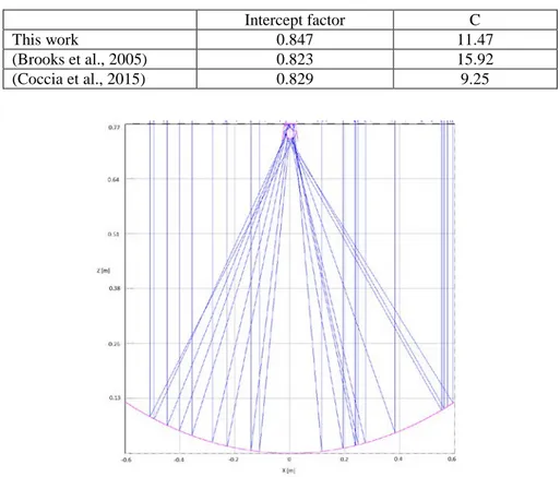
(4) Venegas-Reyes et al. / EuroSun 2016 / ISES Conference Proceedings (2016). Fig. 2: Trapezoidal secondary reflector and receiver. 3. Ray tracing results Ray tracing was carried out with the Soltrace software by considering a Gaussian solar flux distribution and the data contained in Table 1. Figure 3 shows the trajectories of the ray tracing, where one can observe that most of the traced rays fall into the cavity that is formed by the secondary reflector. The intercept factor between the receiver and the primary reflector is 0.847, of which 7.8% of the incident rays in the cylindrical receiver are redirected by the trapezoidal secondary reflector. Table 2 shows a comparison of the intercept factor for different studies, where one can observe that the intercept factor was slightly higher in the proposed collector than in other developed collectors. Tab. 2: Intercept factor for different collectors. This work (Brooks et al., 2005) (Coccia et al., 2015). Intercept factor 0.847 0.823 0.829. C 11.47 15.92 9.25. Fig. 3: Ray tracing paths of circular trough and trapezoidal reflector.
(5) Venegas-Reyes et al. / EuroSun 2016 / ISES Conference Proceedings (2016) Figure 4 shows the radiative flux distribution in the cylindrical receiver. The highest radiative flux density was found at the bottom of the cylindrical receiver (with peak values of approximately 25,000 W/m2). At the top part of the receiver, one can see a slight increase in the radiative flux due to the rays that are redirected by the secondary reflector (with peak values of approximately 5,000 W/m2). It is important to note that in Figure 4, the abscissa is zero at the top of the tube, which means that most of the amount of radiative flux impacts at the bottom part of the receiver.. Fig. 4: Flux distribution in the receiver. The collection efficiency was obtained as a function of the slope error for a specular surface error of 3 mrad. The PTC, the CTC without a reflector, and the CTC with a trapezoidal secondary reflector were compared. It is important to note that, for the circular trough, the receiver was moved so that the opening of the secondary reflector remained in the focus, thus improving the collection efficiency. In Figure 5, one can see that the collection efficiency was greater in both the circular trough without a reflector and in the parabolic trough; however, as the slope error increased, the collection efficiency decreases in a more pronounced manner in these than in the circular trough with a secondary reflector. It is easy to observe that the trapezoidal secondary reflector reduced the optical losses due to the scattering caused by the slope error. For the case in which σ slope = 10 mrad, the collection efficiencies of the PTC and CTC were close to 0.5 while the efficiency for the same slope error for the CTC with secondary reflector was 0.62 (i.e. more than 0.1). This implies that the trapezoidal secondary reflector can minimize the optical losses due to scattering caused by slope errors and other types of dispersion (e.g. profile errors)..
(6) Venegas-Reyes et al. / EuroSun 2016 / ISES Conference Proceedings (2016). Fig. 5: Collection efficiency on the basis of the slope error. Figure 6 shows the collection efficiency as a function of the misalignment error angle for the parabolic trough collector, the cylindrical trough, and the cylindrical trough with a secondary reflector. It can be seen that the decreasing slopes were higher for both the PTC and CTC than for the CTC with a secondary reflector. It is important to note that the optical errors from Table 1 were taken into account to obtain this graph (Figure 6).. Fig. 6: Collection efficiency as a function of the misalignment angle. The collection efficiency appears with a minimal change until the misalignment angle reaches 0.3 degrees; therefore, the tracking error should be less than this value. When the misalignment angle reaches 0.5 degrees, the intercept factor goes down to 0.82, which is relatively close to 0.847 for a 0 degree angle. Even when the misalignment error angle reaches a value of 1, the collection efficiency reaches a value of 0.7 when compared to an approximate value of 0.4 for the other two configurations.. 4. Conclusions Ray tracing showed that the circular trough solar concentrator with a trapezoidal secondary reflector has an acceptable collection efficiency when compared to other devices in literature. A contribution of the present.
(7) Venegas-Reyes et al. / EuroSun 2016 / ISES Conference Proceedings (2016) study is to achieve a collection efficiency comparison between a parabolic trough and a substitute (so to speak), which is the CTC with a trapezoidal secondary reflector. The secondary reflector allows to reduce the losses caused by the slope error, which tends to disperse the reflected rays. At the same time, the secondary reflector allowed for a greater average misalignment error than if one only has the receiver. This demonstrated the utility of this system to minimize the dispersion effects, which improved the collection efficiency and therefore the optical efficiency of the solar concentrator under appreciable error conditions. Finally, the thermal losses of the solar concentrator are expected to be reduced than if one only has the bare receiver; this is thanks to the envelope that is formed by the secondary reflector and the glass of its opening. 5. Acknowledgments To academic technicians of the energy area of CIMAV unit Durango M.Sc. Jorge A. Escobedo-Bretado and M.Sc. Mario Najera-Trejo for their support in ray trace simulations. We thank the support received from: Mexican Center for Innovation in Solar Energy (CeMIE-Sol), Through Project: P13 "Test laboratories for low and medium temperature. Computer-aided laboratory for the design and integration of solar thermal systems". 2013-02 Sustainable Energy Federal Research Fund: CONACYT – SENER, for the development of this work.. 6. References Abbas R., Montes M.J., Rovira A., Martínez-Val J.M. Parabolic trough collector or linear Fresnel collector? A comparison of optical features including thermal quality based on commercial solutions. Solar Energy 124 (2016) 198–215. Brooks, M. J., Mills, I., Harms, T. M. (2005), Design, construction and testing of a parabolic trough solar collector for a developing-country application, Proceedings of the ISES Solar World Congress, Orlando, Florida, pp. 6-12. August 2005. Chemisana D., Ibáñez M., Rosell J.I., 2011. Characterization of a photovoltaic-thermal module for Fresnel linear concentrator. Energy Conversion and Management. 52, 3234–3240. Chen Y.T., Ho T.H. Design method of non-imaging secondary (NIS) for CPV usage. Solar Energy 93 (2013) 32–42. Cheng Q., Chai J., Zhou Z., Song J., Su Y., 2014. Tailored non-imaging secondary reflectors designed for solar concentration systems. Solar Energy. 110, 160–167. Coccia G., Di Nicola G., Sotte M. Design, manufacture, and test of a prototype for a parabolic trough collector for industrial process heat. Renewable Energy 74 (2015) 727-736. Kalogirou S. A. The potential of solar industrial process heat applications. Applied Energy, 76 (2003) 337– 361. Hecht, E., 2000. Optics. Addison Wesley, Madrid, pp.184-187. Mills D. R., 1995. Two-stage solar collectors approaching maximal concentration. Solar Energy. 54, 41-47. Rodriguez-Sanchez D., Rosengarten G., 2015. Improving the concentration ratio of parabolic troughs using a second-stage flat mirror. Applied Energy. 159, 620–632. Singh P. L., Ganesan S., Yadav G. C. Performance study of a linear Fresnel concentrating solar device. Renewable Energy 18 (1999) 409-416. Spirkl W., Ries H., Muschaweck J., Timinger A., 1997. Optimized compact secondary reflectors for parabolic troughs with tubular absorbers. Solar Energy. 61, 153–158. Venegas-Reyes E., Jaramillo O. A., Castrejón-García R., Aguilar J. O., Sosa-Montemayor F., 2012 Design, construction, and testing of a parabolic trough solar concentrator for hot water and low enthalpy steam.
(8) Venegas-Reyes et al. / EuroSun 2016 / ISES Conference Proceedings (2016) generation. Journal of Renewable and Sustainable Energy. 4, 053103. Zheng H., Feng Ch., Su Y., Dai J., Ma X., 2014. Design and experimental analysis of a cylindrical compound Fresnel solar concentrator. Solar Energy. 107, 26–37..
(9)
Figure


Documento similar
1. S., III, 52, 1-3: Examinadas estas cosas por nosotros, sería apropiado a los lugares antes citados tratar lo contado en la historia sobre las Amazonas que había antiguamente
MD simulations in this and previous work has allowed us to propose a relation between the nature of the interactions at the interface and the observed properties of nanofluids:
In the previous sections we have shown how astronomical alignments and solar hierophanies – with a common interest in the solstices − were substantiated in the
While Russian nostalgia for the late-socialism of the Brezhnev era began only after the clear-cut rupture of 1991, nostalgia for the 1970s seems to have emerged in Algeria
current number of electrons in the simulation is greater than N times the initial number, the simulation stops predicting a multipactor occurrence.. Conversely, if the number
What is perhaps most striking from a historical point of view is the university’s lengthy history as an exclusively male community.. The question of gender obviously has a major role
The losses due to the tunnelling trough the optical barriers formed by the tracks are evaluated by computing the power of the fundamental mode that remains inside the structure af-
3) A North African depression. A system of three centers of pressure controls the flows affecting southern Europe and the Mediterranean basin: a trough placed over northern
