TítuloModeling of the human vestibular system and integration in a simulator for the study of orientation and balance control
8
0
0
Texto completo
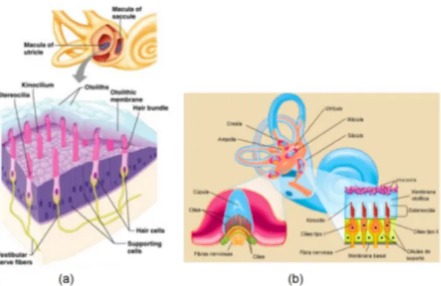
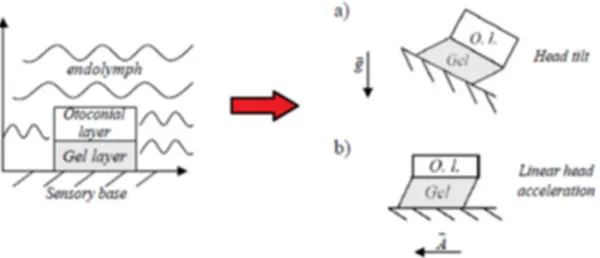
(2) 2.2. MATHEMATICAL MODEL OF SEMICIRCULAR CANALS. The model used in this work is the semicircular canals dynamic model proposed in [6]. They obtained the model for an individual semicircular canal ignoring the fluid communication with the two associated canals given by the following mechanical behaviour: m. dQ d2 Q +c + kQ = f, dt2 dt. (1). where Q is the displaced volume of endolymph, m is the mass of the fluid contained in the canal, c describes the damped viscous effect in the conduit, k is the stiffness of the cupula, and f is an inertial force.. Figure 1: Physiology of human ear: (a) macule c of the utricle and the saccule ⃝2004 Pearson Education, Inc., publishing as Benjamin Cummings (b) outside and inside of the semicircular canals c ⃝1997 Encyclopædia Britannica, Inc. Going into the Laplace domain and making the corresponding unit changes, the following transfer function can be obtained: Tssc (s) = 2.1. BIOLOGICAL BACKGROUND. ds/m Q(s) )( =( ω(s) s+ s + τ11. 1 τ2. ),. (2). where d is an inertial force coefficient, and τ1 and τ2 are the time constants of the system. This transfer function relates the volume displaced by the cupula (in cm3 ) with the angular velocity of the head (rad/s). The values of m, d and of the time constants are shown in Table 1.. The vestibular system is a cuboid cavity located in the inner ear, specifically in the center of the bony labyrinth. It is formed by the vestibule and the semicircular canals. Inside the vestibule there are two membranous structures [1]: the utricle and the saccule. In the utricle and saccule there are peripheral receptor organs called macules (Fig. 1(a)), which are composed of sensory ciliated receptor cells, which are covered by a horizontal membrane on which there is a series of calcium carbonate crystals that receive the name of otoliths, which are very susceptible to linear accelerations or decelerations in the three planes of space.. Table 1: Parameters of the model of the semicircular canals. Parameter k m d τ1 τ2. On the other hand, the semicircular canals are three, one horizontal and two vertical [1]. They are cylindrical tubes that form two thirds of a circumference and are oriented in the three planes of space, so that the plane of each of them forms with the other two a 90◦ angle (Fig. 1(b)). The semicircular canals are filled with a pristine fluid called endolymph. The stimulation factor of the semicircular canals are angular accelerations, either by rotation of the head or rotation of the whole body.. 2.3. Value 6.8 Gpa/m3 1070 g/cm4 0.76 g/cm 13.2 s 6 ms. Description stiffness of the cupula coefficient mass of the fluid contained in the canal inertial force coefficient time constant time constant. MATHEMATICAL MODEL OF OTOLITHS. The first model of otoliths was proposed by Meiry in 1966, with which velocity was obtained from a velocity stimulus. Later, Grant and Cotton introduced an additional damping to emulate the mechanical behaviour of the viscoelastic gelatinous layer. They considered the otoliths as a secondorder mass damping system, where the otoconia layer was modeled as a rigid solid. The gel layer was modeled as a viscoelastic isotropic material, and the endolymph was modeled as a Newtonian fluid with uniform viscosity (see Fig. 2). Refer to [7] for more details.. The semicircular canals lead into the vestibule at its two extremes, one of which, called the ampulla, has a double diameter and the other is where the recipients of angular movement, the ampular crests, reside. These crests are supported by the support cells and covered by a gelatinous substance rich in mucopolysaccharides, called the cupula.. Later on, Hosman realized that the previous model did not have an easy implementation due to. 637.
(3) canals (specifically by the lateral canal) in such a way that a displacement of the endolymph fluid will occur. 3.1. The kinematic model is due to the fact that, while the chair rotates, it is admitted that the person can turn his head on the three axes X, Y , and Z (roll, pitch and yaw) (Fig. 3(b)) whose rotation angles are α, β, and γ, respectively. This effect will be added to the effect produced by the rotation of the chair, whose angle of rotation is δ.. Figure 2: Schematic diagram of the performance of the otolith organ: (a) Stimulus inclination of the head (b) Inertial stimulus. Image extracted from [7]. To work with this kinematic model we will consider the reference systems shown in the Fig. 4. The aim is to obtain the components of the angular acceleration vector (which is transformed at an angular velocity prior to being introduced in the semicircular canal model) and the components of the linear acceleration vector, both of which need to be expressed in the reference system R0 (terrestrial system or reference), knowing the angular velocity vector of the chair in R1 and the angular velocity vector of the head in R2.. the fractional exponent and therefore proposed a simplification to the model that would be refined by Telban and Cardullo more recently, resulting in the following transfer function [9] G(s) =. AF R(s) 33.3 (10s + 1) = , F (s) (5s + 1) (0.016s + 1). (3). that relates the transmission of nerve signals from the otolith dynamics (afferent firing rate, AFR) with a gravito-inertial force f , or the linear acceleration (m/s2 ). This acceleration will be the one obtained from the kinematic model in addition to the linear acceleration that is considered to have the head of the person due to linear movement, if it is considered.. 3. KINEMATIC MODEL. THE 3-DOF SIMULATOR. Figure 4: Reference systems: system R0 (O, X0 , Y0 , Z0 ) (terrestrial system), system R1 (O, X1 , Y1 , Z1 ) (system associated with the chair), system R2 (A, X2 , Y2 , Z22 ) (system associated with the head), system R3 (B, X3 , Y3 , Z3 ) (system associated with semicircular canals if they are not considered orthogonal) The angular velocity vector of the rotation chair in R1 is ω̄1 = (0, 0, δ̇). Then, the angular velocity of the chair can be calculated in R0 by means of. Figure 3: Illustration of the simulator: (a) a person is sitting on a platform that rotates with a certain angular velocity with the sense of balance assimilated by the semicircular canals (b) details of turns of the head on the three axes: roll, pitch and yaw. ω̄1/0 = Mδ ω̄1 , ( where Mδ =. cos δ − sin δ 0. sin δ cos δ 0. 0 0 1. (4) ) is the transfor-. mation matrix of the two reference systems.. This section describes the simulator developed in this work based on the illustration shown in Fig. 3(a). As can be seen, it consists of a person sitting on a chair or platform that rotates with a certain angular velocity. This person experiences a stimulation of the sense of balance, rotation that will be assimilated by the semicircular. The movements of the head are defined by the angular velocity vector in R2, i.e., ω2 = (α̇, β̇, γ̇). Then, the angular velocity of the head is calculated in R0 as ω̄2/1 = Mα Mβ Mγ Mδ ω̄2 ,. 638. (5).
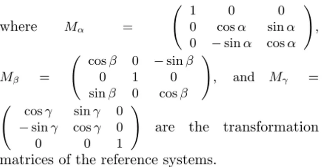
(4) (. where. Mα. =. ( Mβ. (. =. cos γ − sin γ 0. cos β 0 sin β sin γ 0 cos γ 0 0 1. 0 1 0. ). ). 1 0 0 0 cos α sin α , 0 − sin α cos α ) − sin β 0 , and Mγ = cos β. 3.2. IMPLEMENTATION IN MATLAB/SIMULINK. Figure 5 shows the appearance of the 3-DOF robot in Simulink. Its implementation can be divided into two parts: the kinematic model of the robot including the VS, and the postural control. Details of each part are given next.. are the transformation. matrices of the reference systems. The total angular velocity vector is obtained in R0 by ω̄2/0 = ω̄2/1 + ω̄1/0 , (6) adding the contributions of the angular velocity of the head and the angular velocity of the chair, both expressed in R0. Likewise, to obtain the angular accelerations in the R0 system, we operate in the same way as before. Adding the two contributions, the total angular acceleration vector in R0 is given by ¯ 2/0 = ω̇ ¯ 2/1 + ω̇ ¯ 1/0 . ω̇. Figure 5: Appearance of the 3-DOF robot in Simulink. (7). Since the kinematic model admits the possibility of considering non-orthogonal semicircular canals (reference system R3), a last transformation can be made to express the angular accelerations with this non-orthogonal orientation. This transformation can be expressed by ¯ B2/1 = Mϕ Mθ Mψ ω̇ ¯ 2/0 , ω̇. 3.3. The block diagram of the kinematic model of the robot with the VS is shown in Fig. 6. As can be observed, it is composed by:. (8). • The subsystem Semicircular canals simulates the kinematic model explained in the previous section. The components of the angular acceleration vector resulting from this subsystem, either expressed in the system R0 (consideration of orthogonal semicircular canals) or in the system R3 (consideration of non-orthogonal semicircular canals), are integrated to obtain the angular velocity vector and subsequently each component of this vector is introduced into the transfer function (2). As a result, the volume of endolymph displaced by the cupula in the three semicircular canals (posterior, anterior and lateral) is obtained.. where Mϕ , Mθ , and Mψ are the transformation matrices for the system R3, with ϕ, θ and ψ represent the Euler angles defining the normal to the plane of each canal (lateral, posterior and anterior). The values of these angles are shown in Table 2. Table 2: Euler angles that define the perpendicular of each canal. Canal Anterior Lateral Posterior. ψ (rad) 2.212 2.336 0. β (rad) 0.177 0 −0.331. Kinematic model with vestibular system. ϕ (rad) 0 −0.274 0.038. The angular movements also give rise to components of linear acceleration (A), which contribute to stimulate the otoliths. The terms that make up the linear acceleration vector at point B (origin of the R3 system, where the VS is located) are expressed as. • The linear acceleration vector that will be introduced in the otolith transfer function (3) is obtained by the subsystem Utricle and saccule.. ¯ ¯ 1/0 × AB ĀB2/0 = ĀB2/1 + ω̇ (9) ( ) ¯ +ω̄1/0 × ω̄1/0 × AB + Ācoriolis , 0 ¯ = 0.03 (in m), ĀB2/1 = ω̇ ¯ 2/1 × where AB 0 ¯ and Ācoriolis is the acceleration due to the AB, Coriolis acceleration term.. The connection between the two main blocks is due to stimulation of the VS: the outputs of the kinematic model of the robot, namely, angular velocities and linear accelerations, are the inputs to the dynamic model of the VS. This, in turn, is composed by the model of semicircular canals, which will be stimulated by the angular velocities, and the one corresponding to otoliths (otolithic. 639.
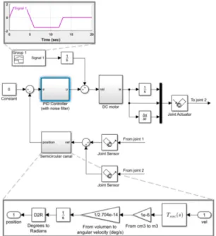
(5) The control system of the robot deals with a closed-loop with a PID controller with noise filter for each DOF (control position), as shown in Fig. 7. It can be seen that the reference is 0 rad in the three degrees of freedom. Likewise, the rotations of the other joints are added as a disturbance in the system in every control loop. It should be noticed that:. macula), which will be stimulated by the linear accelerations.. 1. The subsystem Semicircular canal is used as a sensor to measure the angular position of the respective DOF. 2. A disturbance is added to the loop to emulate the movement of the head. Figure 6: Kinematic model with VS in Simulink. 3. Although the DC motor model requires an angular velocity as input, it also works by introducing an angular position as input. This is because the angular velocity which is going into the semicircular canal model is obtained from a Simscape block (joint sensor), which provides the angular velocity of the joint (in rad/s).. It should be remarked that it is possible to choose if the person experiences a movement of translation, i.e., another vector of linear acceleration will be added to the linear acceleration vector obtained from the angular movement (the one that has been calculated in the subsystem Semicircular canals). 3.4. 4. The control loop is the same in the case of the degree of freedom in the rotation over X, Y and Z, except that in the rotations over X and Y only the disturbance of the control signal must be compensated (movement of the robot in those axes). Hence, in this case there is no other contribution to the rotations (the rotation of the platform only affects to the rotation over Z).. Control of the robot. The robot is on a rotating platform and in turn can make three turns emulating the turns of the head (roll, pitch and yaw). For this purpose, it has two joints and, in turn, the head allows the relative rotation with the pole where it is held. The appearance illustrated in Fig. 5 is obtained by using blocks of Simmechanics from creating each part in Solidworks.. 4. SIMULATIONS. This section shows the simulations of the 3-DOF robot developed in Simulink. For illustration purposes, results of the kinematic model with the VS are firstly given. Then, the corresponding to the whole model are discussed. For simulations, the values of the proportional, integral and derivative gains of the PID controllers were tuned empirically. 4.1. KINEMATIC MODEL WITH VESTIBULAR SYSTEM. In this section, several simulations of the model in Simulink in Fig. 6 will be made for the angular velocity of the chair/platform stimulus and the head rotation stimulus. Figure 8 illustrates the volume displaced in the semicircular canals when only the chair moves with a constant angular velocity of 1.7 rad/s, starting at 1 second. For the orthogonal consideration (Fig. 8(a)), it is clear that only the lat-. Figure 7: Closed-loop diagram to control the angular position of each joint of the robot in Simulink. 640.
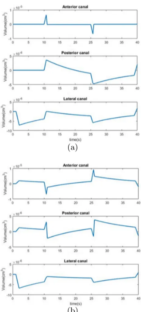
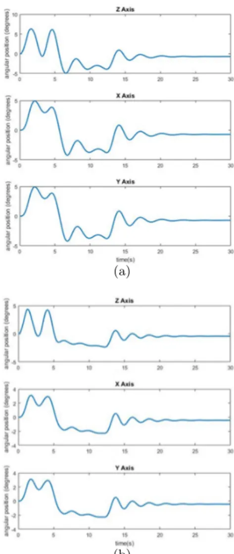
(6) gravity. Furthermore, if we now consider that the head experiences different rotations in the different axes of rotation at the instants t = 10 s and t = 25 s, the displaced volumes in the semicircular canals are shown in Fig. 10 for the orthogonal and nonorthogonal cases. For the former (Fig. 10(a)), it can be stated that each semicircular canal is stimulated with the component of the angular acceleration vector that corresponds to its respective orthogonal axis (anterior with the component Y ; posterior with the component X; lateral with component Z). In addition, the lateral canal first suffers volume displacement due to the angular acceleration produced by the chair in the head and then that of the turn over the Z axis (yaw) of the person’s own head at instants t = 10 s and t = 25 s. In the consideration of non-orthogonal canals, as can be observed from Fig. 10(b), a volume displacement is produced in the three canals with the movement of the rotating chair, which is obviously greater in the lateral canal. However, at the rotation instants, the anterior and posterior canals begin to experience a larger volume displacement that is obviously caused by the component of the angular acceleration vector of the head that coincides with the orthogonal axis of the respective semicircular canal. The lateral canal suffers a displacement of volume very similar to the case of orthogonal canals.. (a). (b). Figure 8: Volume displaced in the semicircular canals: (a) orthogonal case (b) non-orthogonal case. 4.2. SIMULATOR. A simulation of the whole model of the robot will be carried out and the error signals will also be obtained in terms of angular position (degrees).. eral canal is stimulated since the rotation of the chair stimulates the rotation on Z axis of the head (yaw). For the non-orthogonal case (Fig. 8(b)), the lateral canal suffers the greatest stimulation. However, both the anterior and posterior canal also suffer a volume displacement, although less than the lateral and in a different direction.. The angular velocity of the platform can be seen in Fig. 11(a) and the angular velocities of the robot turns over the X, Y , Z axes (disturbances) are equal and have the form shown in Fig. 11(b). Simulation results are obtained for two different control cases, in which only the integral part of the PIDs will be changed. Let subscripts X, Y , and Z denote the controller applied to the DOF corresponding to X, Y , and Z axes, respectively. The cases considered are: case 1) the controller parameters are KiX,Y = KiZ = 5; and case 2) the controller parameters are KiX,Y = KiZ = 8. In both scenarios, KpX,Y,Z = 2, KdX,Y,Z = 50, and NX,Y,Z = 50.. Regarding otoliths, the behaviour is shown in Fig. 9 with and without considering translational movement. For the latter (Fig. 9(a)), it can be seen that the greatest stimulation in terms of AFR is on the Z axis due to the acceleration of gravity, being on the X and Y axes negligible by comparing the order of magnitude. Likewise, when considering translational movement with a linear acceleration vector whose components in the three axes have a trapezoidal function starting at 3 seconds and ending at 7 seconds with a maximum value of 1 m/s2 , it can be observed from Fig. 9(b) that now the stimulation on the X and Y axes is much greater due to the acceleration. The greatest stimulation is still on the Z axis because of. Figure 12 shows the error when controlling the robot with the different PIDs. In Fig. 12(a), it can be observed how the controller tries to take the error to 0 degrees and when the turns end it gets the error has a stable value, although there is a small stationary error due to disturbances the introduced. The signal on the Z axis is obtained by. 641.
(7) (a) (a). (b) (b). Figure 10: Volume displaced in the semicircular canals considering rotations in the head: (a) orthogonal case (b) non-orthogonal case. Figure 9: AFR on the X, Y , Z axes of otoliths: (a) with no translational movement (b) with translational movement. of the robot. adding the angle rotated by the platform plus the angle rotated by the robot head (which will have opposite sign), since this DOF must compensate the rotation of the platform. The result of this sum should be zero or very close to zero. But for the second scenario, a lower stationary error is obtained, as well as lower overshoot (see Fig. 12(b)).. 5. In accordance with the role in humans, simulation results in the MATLAB/Simulink environment were given to show the importance of the VS to control the orientation of the head in space (roll, pitch and yaw). The simulator was controlled by a proportional-integral-derivative (PID) with noise filter for each DOF. With regard to possible future work lines, the most immediate would be the construction of the robot and the use of the model that has been developed to provide the control signals to real electric motors. The semicircular canals can be built e.g. by a 3D printer and fill them with a liquid with properties similar to the endolymph. Thus, the displaced volume of liquid and hence the angular velocity could be measured.. CONCLUSIONS. This paper has presented the balance and orientation control of a three degree-of-freedom (DOF) simulator that emulates a person sitting in a platform based on the human vestibular system (VS) to regulate and stabilize gaze during head motion. The VS was essentially modelled through the behavior of the semicircular canals and otoliths in the presence of stimuli, i.e., linear and angular accelerations/velocities derived by the turns experienced by the robot head on the three Cartesian axes. The semicircular canal was used as the angular velocity sensor to perform the postural control. Acknowledgment This work has been partially supported by the FEDER Funds (Programa Operativo FEDER. 642.
(8) Figure 11: Reference angular velocities for the (a) platform (b) X, Y , Z axes of the simulator. (Notice that the scale of y-axis is not the same.) de Extremadura 2014-2020) through the grant “Ayuda a Grupos de Investigación” of the Junta de Extremadura. (a). References [1] Terry D.Fife. Handbook of Clinical Neurophysiology, volume 9, chapter Overview of anatomy and physiology of the vestibular system, pages 5–17. Elsevier, 2010. [2] Egidio Falotico, Nino Cauli, Przemyslaw Kryczka, Kenji Hashimoto, Alain Berthoz, Atsuo Takanishi, Paolo Dario, and Cecilia Laschi. Head stabilization in a humanoid robot: models and implementations. Autonomous Robots, 41(2):349–365, 2017. [3] Ildar Farkhatdinov. Modelling verticality estimation during locomotion. PhD thesis, Institut des Systémes Intelligents et de Robotique, Univerty of Sorbonne, 2013.. (b). Figure 12: Error signal on each axis for different PID controllers: (a) Case 1 (b) Case 2. [4] Thomas Mergner, Georg Schweigart, and Luminous Fennell. Vestibular humanoid postural control. Journal of Physiology-Paris, 103(3):178–194, 2009.. [8] Karim A. Tahboub. Biologically-inspired humanoid postural control. Journal of Physiology-Paris, 103(3):195–210, 2009.. [5] F. Patane, F. C. Laschi, H. Miwa, E. Guglielmelli, P. Dario, and A. Takanishi. Design and development of a biologicallyinspired artificial vestibular system for robot heads. In Proceedings of 2004 IEEE/RSJ International Conference on lntelligent Robots and Systerns, pages 1317–1322, 2004.. [9] Robert J. Telban and Frank M. Cardullo. Motion cueing algorithm development: Humancentered linear and nonlinear approaches. Technical report, State University of New York, 2005. [10] Vishesh Vikas and Carl Crane. Bioinspired dynamic inclination measurement using inertial sensors. Bioinspiration & Biomimetics, 10:036003, 2015.. [6] R. D. Rabbitt, E. R. Damiano, and J. W. Grant. The Vestibular System, chapter Biomechanics of the Semicircular Canals and Otolith Organs, pages 153–201. Springer, 2004.. c 2018 by the authors. ⃝ Submitted for possible open access publication under the terms and conditions of the Creative Commons Attribution CC-BY-NC 3.0 license (http://creativecommons.org/licenses/by-nc/3.0/).. [7] Pierre Selva. Modeling of the vestibular system and nonlinear models for human spatial orientation perception. PhD thesis, Institute of Aeronautics and Space, University of Toulouse, 2009.. 643.
(9)
Figure
+4

Documento similar