Escuela de Ingenier´ıa en Electr´
onica
Improvement of small satellite’s software design
with build system and continuous integration
tools
para optar por el t´ıtulo de
Ingeniero en Electr´
onica con ´enfasis en sistemas
empotrados
con el grado acad´emico de
Maestr´ıa
Allan Granados
Contents
1 Introduction 8
1.1 Previous work focus on small satellites . . . 9
1.2 Problem statement . . . 11
1.3 Proposed solution . . . 13
1.3.1 Proposed development . . . 13
2 Software development approaches for small satellites 15 2.1 Software methodologies used for satellites design . . . 15
2.2 Small satellite design and structure . . . 17
2.3 Central computation system in satellites. Homogeneous and Het-erogeneous systems . . . 18
2.4 Different approach on software development for small satellites . 20 2.4.1 Software development: Monolithic approach . . . 20
2.4.2 Software development: Development by component . . . . 21
2.5 Open Source tools on the design and implementation of software satellite . . . 23
3 Integration of build system for small satellite missions 24 3.1 Build systems as an improvement on the design methodology . . 24
3.1.1 Yocto build system . . . 29
4 Development platforms 32 4.1 Beagleboard XM . . . 32
4.2 Pandaboard . . . 35
4.3 Beaglebone . . . 38
5 Design and implementation of the construction system 41 5.1 Construction System . . . 41
5.1.1 The hardware independent layer: meta-tecSat . . . 42
5.1.2 The hardware dependent later: meta-tecSat-target . . . . 43
5.1.3 Integration of the dependent and independent hardware layers in the construction system . . . 44
5.1.4 Adding a new recipe to a layer . . . 46
5.2 Continuous integration system in the tecSat project . . . 46
5.2.1 Integration of Jenkins with tecSat Project . . . 47
6 Development and results using the construction system 53 6.1 Construction system information recollected from the build system 53 6.1.1 Construction time . . . 53
6.2 Required size for construction . . . 55
6.3 Stability of the construction system . . . 55
6.4 Application development of a hardware independent application . 56 6.4.1 Color space conversion, RGB to YCbCr . . . 57
6.4.2 Development of a hardware independent recipe . . . 58
6.4.3 Deployed images for different targets . . . 58
6.4.4 Result of RBG to YCbCr using the GPP . . . 59
7 Future Work 61 7.1 Support of DSPLINK API . . . 61
7.1.1 Validation test on the DSP for the Beagleboard XM . . . 63
7.2 RBG to YCbCr using the DSP . . . 64
List of Figures
1.1 Software development methodology for space exploration projects 12
1.2 Proposed solution for software development on small satellites . . 13
2.1 Cubesat design example1 . . . . 17
2.2 Monolithic development2. . . . 21
2.3 Development by component3 . . . . 22
3.1 The Y chart approach with the different development stages4 . . 26
3.2 Yocto Project Development Environment5 . . . . 30
3.3 Building an Image with Yocto6 . . . . 30
4.1 Beagleboard XM7. . . . 33
4.2 Pandaboard development board8 . . . . 35
4.3 Pandaboard general block diagram9 . . . 37
4.4 Beaglebone Black10. . . 39
5.1 Directories of the construction system11 . . . 42
5.2 Layers inside the build system12 . . . . 45
5.3 Principal Jenkins panel for tecSat project13 . . . . 48
5.4 Principal Jenkins panel for tecSat project from a cellphone14 . . 49
5.5 Configuration for the tecSat SDK Jenkins job . . . 50
5.6 Console output for the tecSat image beagleboard Jenkins job15 . 51 5.7 Jenkins artifacts on a build16 . . . . 52
6.1 Constructions statistics of the different Jenkins jobs17 . . . . 54
6.2 Color space transformation in the Beagleboard XM. A) Base im-age. B) Octave representation of algorithm. C) Conversion by the GPP18. . . . 59
7.1 DSPLINK software architecture19. . . 63
7.2 Design representation for the rgb2ycbcr dsp application20 . . . . 65
List of Tables
3.1 Comparison between different build systems21 . . . 28
4.1 Beagleboard XM features22 . . . . 34
4.2 Pandaboard ES features23 . . . . 36
4.3 Beaglebone Black features24 . . . . 40
6.1 Construction time for every platform . . . 54
6.2 Required size of the construction system for each platform . . . . 55
6.3 Footprint of the different images (minimum packages required) . 59 6.4 Color space transformation on the GPP of the Lena image . . . . 60
6.5 Color space transformation on the GPP . . . 60
7.1 Result of DSPLINK examples . . . 64
Abstract
The space exploration is a field that requires the interconnection of different research disciplines including medicine, biology, physics and of course electron-ics and embedded systems. Because of this integration of different disciplines, the development of software for this system can become a challenge. Because of this, it is important to have a common way to introduce pieces of software without alter or risk the deployment of the whole system. This work is focus on the design, development, and result data recollection of a deployment system of software focus on the space exploration field. It implement the Yocto project as its main construction system, by which the user can include and/or customize different pieces of software reducing the dependencies between different mod-ules. It is also part of this work, the implementation of a continuous integration system (CI), in charge of reviewing and reporting the status of the final de-ployed image. This CI system also recollects important information about the construction of the deployed image as well as its stability during the project development. Results of the deployed images were tested on different develop-ment platforms.
Keywords:
Yocto, Linux, OBC, SDR, UML, Stakeholder, Continous Integration, Jenkins.
Chapter 1
Introduction
The space exploration is the field which study outer space by using scientific equipment. It requires the interconnection of different research disciplines in-cluding medicine, biology, physics and of course electronics and embedded sys-tems. Space exploration is not new, for centuries the human race have dreamed about space flights and what is beyond. Since antiquity the Chinese used rock-ets for ceremonial and military purposes, but it was not until the last hundred years when the efforts were focus into a new frontier, the space beyond the Earth. Overcome the Earth gravity was not an easy task, but it led to an inves-tigation race in the early 20th century between powerful nations as Germany, Russia and the United States. It was until October 4, 1957, when the Soviet Union accomplish the first successful orbital launch, the first satellite, called Sputnik 1. The success of the Soviet satellite program, led to an escalation of their competitors in order to achieve the same results. Further development in the related fields help to improve the scope of the different missions, which in the end, led to many scientific discoveries, including important research in the electronics field and communications. But why is space exploration so impor-tant?. Space exploration is important because as humans it helps to address fundamental question about our existence, our place in the Universe and the history of the universe around us. It help to expand our technological advance in different fields and speed up the communication of this advances to all human race.
The space exploration goes from sending a remote controlled or autonomous device to outer space, to planetary exploration with manned missions. The present work focus on the devices placed into orbit in order to recollect and transmit information, commonly known as satellites. Because outer space is a hazardous environment, the exploration become a difficult task. The imple-mentation of low cost, low power and simple embedded systems becomes an ideal solution, reducing the risk of accidents and speeding up the recollection of data. The construction of such devices become an important topic, which comprehend hardware and software development. The methodologies and im-plementation of the software for satellites are investigated in the present work,
seeking for an implementation which improve the quality of software and speed up the development process.
The development of software for small satellites is a challenge, it includes the budget of the project, the experience of the team members, the development time and many others [9]. This challenges combines with the need of stable, efficient and reliable software, making the task even harder. Because of this, the need for a well defined design, development and construction process is required. It is a common problem on the small satellites projects, the lack of reusable and portable software, which usually is wrap in a monolithic design, making it hard to be of use in other missions in order to speed up the development or even take advantages of experience obtained in the past. If the design and development method is defined and consistent, it will help to accurate schedule the project, take advantages of the experience and reuse pieces of stable and efficient software. A good and accurate schedule in spacial exploration projects can result in the execution of the project or its cancellation, specially in a field were different investigation groups are racing for the same objective[18].
In order to achieve a consistent design and development process, the use of well know tools and methodologies can be incorporate in the project. These tools can be from the Open Source community or licensed product for a vendor. Is a common fear around developers that sometimes, good stable code is only found on commercial software, while open source code fluctuates with latest re-leases and improvements [24]. In reality, stable and reliable packages, tools and code can be found in either commercial or Open Source products, it depends on the developers integrating the product, to select those projects which demon-strate its stability. An example of a Open Source project which has proven its stability is the Yocto project. It balances between the dynamics of the Open Source cooperative development and the commercial requirements of time line, cost effective and stable releases [24]. This work present the development of a software construction project, using Yocto as a central build system. It takes advantage of the layer methodology to separate different packages in different levels of abstraction, where platform dependent and independent code can be separate in order to increase re-utilization. A central configuration system is designed and implemented in order to fetch, configure and construct the soft-ware in a way users not familiar to build systems or Yocto can use it and obtain an image or an SDK for a specific platform in a easy way.
1.1
Previous work focus on small satellites
The space exploration projects has rapidly increase in the last few years. Several space exploration missions has been developed using small satellites. Those mis-sions are designed to recollect important data, not only about space, but about the project development itself. The idea is to give feedback about challenges, opportunities and what to have into account for a successful mission.
family processor for the OBC, which is a 32 bit synthesizable VHDL pro-cessor core from SPARC V8 architecture. The design of the project is created on a high level graphical model to capture the different compo-nents, which finally are traduced into ADA. This project focuses on the analysis of the WCET (Wort’s Case Execution Time) for the performance of the system. It shows the power in the uses of a VHDL specialized processor for a space exploration mission and its flexibility.
• ION Project [9]: The ION satellite are a two micro-satellite constructed by the University of Illinois. The main purpose of the project is to provide a large interdisciplinary educational project for engineer students. On this project is researched the use of off of the shell components and the difficulties on the satellite designs like cost and development time. This project implements several external components like cameras and other sensors and was an evolving project giving more than one implementation of a satellite. It is shown how the integration of different components is a very important part of the development and how it can affect the release for the final satellite.
• RinconSat [13]: This project was developed for the study of a RTOS for small satellites by the University of Arizona. The OBC used was base on a PIC16C77 micro-controller from Microchip Corporation. This project reveals the OS limitation base on the available memory, and for that reason a simple serial scheduling process was supported. Although the development time of the project was short and the cost of the satellites was very low, the hardware limitations reveal the lack of scalability for future missions using this satellite design.
• DANDE [18]: Started as a student developed nano-satellite project by the Colorado Space Grant Consortium, its main mission was to study the effects of space weather and atmospheric drag on a small satellite platform. They bring the use of a more complex OS, the uClinux version for micro-controllers. However this version of Linux brings the need for good data and program separation, because its designed for systems where a memory management unit (MMU) its not present. They implement a simple single control loop, where a process checks the memory integrity in case of cosmic rays memory corruption. Its shows the space exploration community the advantages of a more complex OS implementation and how the problems like data corruption may be overcome.
• USS Langley [2]: The project objective was to demonstrate the ability to host a web server in a small satellite using TCP/IP internet protocols and be accessible to any internet user. In addition, testing space based net-works against terrestrial netnet-works was intended. This project is specially interesting because of the use of a Beagleboard TI development board as the host for the web server. The developers of the project choose the Bea-gleboard because of its small from factor, customizability and low power requirements. However the kernel of the board was a 2.6 version, been a very old kernel version. In addition, the project integrate several process-ing units, each one with a specific task, which increment the complexity and power consumption. For example, the Beagleboard, hosting only the web server, consumed 600mA, increasing the power requirements of the small satellite.
Each one of the projects mention before, recollected important data and invaluable experience, however, the implemented software has proven to lack in scalability and in many cases was impossible to adapt into further missions because of its platform dependent nature and the monolithic design of the whole software in the project.
1.2
Problem statement
The design and implementation of software for satellites, even for small satellites, is a time consuming and multi-disciplinary process, which require great effort [15]. The demand for more complex functionality arises day to day, in company of contractions on the development schedules, seeking faster times to market [31]. In addition, the available resources, money, equipment and personal, de-termine the development time required [19]. Hence, a good methodology and development process is required.
In the development of a space exploration projects, in many cases, the de-tailed specification of the satellite, or the scope of the mission are not known beforehand, it is necessary to be reverse engineered from the capabilities of the components and the available development vehicles [9]. In other projects, a well defined scope is defined and traduced into a System Requirement Specification (SRS), where the expected behavior and the needs are well documented [26]. On both cases, it is necessary to study the limitations of the design and the development process[13]. If the development process is not flexible enough it can not be re-used or adapted in the presence of changes. The lack of flexibility will require extra development time for its adaptation.
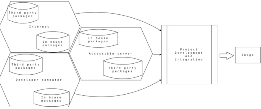
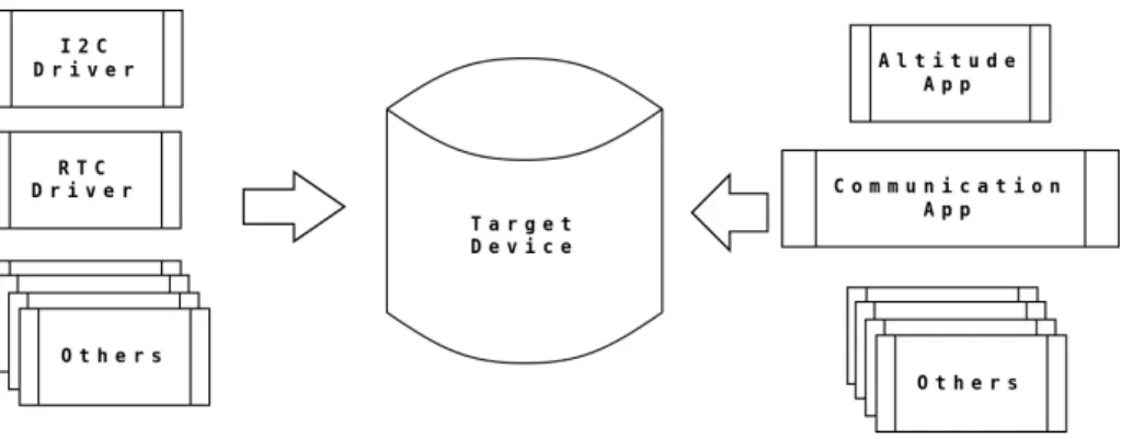
increase of the software complexity and the occurrence of system errors may be present[18], more importantly when new software is incorporated. Therefore, the importance on the development software planning is reflected, which need to account for the possibility of future work [14], incorporate new technology and making development advances for future missions. The actual software de-velopment for space exploration mission is shown in figure 1.1.
Figure 1.1: Software development methodology for space exploration projects
As shown in figure 1.1, for a specific space exploration project, many soft-ware sources are incorporated. However, the construction and integration use to be project specific, showing troubles in scalability and software re-utilization. In addition, when the scope of the project is achieved, the development and in-tegration process is usually discarded. Its shown the necessity of a development process capable of fetching from the available software sources and construct a customize image for the satellite, but with the capability to be use in future space exploration process and incorporate new software.
To recapitulate, several problems on the actual development for small satel-lites are found, which can be solve by the incorporation of a scalable and reusable development methodology.
1. The increase of the software requirements for small satellites.
2. Increase on the time for software components integration.
3. Reduce of the cost and development time of a project.
4. Reduce the learning curve for new developers.
5. Breach between the design methods and the software implementation.
1.3
Proposed solution
Many challenges have been stated, revealing the hard task of working on the design and development of the small satellite software. Knowing these chal-lenges, is important to structure and implement a development methodology which can be easy to implement by developers, adopt currently available tech-nologies, easy to adapt to the current production process and improve scalability and re-usability. Because of this, the implementation of a construction system, using the Yocto project as its internal build system is propose to be incorpo-rate into the development process for small satellites. This construction system seeks to separate into different layers of abstraction different software packages, improving modularization and ease the re-usability of software. The use of a continuous integration system like Jenkins is added into the project. The con-tinuous integration system is intended to collect information about the project, check the stability by schedule constructions and ease the access for users to deployed images.
1.3.1
Proposed development
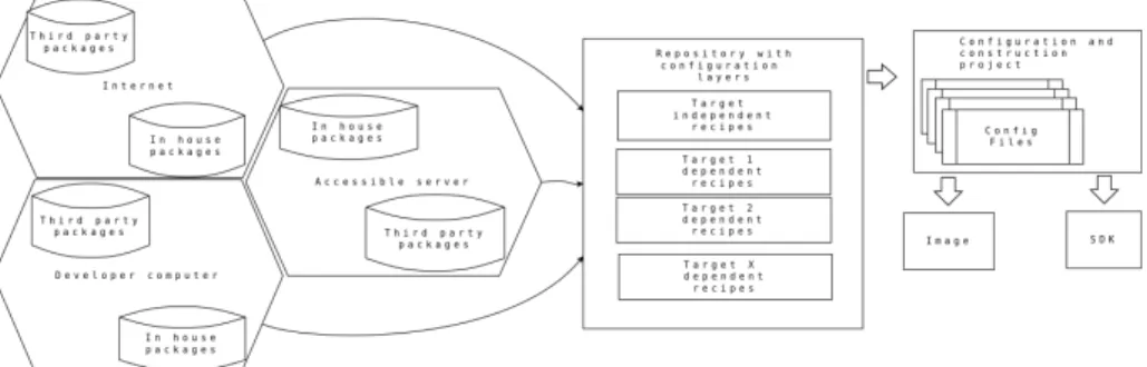
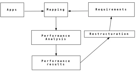
One of the main objectives on this research is to study how the proposed con-struction system using Yocto as its build system, can be used for the software development of small satellites. In addition, the development of software for different processors and co-processors is study, incorporating the required de-velopment tools into the construction systems. On figure 1.2, the proposed construction system is shown.
Figure 1.2: Proposed solution for software development on small satellites
of software. The platform dependent layers contains the specific packages imple-mented for the small satellite vehicle. It also is capable to perform patches and fine-tuning packages in the layer independent layer, increasing the performance in the specific satellite vehicle.
Yocto project, as the internal build system for the embedded software of a satellite, and the implementation of its layer subsystem, can overcome the problems presented before, and still give support on some of the important development process used until today. For example, Yocto allows the creation and packing of an SDK, which can be use by development teams using off-of-the-shell solution. This will reduce the compatibility risks on the creation of the different pieces of software with the main operating system of the small satellite main computer.
It is also possible to open the door on new ways for innovation without risking the project. It allows an inexperience user to construct an custom software package for a defined target in a very fast and independent way, leaving the integration problem to the build system.
Finally a configuration and construction project is proposed. The main purpose for this project is the easy configuration, selecting from pre-tested con-figurations the more suited for the selected platform. This configuration fetch the platform specific and platform independent layers and its in the construc-tion process when the packages of software are fetched and constructed. The result output is an specific image or SDK for the selected platform representing the central computer for the small satellite.
Chapter 2
Software development
approaches for small
satellites
According to Carvajal in [6], the design gap in the field of space explorations have two dimensions, hardware and software. In the present chapter different software methodologies used on the development of software for small satellites are reviewed. Understand how the development process as evolve from the early days of space exploration will help to comprehend the arising needs in the field regarding the software development. Once the review of the actual development are completed, proposing development methodology is possible, one which not only capable to sustain the actual development, but capable to create opportunities to improve and innovate.
2.1
Software methodologies used for satellites
design
The development methodology in a project can determine its success or failure. It is the one in charge of trace the design, limit the scope of what needs to be done and administrate the available resources in the best possible manner [23]. The space exploration projects do not escape from this, specially the design of small satellites, which by its size requirements and mission scope, have limited resources, and limited development time.
Because of the high requirements on quality for the satellites design, very little room exist for innovation. This causes to use space proven, though often outdated technologies [9]. Also a lot of money and effort is placed on the devel-opment of those systems, but with the limitation exposed, the develdevel-opment of satellites has historically been limited to first world countries with large budgets. The high integrity of a project is reflected on the standards used. These
regulates the software development due to the high importance of the projects and the components involved on it [31]. The satellite development lacks of a well defined standard. There exist several initiatives for standards, however they are still in the process of acceptance. One example is the presented by the European Cooperation for Space Standardization (ECSS), an institution that release several standard documents for space engineering, like the one shown in [34]. I seek for harmonization of software methodologies for satellites designs. It centers in modularization of pieces of software in order to increase the re-utilization. With the modularization, the quality and stability of the code is increased, been able to corner the pieces of software that may present problems. Several researches has been done on different methodologies for the design of small satellites, all of those having in common the search for a simple and intel-ligent way to expose the design and share the knowledge between a development team. Known methods used on other fields has been implemented, for example the use of UML (Unified Modeling Language) diagrams to set the requirements into a design model. The UML language, take advantage of the graphical facil-ity to communicate the design model in order to understand the requirements. Other graphical tool used for the satellite software design is the Matlab tool Simulink [15]. It uses the blocks to describe the movement of information and processing data, giving quick simulation results and allowing the validation of the design.
A very common methodology used on the design of small satellites is the model driven design [33]. It is an approach that structures the specifications and guidelines in different models for its study. In addition, different approaches like the one in [26] are commonly developed. In this approach [26], a new paradigm is introduced by the use of OPEN-SBM modeling (a methodology using graphical interface), using the System Requirements Design (SRD) to generate the development environment.
The University of Southern California made several studies on the optimiza-tion of the tool SPIDR, which uses a graphical interface to model the system and test the validity of the model, however the most important part of the project was to transform those models into software in a automated way, something that was not achieved [15]. The use of formal languages for the description of the desire implementation was also approached [11]. This approach was hard to follow by the development teams because of the high level of knowledge required, resulting hard to include new personal
2.2
Small satellite design and structure
In order to design software for a satellite is important to get to know the hard-ware for what it is designed. The small size satellites, often called pico-sats, nano-sats or micro-sats, are generally less than 200kg. Its size goes from a refrigerators to small soda cans [9]. Those small satellites give potential bene-fits over traditional space satellites, for example, the fast development and the project cost.
Small satellites provide amazing alternatives to the developer community. They are driven by ”smaller, faster, better, cheaper, smarter” mentality which allows these satellites to be build with a fraction of time and cost of traditional satellites [9].
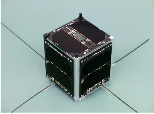
A design who gaining a lot of acceptance in the developer community is the Cubesat design. A simple Cubesat is a small satellite, a 10cm cube with the requirement to be less than 1kg of mass [19]. The dimension of the Cubesat are one of the only hard restrictions of the design, which needs at least two dimension of 1U, 1U being 10cm, while the third dimension can be a multiple of 1U, for example 2U of 3U [8]. Nowadays the Cubesat design is the most pop-ular because of its development low cost and structural simplicity. A example Cubesat is shown in figure 2.1.
Small satellites have, as the brain of the mission, an On Board Computer (OBC). The OBC is the one in charge of the main operation of the system, including the control of several subsystems. As mention in [3], the software system of the satellite may be divided in several subsystems.
• Platform monitoring: Is the subsystem in charge of review the state of the satellite by periodically reading important data and comparing it against expected performance values.
• Telemetry and telecommand: Satellites are not completely autonomous systems, they need to communicate the information collected to other station, or receive orders to perform their mission. This subsystem is in charge to interact with the telecommunication hardware in order to send or receive messages.
• Attitude determination and control system: This subsystem is in charge of the orientation of the satellite with respect to the Earth, and if needed, takes corrective actions in order to keep within specific values.
Usually all these tasks are handled and controlled by fully separate systems, but the one in charge of the control and interaction of data is the central pro-cessing unit OBC. A good integration in a platform with higher capabilities, may escalate into better performance and more flexibility. In addition the need for modular software components are shown. This modules will directly map the different subsystems of the satellite, maintaining coherency.
2.3
Central computation system in satellites.
Ho-mogeneous and Heterogeneous systems
An homogeneous architecture is one with only symmetrical processing units. It has been the simplest approach for small satellites approach, in some cases, the used of only one processing unit is prefer by the developers because of its simplicity. In counter part, the heterogeneous architecture, its a new approach gaining strength in satellites projects because of its versatility. It involve differ-ent processing units, each one specialized for a defined task, sharing information sharing information between each others. The development on heterogeneous systems is more complicate, which provoke rejection on the developers without experience, regardless of the possible advantages it may bring. Great debates have been around the use of different architectures in the space exploration projects, but all have one point in common, which relate the correct selection of the architecture to use with the study of the requirements for the final system.
1FUNcube-1 CubeSat Satellite in the ISIS clean room in Delft prior to being launched.
An incorrect selection of the architecture may involve the failure of the whole project.
Homogeneous systems are simple, all the processing is performed by one kind of processing unit. The behavior and the management of data is the same, which make the things easier for the developers. The memory coherency is an exam-ple of simplicity on homogeneous systems, which has been taken for granted in homogeneous multiprocessor and multi-core systems for decades. Instead, allowing heterogeneous processors with CPU, GPU, DSP, FPGA to maintain coherency in a shared memory environment is a revolutionary concept. In ad-dition to heterogeneous systems complexity in software is the communication between the various processing units[5]. It reveal to be not only a challenge for the software developers but also for the system designers. They need to have in mind not only how to unlock the computational performance in parallel systems by keeping a high integration of the blocks, but also to provide the system with the means of giving the separate blocks a way to access shared memory and data to communicate between each other. As mention before, the communica-tion between different units is a very important and delicate task. As stated in [22], is important to know the path between the sender and the receiver of data, in order to determine if the bandwidth for a communication matches the requirements for an application. If not, it should be redesigned. The energy requirements of the system are very important, and become specially relevant when discussing space exploration projects. Satellites energy subsystems must provide with energy for a large amount of time and with reduce waste. An evaluation algorithm can be implemented in order to optimize the energy con-sumption of the system [22]. This algorithm will allow to determine if the use of a heterogeneous over a homogeneous system justify the developing effort, however this is left to future research.
space project research, which improves the performance significantly compared to the lower end microcontrollers, but the complexity of the system and the code running on it is increased.
The increase of the complexity in the design for a heterogeneous system is a reality, but its important to have into account conclusions given by [5]. Its necessary to break the old way of thinking were all high integrated systems will be useless against radiation. Its proven that a good design make tolerate the average radiation in space exploration missions. The performance between architectures is also compared by [5], were state-of-the-art processors for space usually performs at 900 MFLOP, while the one developed and tested using a het-erogeneous architecture performs at least 1510 MFLOP at a comparable power consumption. The significant speed improvement using the co-processors on a heterogeneous system is important. It lead to the investigation and implemen-tation of better algorithms to obtain better results. For example in [5] the use of the GPU for accelerated image analysis using OpenCL, enables the hardware to reach up to 1000 PAL resolution frames per seconds for certain functions, which certainly could not be accomplished using simple homogeneous system with general purpose processing units. It reveals the need of the space explo-ration development to move to development procedures which allow to take advantage of new architectures with better capacities. In addition, because of the complexity to develop for more robust architecture, it is necessary to have a way to check for the develop code and its integration with the systems, a task which could be automate by the use of continuous integration systems.
2.4
Different approach on software development
for small satellites
In the review of different methodologies of software design for small satellites, two software development approaches are clearly defined. The most common and used method until now is the monolithic design. With this approach, the software is develop as one entity, having clear interaction and dependency be-tween the different algorithms implemented. The second development approach is the design by component. This approach define different components of soft-ware into a basic modules, where each algorithm can be develop in separate. Each development process is reviewed in order to understand its benefits.
2.4.1
Software development: Monolithic approach
Figure 2.2: Monolithic development2
The monolithic software development, as shown in figure 2.2 has its ad-vantages. Each software part of the system is designed and optimize to work taking the best capacity possible from the available resources. The designed and implemented code is highly optimize for the developed platform and strongly coupled with the other algorithms for the satellites. The code develop with this approach lacks portability. In case another space exploration is required using another platform for the satellite, it is required to redesign and re-implement the software solution. This approach use to be the best for small systems which only perform a little number of task, as each task must be highly couple with the others. Nowadays small satellites complexity grows in hardware, and software, which leads in problems implementing this development approach.
2.4.2
Software development: Development by component
The space exploration gained strength in the last years, specially with the pro-liferation of small satellites projects, because of this, the need for better designs arises. Different developers groups are investigating new methodologies and de-sign paradigms. Something they all have in common is the need of modular reusable designs in order to reduce cost and development time. The main idea
is to separate the problem in different modules and use different pieces of soft-ware and algorithms in order to solve specific problems. This idea is widely spread in the satellite developers community. One solution is the use of off-of-the-shell components[9]. Those components are usually bought from third parties companies or created by specialized research teams inside the project. The components are later integrated in the project.
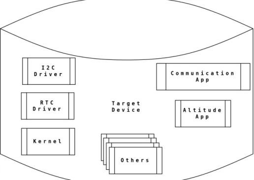
Figure 2.3: Development by component3
The use of components allow developers to treat the problems for a mis-sion in a modular way, as shown in figure 2.3. It leaves the big work load of the algorithm implementation to a specialized team. The developer team in charge of each module use to have deeper understanding on the requirements of the component and how to implement it in a proper way. Development by component approach is rapidly gaining strength in the satellite development community, but also arise the need of high quality pieces of software, with high compatibility, optimize for its sustainability and performance. Development us-ing this approach need for a integration phase, where compatibility between the different components are tested and modified in order to construct an image containing all the software packages.
Yocto as a solution follow this approach. It is a build system that take care system integration. It allows the developer to focus in the component develop-ment and rapidly test for the integration of a module with the complete system. Yocto can include third parties designers only capable of provide the source code or the binary representation of the component because Yocto build system is capable of produce an SDK. This SDK has the basic required packages and development tools to compile an application. By this way, the developers com-pile their software modules with the same toolchain and tools used to generate the main OS. It reduces compatibility on the integration phase.
2.5
Open Source tools on the design and
imple-mentation of software satellite
The use of Open Source tools on space exploration projects are usually rejected by the instability of packages between versions and releases. It is common to think that the required stability will only be found from commercial software, however, this is not true. There are several Open Source software with very stable lines of development. This project have big developer communities be-hind, which give support and provide a good quality to the product. One good example is the Yocto Project, a build system which come to bring stable releases and serves to build stable constructions systems [24].
Chapter 3
Integration of build system
for small satellite missions
A build system is a suite of programming tools arrange to perform a construction task without the intervention of the user. This process can be as simple as generating the structure for a project, to the hard task of creating a complex operative systems and specific pieces of software. The selection of the correct build system to use depends on the requirements of your project and how can be adjusted to it. In addition, how well supported the project is and how the developer can adapt to work under it must be take into consideration. In this chapter we focus on the study of different build systems available on the Open Source community, and determine which one is the best fit for the proposed solution on software development for small satellites.
Several types of build systems are available today, each one trying to solve a specific necessity. The problem they are designed to solve determine the way it works and how it is implemented. The study build systems are Buildroot, PtxDist, LTIB, OpenWRT, OpenEmbedded,, Geento. There are many more build systems available in the Open Source community, however, the selected are the more robust and with the biggest support by active communities. This avoid to use a solution that will be deprecated in a few mounts.
3.1
Build systems as an improvement on the
de-sign methodology
The design of a embedded system is not an easy task specially for small satellites. There are several groups of design and development for software and hardware. They are working together on the creation of a functional system which solve in the best way the specified requirements. Several design approaches can be choose in the development of a small satellite. It may go from the aspect of using available hardware or one that can be created, to which software is available
or can be implemented, basically hardware versus software approach. How to connect both aspect in a final product will define how effective the development process is. As more complex design and implementation is required, the final cost and development time for the release of a system is increase. This time can be the inflection point on the decision to launch or not a project. Because of this is important to find an approach that could coexist and improve the hardware and software development.
This research focus on the software for the small satellite, however the pos-sible development solutions proposed doesn’t have to ignore the fact that the platform running the software may not be already available. This is the real-ity several projects today, where the hardware of the system is under design, development, or studies to be acquired when the software begging its design and development. Because of this, a flexible approach of development should be selected. It should be able to show results on early stages of development and can be quickly ported to new platforms. On the cases where changes on the platform are perform, build systems are a great decision for a project, but it must be in companion of a good development methodology. For example, if the Y chart methodology is implemented, the software development can advance on the system level and detect malfunctions or lack of accomplishment on the requirements. The use of a build system will bring the flexibility to rearrange the software to still be functional on the next iteration of development where changes on the platform can be implemented.
As stated in [20], the Y chart it is a methodology to provide designers with quantitative data by analyzing the performance of architectures by a given set of different application. It gives the designers a concrete idea of how the final product behave, but the important part of the methodology is the flexibility on going back to stages where deep infrastructural changes can be made. As stated in [10], the methodology makes the assumption that each design can be modeled in three basic ways, which emphasize different properties, those properties are design behavior (function, specification), design structure (netlist , block diagram), and physical design (layouts, boards, packages).
Figure 3.1: The Y chart approach with the different development stages1
The use of a build system can improve the development on a project, how-ever, What is the best build system to use?. The response to this question depends on the specific requirements of the project, because a solution which work for the development of automotive projects will not be the suited on the design of software for space exploration. There are a number of build systems available which solve different necessities and they are better suited for differ-ent applications. Next we cite the differdiffer-ent build system that were taken into consideration.
• Buildroot: It is a very easy to use build system to generate Linux sys-tems, base on a set of Makefiles and patches, which are in charge of the generation. It can generate the toolchain, a root filesystem, kernel and bootloader images. It is very popular and mainly used between people working with small embedded systems which required customization [21]. Buildroot is better suited for kernel developer more than application devel-opers, although they are not excluded as Buildroot has a simple structure to understand.
• PtxDist: It is a build system designed for the creation of your own Linux distribution, as they state, it is not a distribution, but what they call ”a executable documentation”, comprising all the steps necessary to create a customize complex distribution for the target system, been in majority easy to use for a inexperience user.[36]. PtxDist is a easy build system, however several steps on its configuration are better if they are performed by experience users. Once configured, the creation of build systems are straight forward. This build system has really good documentation about Linux porting, drivers incorporation and bootloader porting.
• LTIB: It stand for Linux Target Image Builder and is a tool that can be used to develop and deploy board support packages (BSP). It supports different architectures like ARM and PowerPC [16]. LTIB has a very gran-ular configuration and incorporate over two hundred packages, however for the non experience user its configuration can be tricky and exhausting.
• OpenWRT: It is know as a Linux base distribution, which instead of pro-viding a static single firmware, provides a fully writable filesystem with package management, freeing the user from the target application config-uration [25]. Its easy to use but it stay as only a Linux base distribution.
• OpenEmbedded: It is a build framework for embedded Linux. It offers a best-in-class cross-compile environment. It allows developers to create a complete Linux Distribution for embedded systems supporting many architectures, multiple releases peer architecture, easy configuration, tools to increase the speed of construction and with a lot of supported packages which can be integrated in the final image [28]. It is the base for other build system like Yocto, on which this document discusses in further sections, however, because is so big, its structure is a little messy and developers can be easy mislead on the quantity of files and configuration knobs.
• Yocto: The Yocto Project is an open-source collaboration project focused on embedded Linux developers. Among other things, the Yocto Project uses a build system based on the OpenEmbedded (OE) project, which uses the BitBake tool, to construct complete Linux based images. The BitBake and OE components are combined together to form Poky, a ref-erence build system [32].You can use components from the Yocto Project to design, develop, build, debug, simulate, and test the different packages for different platforms.
• Geento: It is a free operating system based on either Linux or FreeBSD that can be automatically optimized and customized for just about any application or need. Extreme configurability, performance and a top-notch user and developer community are all hallmarks of the Gentoo experience [12]. However as OpenWRT it is only a System distribution.
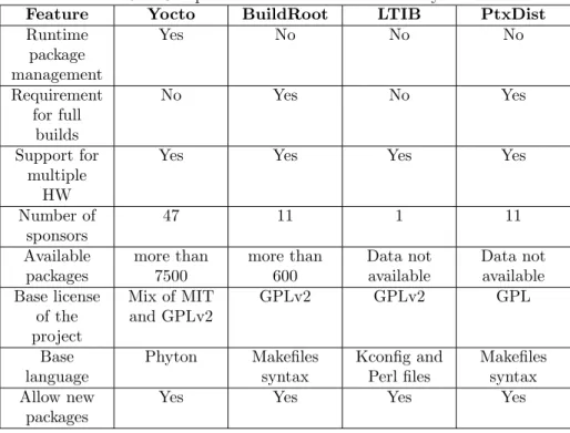
The construction system proposed on this research will use a build system as the central point of configuration and construction. This build system must accomplish several requirements beside fit the solution proposed. It also must support modularity of the solution, been stable and well documented and have a good community support between other characteristics. On the next table is shown a review of the different features of the mention build systems. The build systems focus as only base distribution are not taken into account as its design as only distribution systems do not fit into the proposed modular solution.
2Comparison between different build systems. Information taken from [12], [32], [28], [25],
Table 3.1: Comparison between different build systems2
Each build system counts with their special characteristics which make them unique. Is up to the developer to choose a build system which fit the best for its application. In the case of software development for space exploration, and specially for the proposed solution, the modular capability is very important. Having runtime package management allow to apply modification to the config-uration and construction of a package in a dynamic and modular way, having the build system resolve the order of modification by priorities set beforehand. It is very important the support the build system has from the community, because it assure a longest live, more documentation available and more devel-opers capable of bringing help around the world. In addition, the development for small satellites has not grow enough on the software side, relaying on tools or third parties for the software development. Because of this seeking for a easy to learn language for the development of the build system is necessary. Yocto base its recipes of Python language, it is not the best language around, but it is very easy to learn and understand in a high level.
• Allow OS customization.
• Allow package customization and version selection.
• Minimal or none impact on packages customization.
• Reduce developers effort on software modification.
• Good support for the Open Source community.
• Count with stable and proven releases.
• Flexibility on platform changes, intending to reduce packages changes.
3.1.1
Yocto build system
The Yocto Project is an open-source collaboration project focused on embedded Linux developers. Among other things, the Yocto Project uses a build system based on the OpenEmbedded (OE) project, which uses the BitBake tool, to construct complete Linux based images. The BitBake and OE components are combined together to form Poky, a reference build system [32]. You can use components from the Yocto Project to design, develop, build, debug, simulate, and test the different packages for different platforms. Yocto is not just aim to develop an OS distribution, or a piece of software, Yocto is more complete than that. It allows the developer, by the use of different recipes, to describe pro-cess of construction for any kind of project. The different projects to construct with Yocto goes from the construction of a toolchain or the construction of the OS for a specific board, to the compiling process of a simple hello world ap-plication. On figure 3.2 is illustrated the development environment using Yocto.
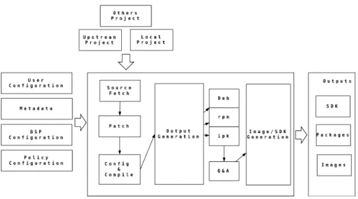
For the development process presented on this research, the Yocto project is used as the core build system of a construction system capable to construct the operative system of the small satellite. It is also capable of construct and deploy an SDK with the available packages and the tools by which the software of the small satellite is generated. The packages of software that will be run on this OS can be also be constructed by itself, giving the choice to construct only the required package. The selection of the final output is selected by the user of the build systems. This process is exemplify in the figure 3.3.
Using a build system like Yocto for the design and implementation of small satellites will be an improvement on the development methodology used until now. It increase the availability of resources and its maintenance, taking advan-tage of a big community behind it. The use of the build system will impact on the development time, the cost, the scalability and the stability of the project. The modularity given by this tools will also help to improve the development process, allowing more specialized groups to include and work on different pieces of software without disrupting the integrity of the whole project.
Figure 3.2: Yocto Project Development Environment3
Figure 3.3: Building an Image with Yocto4
Yocto Layers
The Yocto project allows the creation of different layers to organize the different Metadata and recipes that will be use in a project. This layers allow to encapsu-late all the necessary packages and configuration necessary. The main purpose of layers is to isolate different types of customization from each others[32]. This layer methodology allow developers to keep things in a modular way, encapsu-lating images with certain packages, and deploying the correct output(an image or a package) for the selected target.
Chapter 4
Development platforms
The flexibility in the support for different platforms is one of the advantages of the current implementation. It allow the support for different development boards with different capacities and different cores. It even allow to include new targets in the future. For example, platforms with single or multiple processing units in symmetric or asymmetric architecture can be added to the construc-tion system. Supporting different targets may help in the fast development for different missions with different requirements. In addition, having support for different target can be used to compare performance and determine which one is better suited for an specific mission. The small satellite development lower the cost of the its target vehicles, however the are not available to all develop-ers groups, having prices around $4000 USD to even $15000 USD. Because of the high prices, researching about new available vehicles which meet the desire requirements for a space mission becomes really important. Even the research on target vehicles with similar characteristic on the final available target can enable developers to start the software development. The target development boards for this project are developed by Texas Instruments, they are Open Hardware projects which allow the user to have knowledge and some specific insights on the used architecture and BSP. Some of these vehicles were used for space projects or are in the scope for possible future missions.
4.1
Beagleboard XM
The Beagleboard XM is a low cost ARM Cortex A8 board which has compat-ibility with several Cortex A8 processors manufactured by Texas Instrument. Which processor is used depends on the revision and the capabilities desired for the board. There are version of the board with a DM3730 and AM3715 pro-cessors. The main difference is the DSP, which is not included in the AM3715 version. The version used on this project is the one with the DM3730 processor. The Beagleboard XM was born from the original Beagleboard project, which was a development board with a Omap3530 SoC. The newest version, the
gleboard XM, is a more powerful board, with higher operation frequency of its processor and its DSP, with new features like a uSD, camera header and over-voltage protection.
Figure 4.1: Beagleboard XM1
The Beagleboard XM shown in figure 4.1 is a development board aimed to the Open Source community, equipped with the many features to experience the processor capabilities but not intended as a full development platform, instead is a first step for a more complete design. This board used standard interfaces making it highly extensible to add more features. All of the design information is freely available and can be used as the basis for a product [35].
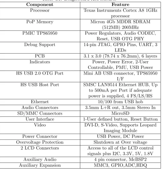
Many of the Beagleboard XM features are shown in the next table.
The Beagleboard XM used on this project is the one with the DM3730CBP 1GHz processor which comes in PoP package, a technique where the processor is mounted on top of the processor. This is a important piece of information, although the benefits of a PoP package at electrical level, also because when you look into the board, you will not see the number part of the processor, instead you will see the part number of the memory.
The Beagleboard XM has been use in space exploration missions before. One example is the USS Langley mission, on which the Beagleboard was include on
Table 4.1: Beagleboard XM features2
Component Feature
Processor Texas Instruments Cortex A8 1GHz processor
PoP Memory Micron 4Gb MDDR SDRAM (512MB) 200MHz
PMIC TPS65950 Power Regulators, Audio CODEC, Reset, USB OTG PHY Debug Support 14-pin JTAG, GPIO Pins, UART, 3
LEDs
PCB 3.1 x 3.0 (78.74 x 76.2mm), 6 layers Indicators Power, Power Error, 2-User
Controllable, PMU, USB Power HS USB 2.0 OTG Port Mini AB USB connector, TPS65950
I/F
HS USB Host Port SMSC LAN9514 Ethernet HUB, Up to 500mA per Port if adequate power is supplied, 4 FS/LS/HS Ethernet 10/100 from USB hob Audio Connectors 3.5mm L+R out, 3.5mm Stereo In SD/MMC Connectors MicroSD
User Interface 1-User defined button, Reset Button Video DVI-D, S-Video, Supports Leopard
Imaging Module Power Connector USB Power, DC Power Overvoltage Protection Shutdown at Over voltage
2 LCD Connectors Access to all of the LCD control signals plus I2C, 3.3V, 5V, 1.8V Auxiliary Audio 4 pin connector, McBSP2 Auxiliary Expansion MMC3, GPIO,ADC,HDQ
4.2
Pandaboard
The Pandaboard is a development board designed by Texas Instrument. The SoC of the Pandaboard may vary between the Omap4430 or the Omap4460 (it depends on the board revision), been the latest the one known as the re-vision ES of the Pandaboard. It has a dual core ARM cortex A9, giving a Symmetric Multiprocessing (SMP) capability. It counts with a graphics core, a POWERVR SGX540, capable of supporting actual graphics API’s as OpenGL or OpenVG. The SoC of the Pandaboard contain a DSP subsystem, base on TMS320DMC64x very long instruction word DSP Core. Also a IVA-HD sub-system image and video acceleration. The Pandaboard also counts with a ARM Cortex M3 processors. The M3 may be programmed for specialized purposes and communication between the different subsystems. The Pandaboard have peripherals to interact with the processing system as USB ports to connect key-boards, mouse, camera, and other USB devices, HDMI ports, a 3.5 jack for input and output audio allowing stereo input support, SD connector card, 10/100Mb capable Ethernet connection, wireless connection by WiLink, supporting 802.11 b/g/n and bluetooth, and many other peripherals[30]. The Pandaboard ES used on this research is shown in figure 4.2.
Figure 4.2: Pandaboard development board3
The available Pandaboard in which the generated OS is tested is the ES revision. This revision contains an Omap4460 SoC, however the build system is intended to support the Omap4430 version. For the rest of this document we refer to the Pandaboard ES. The next table, taken from the system reference manual of the board [29], list the different features of the board.
Table 4.2: Pandaboard ES features4
Component Feature
Debug Support 14-pin JTAG, GPIO Pins, UART via DB-9 connector, LEDs PCB 4.5 x 4.0 (114.3 x 101.6 mm), 8
layers
Indicators 3 LEDs (two user-controlled, one overvoltage indicator) HS USB 2.0 OTG Port Mini-AB USB connector, sourced
from OMAP USB Transceiver HS USB Host Port Four USB HS Ports, up to 500mA
current out on each, two onboard connectors, two expansion
connectors
Audio Connectors 3.5mm, L+R out, 3.5mm, Stereo In SD/MMC Connectors 6 in 1 SD/MMC/SDIO, 4/8 bit
support, Dual voltage User Interface 1-User defined button, Reset
Button, SYSBOOT3 switch Video DVI-D or HDMI, Optional user
provided plug-in display Power Connector USB Power, DC Power
The Pandaboard ES, using an OMAP SoC present the same problems as the Beagleboard regarding instability when powered by batteries or alternate power supplies which may present variations. However, the Pandaboard present a powerful core processor, the Arm Cortex A9, very common in the development of advance embedded systems and with great capabilities for the development of space exploration missions. It also present different subsystems, which extend the possibilities for developers to develop and test software which communicate between each other. On figure 4.3 is shown the architectural block diagram of the Pandaboard ES and its subsystems.
4Pandaboard features taken from [29]
Figure 4.3: Pandaboard general block diagram5
As shown in figure 4.3, the OMAP4460 is composed of the following subsys-tems.
1. Cortex-A9 microprocessor unit (MPU) subsystem, including two ARM Cortex-A9 cores capable of operation at 1.2GHz.
2. Digital signal processor (DSP) subsystem.
3. Image and video accelerator high-definition (IVA-HD) subsystem.
4. Cortex-M3 MPU subsystem, including two ARM Cortex-M3 microproces-sors.
5. Display subsystem.
6. Audio back-end (ABE) subsystem.
7. Imaging subsystem (ISS), consisting of image signal processor (ISP) and still image co-processor (SIMCOP) block.
8. 2D/3D graphic accelerator (SGX) subsystem.
9. Emulation (EMU) subsystem.
The Pandaboard ES is a great development board with a lot of capabilities. It counts with the support of Open Source community which move with the latest news available, making it easy to use, specially for the central processing. The available diversity in different subsystems make available to developers to design, develop and test pieces of software which can be ported later if necessary.
4.3
Beaglebone
The Beaglebone development board is a platform developed by Texas Instru-ment, with the main purpose to create a easy to use target to experimented developers and the new developers joining to the embedded world. There are two flavors of the Beaglebone. The white version, a development board around the $89 USD, with a DSP, integrated DFI chip and on chip JTAG for debugging purposes. The black version is the latest edition, designed to address the Open Source Community, early adopters, and anyone interested in a low cost ARM Cortex-A8 based processors because its price its around the $45 USD [2]. The construction system has support for both version of the Beaglebone, as its main differences are addressed by they device tree files, however the related testing shown in this research its developed on the Beaglebone Black (BBB).
The BBB has been equipped with minimum set of features to experiment with, however its not designed to be a full development platform, neither to be the main computer for a satellite, as some features of the processor are not accessible from the BBB interfaces. Both version allow the use of add-ons boards called capes, to add many different combinations or features to the ones already provided [7]. On figure 4.4 is shown the Beaglebone Black used for the research. Both version of the Beaglebone are design to be compatible between each other as much as possible, but there are several areas of differences between both of them. The more important difference is in the processor, which continue being part of the AM3xx family, but present an increase in its speed (1GHz). In addition, there’s no JTAG emulation over USB on the BBB as no serial port by default is present. The BBB add an on-board managed NAND (eMMC) of 2GB and 512MB DDR3L, which is a increase of size and a performance boost with cost reduction. Next are shown some of the BBB features [7].
The Beaglebone Black has been widely accepted on the Open Source Com-munity, opening the embedded world to a lot of new developers. On this project, the BBB support is added to show the scalability and the capability of multiple platform support of the build system. Its beyond of this research a radiation analysis and other requirements to validate the board as a satellite vehicle. In-stead, we focus in its capability of supporting the software of the satellite and the advantages it may add to the project. In addition, its support allows the developers to use a simple board, easy to acquire, with good support and easy to program, increasing its experience with embedded systems. Furthermore, the
Figure 4.4: Beaglebone Black6
Table 4.3: Beaglebone Black features7
Component Feature
Processor Sitara AM3359AZCZ100 1GHz, 2000 MIPS
Graphics Engine SGX530 3D, 20M Polygons/S SDRAM Memory 512MB DDR3L 800MHZ
Onboard Flash 2GB, 8bit Embedded MMC PMIC TPS65217C PMIC regulator and
one additional LDO Debug Support Optional Onboard 20-pin CTI
JTAG, Serial Header Power Source miniUSB USB or DC Jack, 5VDC
External Via Expansion Header PCB 3.4 x 2.1, 6 layers Indicators 1-Power, 2-Ethernet, 4-User
Controllable LEDs HS USB 2.0 Client Port Access to USB0, Client mode via
miniUSB
HS USB 2.0 Host Port Access to USB1, Type A Socket, 500mA LS/FS/HS
Serial Port UART0 access via 6 pin 3.3V TTL Header. Header is populated Ethernet 10/100, RJ45 SD/MMC Connector microSD , 3.3V
User Input Reset Button, Boot Button, Power Button
Chapter 5
Design and implementation
of the construction system
On the present chapter, the design and development of the construction system is reviewed. The construction system is constructed in a modular way to fulfill the requirements of scalability and reusable pieces of software. The construction system follow the design pattern described in figure 1.2. It is intended to take pieces of software for different sources and integrate it into one construction system in order to generate a functional image.
The construction systems uses Yocto project as its internal build system, abstracting the set up process from the user. It encapsulate the basic packages needed and the for a target board, which allow the easy selection and configu-ration of a custom Linux OS distribution, ready for the deploy and testing on the selected target.
5.1
Construction System
The construction system is the principal abstraction layer of the proposed so-lution. It is a simple but powerful encapsulation made around the principal components of the proposed solution. The basic idea of this encapsulation is to be able to overcome the difficulties of change or modification of internal com-ponents, including the build system. This abstraction layer allow developers to focus on specific tasks without worrying about integration, leaving this task to developers specialized in the construction systems itself.
The construction system structures is shown on figure??. The construction directory structure is designed to be as simple as possible in order to avoid proliferation of files, on which developers may get lost. The Makefile.inc file contains definitions of variables necessary for the construction of the project. It includes the URL’s of the different repositories, the configuration files needed and the required structure of the project once is configured. The different configuration files are located at tools/config files. Each pair of bblayers.conf
and local.conf files exist by available hardware target and are in charge of the full configuration of the system. On tools/scripts there is the principal script of the construction system, build script.sh. This script source the environment of the core build system, in this case Yocto build system. It also take care of triggering the construction of the system.
Figure 5.1: Directories of the construction system1
All the process is controlled by the Makefile. It is the one in charge of provide the different targets available to the user as config, build, clean, distclean and help. It is the one in charge to interact with the user of the build system. It is designed to be as simple as possible to the user, which is in charge of provide a few simple targets in order to construct an image for a target. In order for the construction of an image the only necessary targets are config and build targets. The config target will fetch all the layers necessary, dependent and independent from the hardware. The build target will trigger the build system for the construction of the image.
5.1.1
The hardware independent layer: meta-tecSat
The meta-tecSat layer is a custom Yocto layer created to keep all the hardware independent configurations and packages for the system. It allows the user add this layer and it dynamically select the wanted packages to create a simple and functional image, including the configuration for the custom distribution. The created images are base on Linux. Currently the layer support three different
image types, tecSat-image-minimal, tecSat-image and tecSat-image-dbg. It also declare an environment standard variable indicating the inclusion of packages from a hardware dependent layer. The tecSat-image-minimal is a minimal cus-tomize image base on Linux, which allow a functional system to boot up with the minimal support of a Linux system. The tecSat-image is base on the minimal image, but it add the more packages defined by the user which will represent the specialized software for the satellite. When developers add independent pieces of code for specialized functions in space exploration, they will be added to this image. The third image available is a debug image, base on the tecSat-image. It adds debug packages with capabilities to support eclipse debug and packages to review performance. For example, this images add packages capable to do tracing at user or kernel level.
Inclusion of the meta-tecSat layer allow the customization of the distribu-tion. By specifying in the local.conf file the distribution type wanted, it may be a tecSat distribution or a normal poky distribution. The tecSat distribu-tion contains special configuradistribu-tion which avoid not needed packages in order to reduce footprint of the whole image. By itself, the meta-tecSat layer is not capable of the entire construction of the system. It is require to associate this layer with a platform dependent layer in order to assure the correct construction of the image. Otherwise the target platform for which the construction is made may not be available or may contain undesired features.
The different layer implemented has its own priority. The meta-tecSat layer has lower priority than the hardware dependent layers. The reason for this design constrain is to allow platform specific modification, which should be append to the original recipes in the meta-tecSat layer by the recipe appends methodology. Those appends could include patches and new pieces of software in order to increase the performance of the package but only if necessary.
5.1.2
The hardware dependent later: meta-tecSat-target
The hardware dependent layers are the custom Yocto layers created in order to keep all configuration and special packages which depends strongly of the target platform they are executed. Example of this packages are the kernel and the bootloader. The hardware dependent layers are interchangeable between each others, been only one needed and used at the time. Which layer is used depends on the selected target and specified in the local.conf file of the Yocto build system. If other layers besides the one referring the target exist, they are simply ignore.
The convention for the name of the layer follow the pattern meta-tecSat-target, where target must be replaced with the name of our target platform. For example, if our target platform will be a Beagleboard, the name of our hardware dependent layer will be meta-tecSat-beagleboard. This approach allow developers to create new layers in the future for new platforms.