1
Random and oriented electrospun fibers based on a multicomponent, in
situ clickable elastin-like recombinamer system for dermal tissue
engineering
Israel González de Torre
1, Arturo Ibáñez-Fonseca
1, Luis Quintanilla
1, Matilde Alonso
1,
José-Carlos Rodríguez-Cabello
11
BIOFORGE, CIBER-BBN, Edificio Lucia, Universidad de Valladolid, Paseo Belén 19, 47011,
Valladolid, Spain.
Dr. Israel Gonzalez de Torre
G.I.R BIOFORGE, Universidad de Valladolid
Paseo de Belen 19
47011, Valladolid, Spain
E-mail:
[email protected]
Dr. Arturo Ibáñez-Fonseca
G.I.R BIOFORGE, Universidad de Valladolid
Paseo de Belen 19
47011, Valladolid, Spain
E-mail:
[email protected]
Prof. Luis Quintanilla
G.I.R BIOFORGE, Universidad de Valladolid
Paseo de Belen 19
47011, Valladolid, Spain
E-mail:
[email protected]
Prof. Matilde Alonso
G.I.R BIOFORGE, Universidad de Valladolid
Paseo de Belen 19
47011, Valladolid, Spain
E-mail:
[email protected]
Prof. José Carlos Rodríguez Cabello
G.I.R BIOFORGE, Universidad de Valladolid
Paseo de Belén 19
47011, Valladolid, Spain
E-mail:
[email protected]
2
ABSTRACTHerein we present a system to obtain fibers from clickable elastin-like recombinamers (ELRs) that crosslink in situ
during the electrospinning process itself, with no need for any further treatment to stabilize them. These ELR-click
fibers are completely stable under in vitro conditions. A wrinkled fiber morphology is obtained. In addition to a
random fiber orientation, oriented fibers with a high degree of alignment and coherence can also be obtained by
using a rotational electrode. The production of multicomponent fibers means that different functionalities, such as
cell-adhesion domains (RGD peptides), can be incorporated into them. In a subsequent study, two main cell lines
present in the dermis and epidermis, namely keratinocytes and fibroblasts, were cultured on top of the ELR-click
fibers. Adhesion, proliferation, fluorescence, immunostaining and histology studies showed the cytocompatibility of
3
1. INTRODUCTIONNovel biomaterials and biomanufacturing methods aimed at the development of scaffolds for different
tissue-engineering applications have been designed and tested in recent years [1-6]. Indeed, several constructs have been
produced and used for the regeneration of different tissues, such as nerves [7, 8], tendons [9, 10], muscles, bones
[11-14] and skin [15-17]. The latter is the largest organ in the body and the main barrier isolating it from the
surrounding environment, thereby protecting it against external aggressions, including bacterial infections and
chemical or physical damage [18]. The epidermis and dermis, which are outermost layers of the skin, are mainly
composed of keratinocytes and fibroblasts, respectively [19], and the presence of elastin is crucial to maintain the
mechanical properties and elasticity of these tissues [20]. The onset of a wound-healing process after trauma or skin
damage leads to a scar tissue that gradually restores the skin barrier over a period of days, weeks or even months,
depending on the severity of the damage [21]. However, the structure of this new skin is not the same as the original.
For instance, this scar tissue lacks the elasticity of the original skin, and the higher collagen production during the
wound-healing process leads to a tissue that is stiffer than its natural counerpart [22]. Hence, it is of great interest to
manufacture elastin-based constructs for use in skin tissue engineering.
The different techniques used to develop scaffolds for this purpose include electrospinning, which involves the
formation of fibers by application of a high voltage to a polymer solution expelled through a syringe to create a
charged liquid jet that flies until it reaches a collector, where the fibers are formed [23-25]. The liquid dries during
this flight, thus allowing the polymer to assemble into a fiber if its properties have been adjusted appropriately.
However, in most cases biopolymer-based fibers need to be cross-linked with chemical reagents in order to avoid
dissolution of the polymer when immersed in water-based solvents or when used in tissue engineering [24, 26, 27].
Furthermore, electrospinning allows the formation of random or axially aligned fibers, for example by incorporating
a mechanically rotating collector into the system [8, 28-30].
Although obtained using a complex and not always feasible set-up, these aligned fibers may find uses in the
regeneration of different tissues that require cell alignment for optimal healing, such as tendon or nerve tissue [4,
31]. However, other tissues, including skin, do not contain aligned structures and the collagen and elastin fibers
present in the extracellular matrix are randomly oriented [32-35]. As such, fiber-based constructs designed for skin
4
With regard to the mechanical properties of electrospun fibers, several materials can be used to optimize theelasticity, with most of these being synthetic polymers whose biocompatibility can be compromised by their nature
[27]. Nevertheless, new recombinant biomaterials with potential applications in tissue engineering have arisen in the
last decades [36], thus facilitating the development of tailored protein-based biopolymers. One of the most exciting
recombinant biomaterials are the so-called elastin-like recombinamers (ELRs) [37], which are formed by repetitive
units of the Val-Pro-Gly-X-Gly (VPGXG)n peptapeptide, in which X (guest residue) can be any amino acid except
L-proline [38]. This pentapeptide exhibits an inherent elasticity as it fold into a β-turn above the so-called transition
temperature (Tt) [39]. One of the main characteristics of the ELRs is their inherent change of structure in water
solution depending on the temperature (transition temperature, Tt), which means that below the Tt the ELR remains
soluble, and above this Tt the ELR excludes water and precipitates [36-39]. Furthermore, the possibility of using
amino acids containing reactive groups in their side chains as guest residues, such as L-lysine, means that they can
be modified to include groups that are even more reactive in order to achieve a “click” chemistry reaction between
ELR molecules [40, 41], thereby simulating the physiological covalent cross-linking of tropoelastin mediated by
lysyl oxidases [42, 43]. Although this approach can also be adapted for the formation of in situ cross-linked
electrospun fibers, to the best of our knowledge there are no reports in the literature in this regard. Hence, in this
work, and for the first time, we provide evidence for the formation of ELR-based fibers that are cross-linked in situ
using an orthogonal “click” reaction between azide and cyclooctyne groups present in two different ELR molecules,
as reported previously [40, 41, 44, 45], without the need for further crosslinking or post-treatment steps.
The recombinant DNA technology used for the biosynthesis of ELRs also allows the inclusion of bioactive peptides
or proteins that may improve the biocompatibility of this type of biomaterials, such as cell adhesion domains
comprising the tri-peptide Arg-Gly-Asp (RGD) [46]. It should be noted that hydrogels formed by the cross-linking
of RGD-containing ELRs following the aforementioned “click” methodology have recently been shown to be cyto-
and biocompatible using several methods [47], thereby anticipating the good biocompatibility of ELR-based
“clickable” electrospun fibers.
In this work stable, electrospun bioactive fibers are obtained by the in situ mixing of two “clickable” ELR
components during the flight of the ELR solutions from the needle of the syringe to the collector. Both random and
5
are able to support cell growth due to the inclusion of RGD motifs. Finally, in vitro biocompatibility is tested usingthe two main cell types found in the outer layers of skin, namely fibroblasts and keratinocytes. Herein, we present
the results from electrospinning optimization, fiber size and orientation, cell adhesion and proliferation, and general
cell behavior (cell growth, migration and alignment) along ELR click fibers.
2. Materials and Methods
2.1. ELRs
The two ELRs used in this work were kindly provided by Technical Proteins NanoBiotechnology S.L. (TP70904,
TP20254, respectively). One of them is a structural polymer with 60% of the amines from the lysine residues
functionalized with cyclooctyne groups (VKVx24-cyclo), whereas the second one comprises integrin-mediated cell
adhesion domains, namely the L-Arginine-Glycine-L-Aspartic acid tripeptide (RGD), functionalized to the same
degree as the former but in this case to include azide groups in the lysines present in the ELR (HRGD6-N3).
The sequences of the ELRs are:
VKVx24: MESLLPVGVPGVG-[VPGKG-(VPGVG)5]23-VPGKG-(VPGVG)3-VPGV
HRGD6: MGSSHHHHHHSSGLVPRGSHMESLLP-[[(VPGIG)2-VPGKG-(VPGIG)2]
2-AVTGRGDSPASS-[(VPGIG)2-VPGKG-(VPGIG)2]2]6-V.
A detailed explanation of the ELRs synthesis and the characterization of multicomponent click hydrogels
implemented with these ELRs have been previously reported [41].
2.2. ELR-click fiber formation
All electrospinning experiments were conducted using a syringe infusion pump (PHD 2000 Harvard apparatus) and
a high voltage DC power supply (Glassman high voltage inc. FC series). HRGD6-N3 and VKVx24-cyclo were
dissolved in 2,2,2-trifluoroethanol (TFE) (Sigma-Aldrich) at a concentration of 50 mg/mL at room temperature.
Recombinamer solutions were placed in 1 mL Hilton syringes (Luer Lock) connected by a specially designed
6
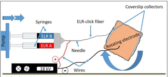
Aligned samples were obtained using a rotary mandrel at a fixed surface speed. This mandrel comprised a copperparallelepiped attached to a shaft, which is inserted into a motor (IKA Eurostar 20 digital). Aligned fibers were
collected on coverslips placed on alternating sides of the copper parallelepiped (Fig. 1).
All the fibers obtained were incubated in water at 277 K for at least 12 hours to assess the covalent crosslinking and
stability of the fibers.
Fig. 1. Schematic set-up of the rotating electrospinning device.
2.3. Scanning electron microscopy
Scanning electron microscopy (SEM) was used to investigate the fiber morphology. Thus, ELR-click fibers were
immersed in cold water (277K) for at least 12 h. Finally, samples were dried at 313 K for 24 h. Images of the
ELR-click fibers were obtained by SEM (JEOL, JSM-820) with no prior coating procedures. Some of the SEM images
were colored using Jasc Paint Shop Pro 9 software (Corel).
2.4. Evaluation of fibers dimensions and orientation
Cell and fiber orientation was evaluated using the OrientationJ plug-in of the FIJI-Image J software, as described by
Puspoki et al. and others [48-50]. Coherency was evaluated for each pixel of an input image by computing the
continuous spatial derivatives and using a cubic spline interpolation [51]. Fiber diameters were determined using the
7
SigmaPlot 12.0 software or Excel 2016 from Microsoft. Randomly chosen regions of nine different samples wereanalyzed.
2.5. Mechanical properties of the scaffolds: micro-tensile test
Tensile strength tests were performed using a precision instrument for small-scale testing (Instron 5944
MicroTester). Ten 30 mm x 5 mm specimens were clamped using anti‐ slip clamps leaving a gap of 10 mm between
the clamps. Tests were performed at 2 mm/s. Load-deformation data were recorded and the stress–strain curve (Fig.
6 SI) of the fibrous structure was obtained from the load-deformation data
.
2.6. Contact angle
In order to measure the hydrophobicity of the sample, contact angle measurements were carried out at 295 K using
the sessile drop method and a Data Physics OCA20 system instrument. The drop profile images during
micro-syringe dispensation of ultra-pure water (mQ) were recorded using an adapted CCD video camera. Contact angles
were measured on both sides of the drop and the average values are reported. The stainless-steel needle tip was
maintained at the top of the sessile drop, and immersion of the needle into the drop was avoided during the
measurements to prevent distortion of the drop shape by the needle. Fifteen measurements from different samples
with oriented and random fibers were obtained to ensure a representative value for the contact angle.
2.7. Cell culture
Basal medium Dulbecco’s modified Eagle’s medium (DMEM, ref 31966-021), fetal bovine serum (FBS ref.
16000-044), penicillin streptomycin solution (ref. SV30010), trypsin–EDTA (ref. SV30010), DPBS (ref 14190250,
GIBCO), Trypan Blue stain 0.4% (ref. 15250061), Alexa Fluor 488 phalloidin (ref. A12379), DAPI (ref. D21490)
were supplied by Invitrogen. Human foreskin fibroblasts HFF-1 (SCRC-1041) were purchased from the American
Type Culture Collection (ATCC, USA). Immortalized keratinocytes (HaCaT cells) were kindly supplied by the
Tissue Engineering and Regenerative Medicine Group (TERMeG) at the Universidad Carlos III de Madrid (UC3M),
Spain. All cell culture plastic-ware and consumables were acquired from NUNC. HaCaT and HFF1 were cultured in
DMEM supplemented with 100 U mL-1 penicillin, 0.1 mg mL-1 streptomycin and 10% FBS. Cells were incubated at
8
2.8. Cell adhesion and proliferationA cell proliferation assay was performed using a double stranded DNA (dsDNA) quantification kit (Picogreen®,
Invitrogen). Thus, HFF-1 (3000 cells/cm2) and HaCaT cells (3000 cells/cm2) were seeded separately on matrices of
randomly aligned ELR-click fibers deposited on glass coverslips, which were placed in 24-well plates and
subsequently treated with 1% BSA to avoid unspecific cell adhesion to the carrier. Next, cells were incubated for 4 h
(adhesion test), and 1, 3 and 7 days (proliferation test). After culture, samples were washed twice with DPBS and
250 µL of ultra-pure water. The samples were frozen at 193 K until analysis. For DNA quantification, the samples
were thawed and the freeze-thaw cycle was repeated twice to achieve cell lysis. The reagent, TE buffer and samples
were added in triplicate to a 96-well opaque plate (Falcon). Fluorescence was measured using a microplate reader,
with an excitation wavelength of 480 nm and an emission wavelength of 528 nm.
2.9. Cell behavior
HFF-1 (3000 cells/cm2) and HaCaT cells (3000 cells/cm2) were seeded separately on the randomly aligned
ELR-click fibers and incubated for 48 h. Images were taken every 5 minutes using a CytoSmart Lux2 imaging system.
Images were processed to obtain a movie using the Windows Moviemaker 2012 (Microsoft Corporation) software.
2.10. Cell staining
To stain cells for image acquisition, they were first fixed in 4% paraformaldehyde (Sigma-Aldrich, ref. P6148) for
15 min at room temperature (RT). Samples were then permeabilized with 0.1% Triton X-100 (Sigma-Aldrich, ref.
T9284), blocked with 1% BSA (Sigma-Aldrich, ref. A9418), and actin was stained with Phalloidin-Alexa Fluor®
488 (Invitrogen, ref. A12379), using cells seeded on random and oriented fibers. As regards vinculin staining,
samples of cells seeded on randomly aligned fibers were incubated with a mouse anti-vinculin solution
(Sigma-Aldrich, ref. V9131; 1:400) for 1 h at RT. After subsequent washing, samples were then incubated with a secondary
antibody solution (goat anti-mouse IgG H&L conjugated to Alexa Fluor® 568, Abcam, ref. ab175473; 1:400).
Finally, cell nuclei from samples used for actin or vinculin labeling were stained with DAPI (Invitrogen, ref.
D21490; 300 nM). Samples were then observed under an epifluorescence microscope (Nikon Eclipse Ti-E) coupled
to a digital camera (Nikon DS-2MBWc). Images were obtained and processed using the NIS-Elements AR software
9
2.11. Histological stainingSamples for histology (cells seeded on randomly aligned fibers) were immersed in paraformaldehyde at 4% in PBS
and stored at 277 K for 24 h, then washed in PBS and water. Hematoxylin-eosin staining was performed following
well-established protocols. Briefly, the samples were dipped in hematoxylin stain for 30 seconds and rinsed in water
for 1 minute. A 1% eosin solution was then used for staining during 30 seconds, with shaking, and samples were
dehydrated by immersion in ethanol solutions (75%, 95% and 100%) with a final dehydration step in xylene
(Sigma-Aldrich). Finally, mounting medium was used to cover the sample on the slide with a microscope coverslip. Images
were captured using a bright field microscope (Nikon Eclipse 80i) coupled to a color camera (Nikon Digital Sight
DS-Fi1) with different magnifications.
Elastin staining was performed by immersion in working elastic stain solution (20 mL hematoxylin, 3 mL of FeCl3,
8 mL of Weigert’s iodine solution and 5 mL of ultrapure water) for 8 minutes. The samples were then twice washed
with ultrapure water. A differentiation step was carried out by immersion in FeCl3 for 4 minutes, followed by
washing with tap water and EtOH (95%) and ultrapure water. Samples were then dipped in VAN GIESON solution
for 2 minutes and dehydrated with EtOH 95%, EtOH 100% (5 min) and xylol (10 min). Finally, samples were
covered with a coverslip for protection. Images were captured using a bright field microscope (Nikon Eclipse 80i)
coupled to a color camera (Nikon Digital Sight DS-Fi1) with different magnifications.
2.12. Statistical analysis
Data are reported as mean ± SD (n = 3). Statistical analysis was evaluated by one way analysis of variance using the
Holm–Sidak method. A p value lower than 0.05 was considered to be statistically significant (p < 0.001, * < 0.05;
p > 0.05 indicates no significant differences, n.s.d.).
3. Results
3.1. Random fibers: parameter optimization, formation and characterization
Bicomponent electrospun fibers have been successfully produced by combining two different ELR solutions in TFE.
Preliminary electrospinning experiments were performed to obtain the stable Taylor cone needed for the formation
of uniform fibers. During these preliminary tests, several parameters, such as humidity, temperature, distance
10
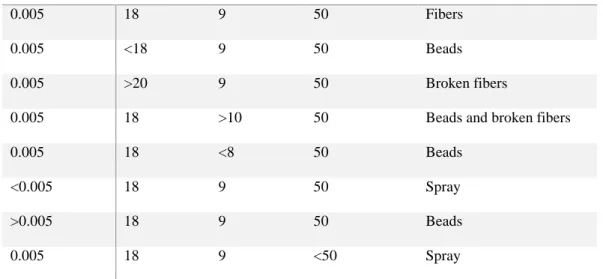
The final values obtained after optimization of these parameters and other environmental factors are reflected inTable 1 (first row).
FLOW RATE
(mL/min)
VOLTAGE
(kV)
DISTANCE
(cm)
ELR CONC.
(mg/mL)
STRUCTURE
0.005 18 9 50 Fibers
0.005 <18 9 50 Beads
0.005 >20 9 50 Broken fibers
0.005 18 >10 50 Beads and broken fibers
0.005 18 <8 50 Beads
<0.005 18 9 50 Spray
>0.005 18 9 50 Beads
0.005 18 9 <50 Spray
Table 1 Varied process conditions for the electrospinning process. First row corresponds to optimized parameters.
All experiments were carried out at a temperature of 295-298 K and 30-35% of humidity
Structures other than fibers, ranging from electrospray to thin broken fibers with beads (Table 1), were obtained
upon varying these parameters, as can be seen in Fig. 2. A continuous spray is produced below a concentration of 50
mg/mL, thus forming an amorphous layer, as can be seen in Fig. 2 A. Voltages higher than 20 kV and distances
longer than 10 cm produce a mixture of beads and broken fibers, as can be seen in Fig. 2 C. In contrast, the optimal
electrospinning parameters yield homogeneous and continuous fibers without almost no defects (Fig. 2 B and D).
11
Fig. 2 Optical microscope images of several structures obtained after varying the electrospinning conditions. A: amorphous electrosprayed layer (concentration and distance between electrodes: 25 mg/mL and 5 cm respectively). B and D: continuous ELR-click electrospun fibers (parameters shown in Table 1) and C: thin fibers and beads (applied voltage and distance between electrodes: 25 kV and 15 cm). Scale bars: 50 m.Crosslinking degree was evaluated by FTIR (see supporting info section). In agreement with reports in the literature
[41], in our IR spectra, the azide band (2100 cm-1) appears only at low percentage (10%), thus indicating a high
yield of the cross-linking reaction (around 90%). To corroborate the stability and cross-linked nature of the fibers,
all samples were maintained in cold water (277 K) for at least 12 hours to dissolve non-crosslinked samples and
leave only cross-linked fibers.
Scanning electron microscopy images (Fig. 3) showed a slight variation of the typical ribbon morphology for the
fibers observed in other studies with electrospun elastin-based materials [52-54]. Our fibers seem to blend and to
have longitudinal clefts. Thickness calculations performed using the DiameterJ plug-in from FIJI software gave an
average fiber width of 1.11±0.45 m. (Fig. 3 D).
In order to investigate the tensile properties of the electrospun scaffolds, microtensile tests were performed. Fig. 6 SI
shows the strain–stress curves of scaffolds obtained after 300 s of electrospinning. An average tensile strength at
failure value of 0.59±0.08 MPa after a maximum percentage of strain of 247.5±36.08%, with a mean Young
12
Fig. 3. Morphology and dimensions of ELR-click fibers. A (deposition time=90 s), B (deposition time=300 s) and C (deposition time=90 s): SEM micrographs of ELR-click fibers at different magnifications. Scale bars: A and B 100 m, C: 10 m. D. Statistical distribution of the fiber widths was obtained using the DiameterJ plug-in of Fiji (ImageJ). Fitting to a Gaussian distribution (continuous line) gave a mean width of 1.11±0.45 m.3.2 Oriented fibers: formation and characterization
Further optimization of the parameters previously used to fabricate randomly oriented ELR-click fibers was
performed in order to obtain oriented fibers. Aligned fibers were obtained after a careful tuning of the rotational
speed applied to a rotatory mandrel. A speed of 1.8 m/s at the mandrel surface was fixed, and fibers were collected
on two coverslips placed on the parallel, opposite faces of the collector (Fig. 1). A slower rotational speed than the
optimum value yielded unaligned fibers, and velocities higher than 2.0 m/s yielded thin and broken fibers (data not
shown).
A coherency of 83% in fiber orientation was found after analysis of the processed optical microscope and SEM
images for the aligned fibers (Fig. 4). Fibers were oriented following the rotation direction of the mandrel. The
13
standard deviation of 8.1°, as can be seen in Fig. 4 C. Thus, fibers aligned with angles of between 80° and 120° weremainly obtained. Fig. 4 B represents a color survey after analysis using the OrientationJ plug-in, with the colors
showing the coherency between oriented fibers. A red color is clearly predominant in the picture, thus meaning that
the majority of the fibers are oriented in the same direction.
Contact angle measurements were carried out for deposition times longer than 90 s to evaluate the hydrophobicity of
the scaffolds (Fig. 4 D). Samples with different fiber densities and alignments (random and oriented fibers) were
analyzed, thus suggesting an increase in the hydrophobicity of the samples with deposition time, which corresponds
to higher fiber densities. Measurements for a given deposition time include fibers with both types of alignment,
since no significant difference was found between random and oriented fibers regarding the contact angle. Contact
angles of 104.6±4.1° were found for high-density samples (deposition times longer than 300 seconds), thus
indicating a very highly hydrophobic scaffold. Even in the case of less dense samples, clearly significant differences
(p < 0.001) were found in the values of the angles (89.0±4.4°) with respect to the angles found on the coverslips
14
Fig. 4 Optical and SEM (insert) images of oriented ELR-click fibers (A). Color survey showing the directionality of the ELR-click fibers (B). Distribution of fiber orientation, data obtained using FIJI software. The dashed line corresponds to a Gaussian fitting of the experimental data (C). Contact angle values from hydrophobicity tests in samples with different fiber densities (samples with aligned and random fibers were analyzed) (D). Data are reported as mean ± SD (n = 15). Statistical analysis was evaluated by analysis of variance using the Holm–Sidak method. **p < 0.001.3.3 Dermal cell culture
3.3.1 Adhesion
The viability of typical cell lines found in skin, such as fibroblasts and keratinocytes, has been evaluated in vitro. In
order to evaluate the cytocompatibility of the ELR-click fibers, human foreskin fibroblasts (HFF-1) and HaCaT
keratinocytes were seeded on top of fiber mats. DNA was quantified after 4 hours for both cell lines in order to
evaluate the number of cells adhered to the fibers in comparison with the positive and negative controls (TCP and
BSA-blocked TCP, respectively). As can be seen from Fig. 5, both types of cells adhered to the fibers in a similar
proportion to the positive control (n.s.d.), and far above the values obtained for the negative control (p < 0.001).
Fig. 5 Adhesion histograms for keratinocytes (HaCaT cells) (A) and fibroblasts (HFF-1) (B) after 4 hours of culture on ELR-click fibers (FIBERS), positive control (TP) and negative control (TCP(BSA)). Data are reported as mean ± SD (n = 3). Statistical analysis was evaluated by performing an analysis of variance using the Holm–Sidak method. **p < 0.001; *p < 0.05; n.s.d., no significant differences.
3.3.2 Proliferation
In order to further assess the cytocompatibility of the aforementioned dermal cell lines, proliferation assays were
performed by quantifying the DNA from cells seeded on ELR-click fiber mats and on the positive and negative
15
confluence, therefore this time-point was selected as the end of the experiment in order to compare the proliferationof these two cell lines on ELR-click fiber mats and controls (positive and negative). The results are depicted in Fig.
6. HFF-1 proliferation showed no statistically significant differences between the samples and TCP at any of the
three time points. In contrast, clear differences in cell proliferation were found between the samples and the negative
controls (Fig. 6 B). A similar trend was observed in the case of HaCaT cells (Fig. 6 A), in which p values <0.05
were found after culture for three days. This difference gradually disappeared over the next four days, and no
significant differences could be observed between positive controls and samples at the end of the experiment. The
values obtained for the negative controls were far lower than for the positive controls and samples in every case.
Fig. 6 Proliferation histograms of keratinocytes (HaCaT cells) (A) and fibroblasts (HFF-1) (B) after 1, 3 and 7 days of culture on ELR-click fibers (FIBERS), positive control (TP) and negative control (TCP(BSA)). Data are reported as mean ± SD (n = 3). Statistical analysis involved an analysis of variance using the Holm–Sidak method. **p < 0.001; *p < 0.05; n.s.d., no significant differences.
3.3.3 Behavior of HFF-1 and HaCaT cells
Several experiments and analysis were performed to study the behavior and interaction of HFF-1 and HaCaT cells
with the ELR-click fibers.In a first experiment, 3000 cells/cm2 of each type were seeded separately onto fiber mats
with different fiber densitiesin order to evaluate the interaction between cells and fibers. As can be seen in Fig.7 (A,
16
scaffolds by the cells. In contrast, a lower number of fibers allows a better view of the interaction of single cells withmore isolated fibers (Fig 7 B, C, E, H and I).
Both types of cells developed their normal phenotype, as can be seen in fluorescence images (Fig.7) and histology
pictures (Fig.8). The microscopy images in Fig 7 (B, C, H and I) show how HFF-1 attaches to randomly oriented
isolated fibers and tends to follow the direction set by the fiber. Similarly, HaCaT cells attach to randomly oriented
fibers at the edges of the patch-like structure that is usually formed, as can be seen in Fig. 7 (D, E and F).
Fig. 7 Fluorescence microscopy with phalloidin (green) and DAPI (blue) staining of the cytoplasm and nucleus, respectively, in HFF-1 (A, B and C) and HaCaT cells (D and E) growing on randomly aligned fibers. Immunofluorescence staining with vinculin (red) and DAPI (blue) for the cytoplasm and nucleus, respectively, in HFF-1 cells (G and H). SEM images for HaCaT and HFF-1 cells (F and I, respectively). Cells were colored using Corel Paintshop Pro software (HFF-1 in blue and HaCaT cells in brown) for better observation. Scale bars: 50 m
Histology images and H/E and elastin staining (Fig. 8) showed that HaCaT cells grow in patch-like or mosaic-like
17
fibers and attach to them (Fig 8 D, E and F). Fig. 8 I shows a single HaCaT cell nicely attached to stained ELR-clickfibers. H/E staining images (Fig. 8 A, B, C) highlight the different behavior of HFF-1 and HaCaT cells on the
ELR-click fibers. Thus, whereas HFF-1 grows more independently until finally reaching confluence, HaCaT cells grow in
separate clusters in which confluent cells multiply, thus allowing the cluster to grow.
Fig. 8 H/E staining of HFF-1 (A, B and C) and HaCaT cells (D, E and F). Elastin staining of HaCaT cells (G, H and I), all at different magnifications. Scale bars: 50 m
The growth of these two types of cells on ELR-click fibers was recorded over 48 hours. (See videos in supporting
information). The sequences in Fig. 9 A and B depict the behavior of HFF-1 and HaCaT cells, respectively.
Unfortunately, it is difficult to get a clear idea of how these two cell lines behave when they come into contact with
ELR-click fibers from the sequences in Fig. 9, mainly due to the fact that we can only show a few snapshots from
the full video. A better idea of the movements of these two cell lines can be obtained from the videos in the
supporting information. HFF-1 attaches to the surfaces and fibers but elongates along the direction established by
18
found. Once attached, the filopodia continue to explore the fiber or the vicinity, anchoring to another fiber andspreading the cytoplasm, even stretching up to 75 µm. Fibroblast grow larger (from approximately 12 µm at the
beginning of the culture to about 100 µm when they are completely spread) and colonize the area, but with no major
displacements. Isolated HaCaT cells attach to the fibers and start to move along them, travelling relatively long
distances until another cell is contacted or the distance from the starting point is too long, at which point they tend to
divide and continue colonizing the area. In fact, a closer look at the movement of these cells shows how they leave a
series of “waymarks” along the pathway that they have followed, thus allowing them to retrace their steps. The
19
Fig. 9 Representative sequences for HFF-1 and HaCaT cells growing on random ELR-click fibers (A and Brespectively) taken from videos recorded over 48 hours. See the supporting information for further details.
In the case of oriented ELR-click fibers, HFF-1 grew aligned to the fibers, as can be seen in Fig. 10 and in video 3 in
the supporting information. In the initial stages, the cells attached to the surfaces and started to explore the
surrounding area, interacting with ELR-click fibers and spreading their cytoplasm following the direction set by the
ELR-click fibers. This behavior is not shared by HaCaT cells, which attach to and interact with the fibers but do not
elongate following a clear direction (data not shown). This type of cell tends to form the classical patch-like
structure mentioned above, colonizing the fibrous scaffold in random directions irrespective of the orientation of the
fibers. The diameter of these patch-like structures grows from around 25µm at the beginning of the culture to about
20
Fig. 10 Phalloidin and DAPI staining (green (cytoplasm) and blue (nucleus)) of oriented HFF-1 cells on ELR-click fibers. All channels are merged in A and B, whereas images C and D show the green and blue channels for cytoplasm and nucleus staining, respectively, for a better visualization of the extended morphology of the aligned HFF-1 cells. The inserts represent the orientation data for the cytoplasm and nucleus respectively. Scale bars: 50 m4 Discussion
Electrospinning has been shown to be a particularly useful technique for creating nano- and microfibers from a wide
variety of materials over the past few years. Herein we describe the fabrication of ELR microfibers with dimensions
(width of 1.11±0.45m) that perfectly fit the values reported in the literature for fibers used for biomedical
applications [55]. Both the formation of ELR fibers, a topic that has already been explored [56, 57], and the
formation of stable fibers from two different ELRs has been achieved in this work. Our ELR-click fibers are
obtained in a single-step process, with no need for any further crosslinking or fiber stabilization after the
electrospinning process, by taking advantage of click chemistry, which allows us to crosslink functionalized ELRs in
a rapid manner [41]. This is a clear step forward as it does away with the need for the crosslinking steps involving
21
multicomponent system permits the formation of fibers from a combination of at least two ELRs with differentbioactivities in a single process.
Several conditions were explored to create the ELR-click fibers and the optimized values found to be similar to the
optimal conditions found in the literature [25] (mainly a voltage of 18k V, 298 K, humidity of 35%, distance
between electrodes of 9 cm) for the production of this kind of fiber. However, one clear difference with respect to
other electrospun fibers is the solution concentration (50 mg/mL), which in the ELR-click fiber is lower than the
concentration used for the formation of fibers from other materials [23-25]. We suggest that this difference is due to
the fact that our two-component system is able to form gels by itself, in a very short time, at this concentration [41,
45]. During this electrospinning process, the click reaction takes place from the very moment that both components
come together inside the needle on their way to the collector. The solvent is evaporated during this short time and
the gel formed at the tip of the needle is stretched until a fiber is formed. The ribbon-like and wrinkled surface of the
ELR-click fibers have already been described for other kinds of electrospun fibers[64, 65] and have been associated
to a deformation mismatch between the shell and the core of the fiber during solvent evaporation, thereby resulting
in a wrinkled topography [65]. Very high contact angle values for long deposition times (>100°) indicate a marked
hydrophobicity for the scaffolds. In fact, it has been suggested [65] that the hydrophobic behavior of non-woven
mats is enhanced because wrinkling.
Furthermore, the purpose of a scaffold is not only to provide a surface for cell attachment and spreading, but also to
have mechanical stability at the defect site. Thus, a well-designed tissue engineered scaffold must provide sufficient
biomechanical support during the regeneration process. Here, the average ultimate tensile strength values obtained
for our scaffolds (0.59±0.08 MPa) agree with the ones found in the literature for fibers made of elastin or blends of
elastin and other materials [66-69]. It is important to note that the purpose of these scaffolds is not to substitute the
mature skin, but to improve skin regeneration in order to get a mature tissue.
Although Weiss and co-workers have explored the possibility of using tropoelastin-based materials for skin-tissue
engineering applications over the last decade, [54, 60], genetically engineered elastin-like polymers have not yet
been processed as fibers for use in skin regeneration. In this work, keratinocytes (HaCaT cells) and fibroblasts
ELR-22
click fibers and found to exhibit excellent adhesion and proliferation profiles, similar to those for the positivecontrols.
In low density matrices, fluorescence microscopy showed the affinity of both types of cells for the ELR-click fibers
and the spontaneous trend to follow their direction (Fig. 7). This behavior is mainly observed in fibroblast cultures
(Fig 7 B and C) due to their inherent elongated morphology, which allows them to follow the pathway marked by
the RGD-containing fibers. This trend was corroborated by the behavior of the cells recorded during culture for 48
hours. Clear differences between both cell types can be seen in the video sequences (see supporting information).
Thus, keratinocytes actively migrate along the fibers then finally retrace their steps and split into two cells. This was
repeatedly observed until a classical mosaic-like structure was formed. Fibroblasts, in contrast, tend to attach to the
fibers and elongate their cytoplasm following the pathway marked by the fibers or until they find a nearby fiber to
attach to, as can be seen in fluorescence images in Fig. 7B and 7C. This behavior was not so evident at higher fiber
densities due to the large number of points that a dense matrix offers to the cells to attach isotropically instead of
following the path of a single fiber.
Histological evaluation by hematoxylin-eosin (H/E) staining (Fig. 8) corroborated this behavior for keratinocytes,
which first attached to and followed the fibers then rapidly started to spread out, finally adopting the tile morphology
that will form part of a larger mosaic of cells. However, the preference of keratinocytes for ELR click-fibers is clear
even in these patch or mosaic-like structures, as can be seen from the cells at the borders of the mosaic-like
structure. This preference for the ELR-click fibers is clearly visible in the elastin staining histology images (Fig. 8
G, H and I), where the fibers are clearly stained and the cells at the borders of the mosaic unmistakably elongate to
attach to the closest fiber. The vinculin fluorescence immunostaining images show the cells attached to the fibers,
along with some bright red dots where this attachment is actively being established with the fiber.
In addition to randomly oriented stable fibers, we also obtained aligned fibers with a coherency of more than 80%
by way of a careful process in which the speed at the surface of a rotatory mandrel had to be adjusted to the speed of
the fiber projected from the tip of the needle. Lower than optimal rotation speeds lead to non-aligned fibers, whereas
a faster rotation speed leads to very thin and fragmented fibers. This speed at the surface of the rotatory mandrel was
adjusted to 1.8 m/s under the same fixed electrospinning conditions used to obtain non-aligned fibers. In this case,
actin-23
stained cells. This alignment involves both a cytoskeletal orientation and a nuclear alignment, as can be seen fromthe green and blue channel images after phalloidin and DAPI staining, respectively (Fig. 10 C and D). This behavior
has also been observed in other kinds of cells (human stem cells and neural stem cells) attached to poly
-caprolactone [28, 70] and poly(l-lactide) fibers [71].
Wound dressings for skin tissue engineering are one of the many applications in which electrospun scaffolds have
been used. These artificial scaffolds usually lack the desired elasticity after implantation, mainly due to two factors,
namely that electrospun fibers are made of non-elastic materials and the low elastin production and secretion by
cells during the regeneration process [72-75]. The aforementioned lack of elastin and the overproduction of collagen
fibers by fibroblasts and keratinocytes is one of the main issues responsible for the shrinkage of artificial skin
scaffolds. Therefore, the presence of elastin derivatives, such as the ELRs, might theoretically prevent this
shrinking, giving a better handling of the scaffold and providing the native elasticity to the artificial skin.
Consequently, a system that could induce the growth of keratinocytes and fibroblasts on random or aligned
ELR-fibers is a very interesting approach to create scaffolds that promote regeneration of the skin after serious injuries by
mimicking the elasticity and biological properties of this tissue. H/E and elastin staining highlighted the normal
growth and behavior of the two different cell lines, both of which developed their normal phenotype. Thus, HFF-1
grew by spreading its cytoplasm and multiplying until confluence was reached, whereas HaCaT cells grew to form
patch-like clusters that grew until a confluent layer had been obtained. Complete layers of fibroblasts and
keratinocytes were obtained on top of dense ELR-click fiber matrixes, thus highlighting the suitability of these
scaffolds for skin tissue engineering applications.
5 Conclusions
Electrospun fibers usually need a post-treatment to stabilize them. However, many of the crosslinking methods
proposed for that purpose make use of solvents or organic compounds that are harmful to cells and therefore have to
be removed prior to the subsequent use of these fibers in cell culture. Moreover, the electrospun ELR fibers reported
to date need further treatment to be stable in water solutions. Herein we have presented a system for obtaining fibers
from clickable ELRs that crosslink during the flight of the fiber from the tip of the needle to the collector electrode.
24
conditions. To the best of our knowledge, there are no reports in the literature of bi-component fibers that do notneed further crosslinking after the electrospinning process. A wrinkled fiber morphology was observed in the SEM
images, and both random and oriented fiber orientations, with a high degree of alignment and coherence, have been
produced making use of a rotational electrode. Moreover, these ELR-click fibers open up the possibility of
incorporate different functionalities into each ELR that will contribute to the final overall fiber functionality.
The cytocompatibility of these ELR-click fibers has been clearly proved by way of adhesion and proliferation
studies during in vitro experiments in which the growth of keratinocytes and fibroblasts, the two main cell lines
found in the dermis and epidermis, on the ELR-click fibers is similar and follows the same trend as for the positive
controls. The affinity of these two cell lines for the ELR-click fibers has also been proven, as can be seen from the
videos recorded for both cell types during culture. Optical fluorescence images and a histological analysis of the
growth of these two cell lines indicate the possibility of using scaffolds based on ELR-click fibers for wound
dressings in skin tissue engineering applications. Finally, we have describe the preparation of electrospun scaffolds
that can be used directly after the electrospinning process as wound dressing to cover skin damaged areas or
alternatively they can be in vitro colonized by skin cell lines to prepare an artificial skin substitute that could be
implanted in the wounded area.
Acknowledgements
This study was funded by the European Commission (ELASTISLET No 646075, BIOGEL No 642687), the
Ministerio de Economía y Competitividad of the Spanish Government (MAT2015-68901-R, MAT2016-78903-R,
PCIN-2015-010) and the Junta de Castilla y León (VA015U16).