Open source hardware based sensor platform suitable for human gait identification
12
0
0
Texto completo
(2) C. Llamas et al. / Pervasive and Mobile Computing 38 (2017) 154–165. 155. Following this methodology, the first stage of the research involves the acquisition of data needed to explore options and confirm hypotheses. Their requirements are related mainly to the flexibility and affordability of the proposal, given that the subject of study usually compels some modifications regarding the type of sensing and characteristics of the data to be acquired. For example, Ohgi reported in [4] that two prototypes were built to incorporate different kinds of sensors to the data logger. In a second stage, the development phase, an ad hoc sensor platform must be designed and produced with specific requirements related with the regular use, like wearability, power consumption and wireless connectivity. In relation to this issue, Benbasat and Paradiso hold in [5] how they tend to discard the electronic boards used in the prototype and the redesign the circuitry depending on the particular physical constraints of the system. Another example is the development shown in [6] that was designed under physical constraints of weight, waterproof and hydrodynamics given that it would be attached to a swimmer using a waist belt, while it was based in a previously developed system intended to identify the type of stroke [7] using a different experimental data acquisition platform. Every sensor platform is an investment where all requirements are not usually known in advance, so many times it must be re-engineered during the experimental phase. In [3] due the cost of hardware, an RFID simulator reader was developed and used instead of a physical RFID reader. In some cases, the projects are devised using only one sensor platform, due to the cost and complexity of its design and manufacturing, restraining, therefore, the capabilities of the experimental phase because of the requirements of the deployment phase. This paper details our findings on the architecture of a sensor platform based on open source hardware and software. This kind of foundation allows us fast prototyping, especially in the research phase, with flexible, inexpensive, general purpose hardware and software components. Nowadays, open-source interest makes possible the creation of open-source scientific devices made of free open-source software on top of open-source microcontrollers [8]. This, combined with 3D printing facilities, allows us to dispose of highly sophisticated scientific equipment while driving down the cost of research tools. The main contribution of this paper is the design and implementation of an open source sensor based platform suitable to be used in data acquisition oriented to the human gait analysis. Our proposal is general enough to be employed in a similar situation where a portable, low cost, open source and remotely operated platform would be required. Bandwidth and power consumption measures are provided based on tests with an actual prototype which can be used to assess the suitability of our proposal in some other applications. The remainder of the paper is organized as follows: Section 2 summarizes some findings about this area, and digs in the requirements of other similar initiatives. Section 3 describes the architecture and the design proposed by our team. Section 4 exposes the implementation of our system and the main performance details of it. Section 5 discusses our main findings and prospects some suggestions for the future designs. 2. State of the art Along the last years of developing of sensor networks and sensor platforms, independently of its field of application, there seems to be some agreement on the main issues and constraints of these systems. In [9] the authors list the challenges established in the development of the pervasive healthcare systems, being a main fact that several issues concern to the development of the sensor platform. Among the topics highlighted by the authors are the need of interoperability and the intention of simplifying the deployment and enhance the scalability. These goals are completely aligned with the conclusions of Akyildiz et al. [1], that stated that flexibility, affordability and flowing deployment are some the desired goals related to the success of sensor networks. Moreover, the authors identify the main constraints and requirements in the development of these systems, such as fault tolerance, scalability, cost, hardware, topology change, environment and power consumption. Lo and Yang, in [10] state that most hardware platforms for pervasive healthcare applications are proprietary designs. They hold that this lack of interoperability and standards tampers the development of pervasive sensing applications. Two directions have been followed to resolve this: propose a compact modular platform, and develop an open source based platform. One example of the design of a modular platform is reported in [5] where the modularity is the basis to overcome the problems of developing systems of sensors from scratch, sharing portions of their hardware and software infrastructure. The design of a modular sensor platform will allow us to (a) encapsulate the knowledge, (b) to reduce the repetition of circuit design, and (c) to simplify prototyping. In this particular case, the author of [5] developed a set of hardware modules or panes which could be combined to obtain the desired sensor system. They extended the modularity also to the software, where each of those panes should be associated with blocks of code (or a library) that could be included in the main code when the sensor pane was attached to the processor pane. This topic of software modularity is at the foundation of a main result in the field of networked sensors: the operating system TinyOS.1 In [11] the authors point to the lack of system software support as the main problem to cope with when gathering off-the-shelf components to build a prototype. The main contribution of [11] to this matter is the development of the tiny micro threaded operating system TinyOS. TinyOS design addresses two important restrictions: intensive concurrency and efficient modularity. The hardware chosen for the first version was the very limited ATMEL 90LS8535 4 MHz processor with 8 kB of flash memory as the program memory and 512 bytes of SRAM as data memory. The. 1 http://tinyos.net..
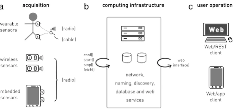
(3) 156. C. Llamas et al. / Pervasive and Mobile Computing 38 (2017) 154–165. reasons of its election were its small physical size, a modest active power load and a tiny load when inactive. TinyOS was released into the public domain under the BSD license, and is well known that this could be the main reason of its wide spreading in this area. A considerable number of sensor platforms and networks employ TinyOS as their software basis in a wide variety of application fields. One of the most representative initiatives could be the wireless sensor platform for non-invasive biomedical research SHIMMER [12]. In this work, the authors identify as a key factor to be addressed the need for heterogeneous sensing capabilities while minimizing the complexity of the hardware and software development, validation as well as to support it in order to be able to work with a platform approach where the sensing capability can be modified via physical and software device configuration. This is the role played by TinyOS. In this case, the core element of the board is the MCU of Texas Instrument MSP430 which has been widely used in wireless sensors [13]. At the present time, TinyOS runs on top of three microcontrollers: ATMEL 90LS8535, ATmega128, and Intel XScale PXA27, and is the foundation for more than 14 different sensor platforms. Another initiative, which promotes the use of open-source software in this area is DexterNet [14] which supports SPINE, an open-source signal processing library. This library installed on the body sensors and on the mobile station manages the data collection, the processing, and transmission of the data, and can be controlled via commands issued from the station. This station runs over Linux and SPINE is portable across TinyOS mote platforms. These two characteristics are fundamental to understand the evolution in the development of the sensor platforms: they are converging towards the use of open source software over a well stated and known base as TinyOS, and their interaction with systems running Linux. All these examples have in common the advantage of using open-source software, while they are restricted to use proprietary hardware. Along the last years, several initiatives of open-source hardware have been promoted. Following the definition of OSHWA (The Open Source Hardware Association),2 ‘‘Open Source Hardware (OSHW) is a term for tangible apparatus – machines, devices, or other physical things – whose design has been released to the public in such a way that anyone can make, modify, distribute, and use those things’’. As is highlighted by Rubow in [15], The Field Programmable Gate Arrays, FPGAs, permit a hardware development process that resembles closely with the software development process. This eases the updates and changes on the hardware. More and more, FPGAs are becoming a staple for hardware and embedded system designers. In 2013 the OSHWA conducted a survey to know the more important criteria considered by the practitioners in this area when using an open-source hardware component instead a proprietary one [16]. The experts regarded as the more important (a) the ability to personalize, repurpose and customize, (b) the availability of design files and documentation, and (c) the community support. These conditions also serve in our case of a sensor platform, especially in the experimental phase of the project. Although the number of users of proprietary platforms is considerable, the size of the community of the OSHW initiative is several times bigger, due to the use of general purpose software (in terms of OS and code languages and libraries) in a highly configurable hardware. One of the most successful OSHW projects has been the Arduino3 project [15,17]. Arduino is an open-source electronics platform based on easy-to-use, hardware and software. This flexibility and open source philosophy (both hardware and software) have produced a big impact on the community of designers, and the different versions of Arduino are at the core of a wide list of different types of projects. Many add-ons in the form of shields have also been produced which make possible to connect external components such as sensors and actuators. Some examples of these projects combine the Arduino and the sensors with a Raspberry Pi single board computer which can act controlling the data acquisition, processing and communications unit [18,19]. In this paper, we propose to use not only open-source software, but also open-source hardware, to build a sensor platform based on an Arduino and Raspberry Pi running Linux. This can be used in the experimental phase of a sensor based project because of its reusability and engineering flexibility, what can be taken advantage of in this kind of project, where several experiments must be done consecutively in the time, thus permitting a fast prototype development. 3. The open source hardware sensor platform Modeling systems as the one described in this work is usually made up of two main descriptive levels, a high-level one that describes the main agents of the system, their relations, functionality and other requirements; and a second more detailed one that relates the former items to hardware and software components. Specifying such kind of system is a quite an endearing task if done too abstract. In order to fulfill our demands, the design model must reflect a whole set of facilities that, for the sake of simplicity, have been split into three main parts, or layers as depicted in Fig. 1. Therefore, both the design model and the low level implementation of the system must comply a set of requirements due to the election of this structure. Concerning the non-functional description of the system, the whole system must fulfill the next requirements: (i) distribution, (ii) portability, (iii) heterogeneity and (iv) extensibility for data acquisition mechanisms. Further requirements that are also relevant are (v) resilience and (vi) openness.. 2 http://oshwa.org. 3 http://arduino.cc..
(4) C. Llamas et al. / Pervasive and Mobile Computing 38 (2017) 154–165. 157. Fig. 1. High level model of the system comprising (a) an acquisition layer, (b) a computer infrastructure layer and (c) a user operation layer.. Following this, a detailed design model is required in order to specify how the system is going to meet the aforementioned requirements through a detailed description of the technology to be used. The remainder of this section deals with a description of a use case of our system from which a high level specification is given, followed by the description of the design model. 3.1. Use case: gait data acquisition The application that our system is intended for is the acquisition of physical measures on acceleration and rotational speed involved in the human gait. The measuring will be obtained through MEM sensors attached to specific places in the locomotor apparatus of a subject of study under the form of a wearable device. This device will store the data acquired in each session until the user downloads it to a long term storage. This subject will be prompted by the conductor of the session to perform several actions and activities according to a protocol defined in the dataset specification. In order to the scenery to be the more natural as possible the study subject will not be capable to interact with the system in any way. So all the operations on the system is performed by another person that acts as the operator of the operating layer of our acquisition system. This layer must allow the operator to control the process (starting, stopping, pausing and labeling data) through a remote wireless handheld device such as a tablet with an Internet connection via WiFi. The data acquisition process would take place outside of a conventional laboratory, for example, in the dependencies of a building or even outdoors. Therefore, the system intended must face some challenges such as portability, autonomy and Internet connectivity. It is foreseeable that a session will produce a considerable amount of data in real time, then the acquisition unit must have some local storage and processing capabilities of data. At the end of such kind of sessions, the data must be dumped in a persistent storage service from the short term storage of the wearable device in order to be properly curated and exploited afterwards. 3.2. High level model Fig. 1 depicts the components of the OSHWSP (Open Source Hardware Sensor Platform) and how they are connected [20]. This high level view consists of three layers: a mobile capturing layer composed of any portable unit intended to capture field data, that we call acquisition layer; an infrastructure layer acting as broker between the acquisition layer and the rest of the system, which provides facilities needed for the internal functioning of the platform, and the operation layer, that provides control facilities for the user to acquiring data. Also, the infrastructure layer includes a stable storage for all the data acquired. Following, all the layers of the model are described starting from the operation layer. The operation layer (see Fig. 1(c)) stands for the part of the system under direct control of the user. The core functionalities of this layer deal with the usual actions on an experimental session of acquiring data [21]. A basic approach to the operation of these kind of systems must permit to start, to stop, and pause the acquisition, query the status of the subsystem and to retrieve data series to a local host. In addition, this layer would include some other secondary capabilities like the ability to add metadata to describe the conditions of the acquisition. This possibility is quite useful whenever labeling observations are required, for example regarding activity recognition. It must be emphasized that requiring that this layer interacts through Internet with the rest of the system, mainly the infrastructure layer, could be a main achievement on the usability of the overall system allowing the remote control operation in a wider scenery. This matter has a quite important effect on the design of the system. The acquisition layer comprises the terminal elements in charge of interfacing with the electronic sensors, and the sensors themselves. Any kind of sensor, in order to be usable by the system, must be integrated into this layer, at least at a logical level. This assertion seems quite obvious in the case of devices specially designed to hold sensors, but it is the consequence of a.
(5) 158. C. Llamas et al. / Pervasive and Mobile Computing 38 (2017) 154–165. convention arisen when dealing with sensors included in smartphones, tablets or laptops which could just have autonomous applications that comply with acquisition and storing necessities. The infrastructure layer (see Fig. 1(b)) plays a core part of the system providing services for the acquisition and the operation layers. In particular, it serves as a communication agent for the operation layer and as communication facilitator for the acquisition layer. First, regarding the operation layer, the infrastructure layer makes possible that the end user acts over the acquisition layer translating his/her actions performed in the operation layer, behaving this way as an agent of the user. Second, the infrastructure layer facilitates the necessary connectivity for the sensors comprised on the acquisition layer. In addition to these services, the infrastructure layer must provide a persistent storage to handle data and metadata, along with robustness in an environment of mobile communications and the Internet. 3.3. The OSHW sensor platform design Our design, while complying with the former requirements, must be specified more precisely in a detailed model when it will be implemented. The three layers of our top level model gather, each one of them, a homogeneous set of features hence helping to simplify the elicitation of the system requirements while decouples their dependencies. Data acquisition layer (Fig. 1(a)) is physically located close to the subject whose data are to be acquired; the computing infrastructure layer (Fig. 1(b)) encompasses the main functionalities ascribed to infrastructure services such as web services, database services and communication; the third layer (Fig. 1(c)) portrays end user interface related requirements, that could include web client applications, mobile applications or any other user application. A full description of each one of them is detailed as follows. 3.3.1. User operating layer Utilizing this layer the user must be able to control (start, pause, query the status or stop) the data acquisition, visualize raw data, decide when and where store data, and specify names and any other relevant metadata to the data acquisition. This facility could be oriented towards a production process or to some kind of prospective or academic target, such as preparing a biometric data corpus. Common to any use the acquisition could be aimed, an acquisition control interface and a persistent access interface are needed. Eventually, the end user will enact this kind of actions by interacting through a JavaScript enabled web front end, a mobile application or via a software user agent embedded in any other larger system. In this paper, we focus on the specification of the two inner layers and proposing an exposed interface at the computing infrastructure layer, general enough to support any other end user operation component. This design, besides complying with the former requirements, must deal with other challenges drawn from using network facilities: location and access transparency, quality of service and new fault modes. 3.3.2. Infrastructure layer The infrastructure layer provides the system with some necessary resources to ensure any necessary properties of the system such as distribution, portability, transparency, resilience and so on. Therefore, this subsystem serves as an intermediation layer between the acquisition and the user operation. Internally, this subsystem consists of stable services located in well known nodes that manage resources available to the other two layers. At the core the services offered to the operation layer are: (A.i) a unified access mechanism for the operation of the acquisition process, as for example through an ad-hoc RESTful protocol, although some other well-known standard, i.e. OPC, can be implemented; (A.ii) an intermediate data storage that permits an offline on demand retrieval of data collected on an acquisition session, alleviating the capacity and bandwidth requirements of the other two layers; (A.iii) a translation service to provide data access transparency on the basis of a common data format that could wrap raw data, time and metadata in manageable units. There exists a big sort of possible formats, ranging from low level ones like CSV, XML or JSON to other more elaborated like OPC, DirFile, CDF, Fits, and the like. In our case a plain text file formatted in CSV was implemented. The acquisition layer can benefit from the infrastructure layer in two basic sets of services: (B.i) registry and discovery services and (B.ii) connection services. Registry services are necessary for the components apart from the acquisition element in order to initiate an interaction with the rest of the system; discovering services permit the acquisition component to access some other service of the infrastructure layer. Acquisition devices with full connection capabilities are not usually found in the context of sensor platforms, apart from smartphones considered as a high level measuring device. This kind of parts has usually limited connectivity (serial line, Bluetooth, Ant, RFID) capabilities and a strong dependency from another connected device, these types of issues make connection services a key part of the infrastructure layer. 3.3.3. Acquisition layer Those devices of the system that collect the data through sensors from the physical domain and place them in a temporary storage are part of the acquisition layer. These elements use the core services of the infrastructure layer in order to perform commands such as those resulting from an end user instruction, or to write down the data into the persistent store. Therefore, these devices require a communication infrastructure so as to integrate into the system. Since there are many different ways in which a given device could be assembled into a layered communication architecture, we assume that there exists usually a protocol which integrates any component in a reasonable manner. From a.
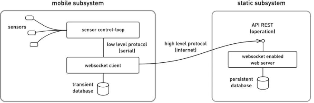
(6) C. Llamas et al. / Pervasive and Mobile Computing 38 (2017) 154–165. 159. Fig. 2. High level design of the acquisition and infrastructure layers comprising the mobile and the static subsystems of our proposal, respectively.. design viewpoint, we consider three kinds of devices: (A) full connected to Internet devices, such as smartphones; (B) limited connected devices attending the network technology, like those using Bluetooth, Zigbee, or RFID; (C) limited connected devices attending other limitation not related to the technology but due to some restriction enforced by e.g. a firewall, a router or simply an access point. At first glance, the most attainable scenery consists of devices of the type (A), due to the use of WiFi or a smartphone connectivity. Moreover, it is even possible to deploy a public component accessible from the user operation layer wherever it would be located, as may be, for example, from a simple script in a web page. 4. Implementation of the OSHW sensor platform The design of the sensor platform that we present in this paper faces two serious challenges, on the one hand it must ensure the free movement of the sensorized subject (a human being, in our case of interest) must be assured, so that the person could walk as close as possible to its natural movement, on the other hand the end user interface must be acted by an external observer that assess the validity of the data acquisition. In other words, an operator that observes the subject instructs the system to collect samples using a control panel and eventually, the system enacts on the sensor set the command to acquire data. As stated in the previous section (Section 3), our design must meet some non functional requirements, being robustness the most valuable of them. With this goal in mind, the functionality of each component of the mobile subsystem, being this element a fragile one, has been kept very simple. Therefore the exposed interface of the mobile part is a minimalist one, as it is embodied in the corresponding protocol. A pervasive non-functional requirement of our design is also a commitment with the open source requirement. Although what is open source hardware and what not is a controverted notion, as proven from controversy even in the Raspberry Pi community [22], we have tried to adhere to the most common consensus [23]. Fig. 2 depicts the high level design of the platform. This design consists of two subsystems, a portable one (a) and a permanent immobile one (b). The portable subsystem has got a WiFi adaptor in order to communicate with other hosts from the system using an ordinary communication infrastructure. In this way, the operating range of the system is, in most cases, wide enough. In any other setting, an ad-hoc WiFi network with a mobile access point can be used without a glitch. The actual portable subsystem (acquisition unit) including sensors, Arduino and Raspberry Pi assembly actually worn by a test subject is depicted in Fig. 3. In Fig. 4 the components of the system and their connection are depicted. Queried some test subjects about if the cables and the way the sensors were attached to their body could affect some perturbation in their mobility or obstruct their gait, their answers were favorable after a small period of adaption. The project is publicly available at http://percomp.github.io/oshwsp/ where the actual implementation of the system is detailed. One of the issues that posed more problems in our design were communications. Whereas the almost only noticeable complication in fully connected devices using mobile-telephony communications are moving into white spots, using an infrastructure domain WiFi network with a quite good coverage present two obvious drawbacks. First, while many institutions encourage a BYOD initiative (like Eduroam does), IoT usual devices like ours is not adequately taken into account, lacking a proper authentication domain; so that our system must be ascribed to a researcher’s identity. Second, the connection requirements that these kind of systems need could collide with the actual security policy established by the institution. Our institution offers a quite good ‘‘Eduroam’’ WiFi coverage that sticks to [24] that outlines a clearly client oriented setting with a limited service connectivity in terms of ports and type of traffic. Therefore, offering any kind of public service, like for example a RESTful API, by the mobile subsystem must be attained in an indirect way through a reciprocal connection that initiates in the infrastructure attached subsystem. In order to cope with this issue a websocket design [25], quite popular in the development of smartphone applications, has been devised. In this way, the client websocket process on the mobile subsystem (Fig. 2 (a)) issues a suitable connection request with a well-known HTTP infrastructure side service (Fig. 2(b)); on accepting this request, an upgrade request is negotiated [25]. The resulting effective communication channel is a full-duplex one, where a simple high level protocol is commanded from the static layer to the mobile layer. Regarding.
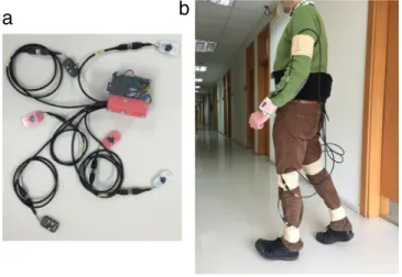
(7) 160. C. Llamas et al. / Pervasive and Mobile Computing 38 (2017) 154–165. Fig. 3. Snapshots with actual platform: (a) actual acquisition unit with wired sensors and (b) a subject attired with sensors to proceed into the acquisition phase.. Fig. 4. Connection of the elements: sensors, Arduino, Raspberry Pi, infrastructure server and user operation devices.. the interaction of both sides of the connection, an accessible protocol has been designed bearing in mind that one of the most sensitive parts in almost every distributed system is the design of the protocol. A good protocol design practice advocates for simplicity [26], so our protocol adheres to this rule through a limited set of primitives:. • • • • •. STATUS—inquire acquisition subsystem status. START—request to record data into the transient buffer. STOP—request to stop data recording and turn the transient buffer into the permanent store. The buffer is cleared. PAUSE—request to stop data recording into the transient buffer. COPY—request to copy the contents from the temporary store in the acquisition subsystem into a long term persistent data store in the static subsystem.. 4.1. Static subsystem The static part of our system stands on a workstation server connected to the Internet. With a conservative provision of several tens of Gbyte of persistent storage requirements, one mobile acquisition platform and one end user client per.
(8) C. Llamas et al. / Pervasive and Mobile Computing 38 (2017) 154–165. 161. time when creating the data corpus, almost every usual PC is capable to serve the requirements. In our case we prepared a portable PC with Ubuntu 14.04 LTS, equipped with an Intel i5 processor and a main memory with 4 Gb capacity. The operating file system partition and the user partition are formatted, respectively in ext2 and JFS. A 100 Mbps 10BaseT plug offers Internet connectivity to our system. GCC was used to develop a Web service in C Language. Special care has been taken in order to preserve a low resource consumption profile. To ease the software design task the ‘‘Mongoose’’ web development framework4 was adopted and our binary build of libMongoose is included in our project. This framework is somehow popular in the C open source community, is written in plain C Language and released by its developer with a GPLv2 license. 4.2. Mobile subsystem The basic requirements of the sensor part of our project can be summarized as follows:. • The whole platform must consist of six identical sensor units, each one of these containing a three axes digital accelerometer unit and a three axis digital gyroscope unit. Therefore, each sensor unit presents 6 degrees of freedom (6DOF) and must to be deployed on different part of the body of a study subject. • Each sensor must have a sensitivity ≥10 bits with a measuring range of ±4 g and ±1000 deg/s in its accelerometers and gyroscopes, respectively. • The sampling period Ts must be ≤10 ms. Several approaches considering the control and connection of the sensors to our platform were studied, including wireless and of-the-shelf embedded commercial and open source existing solutions. Most recent systems opt for the less intrusive sensor systems using wireless approximations as shown by Mukhopadhyay [27] using Bluetooth and alike technologies and a minimum set of sensors. However, after several back of the envelope calculations and proofs of concept with smartphones and our own hardware we intended to build a very small and affordable system that could ensure low latency round-robin communication, speed and time accuracy. Acquisition and communication facilities of the acquisition unit are deployed into two separate hardware components in order to ensure the resilience of the system to possible failures produced by the instability of software and communications. These two components are: (i) a Raspberry-Pi based device in charge of the communications with the static subsystem and the serial interface with the other component, and (ii) an Arduino UNO board with a properly wired connection shield (Arduino Proto Shield5 ) and the sensor units. Some other technologies to connect both elements were considered, mainly Bluetooth, but according to our bandwidth requirements, we opted for a wired serial communication as it will be discussed later. Obviously our proposal does not exclude other connection possibilities between these two devices. The Arduino board dialogs with the breakouts containing the sensors at a low level protocol. The joint budget of these components amounts a total of no more than EUR 60, without including the sensors. Arduino plays a fundamental role in this assembly due to its excellent features for the low level development in the communication with the sensors. In spite of this, Arduino presents several lacks regarding clock speed, storage capabilities and network communication. There exist some other successful cases in what the pairing Arduino–Raspberry Pi complements each other, resulting a more comprehensive, flexible and affordable solution [28]. In this case, the Raspberry Pi acts a base station as occurs in our proposal, for the acquisition unit, being the main difference communicating with the Arduino the use of a wireless technology. Even more, the Raspberry Pi adds some qualities concerning the usage of the acquisition unit through network delays and jitters. This allows an asynchronous mode of operation through the storage of the Raspberry Pi. There are other popular approaches with the same requirements than the combination of Arduino and Raspberry-Pi like Arduino-Yun and Arduino-Edison. Both alternatives are hybrid composite systems that merge an Arduino interface to sensors and another microcomputer in which a high level operating system acting as coordinator is deployed. For example, the Arduino-Yun platform, an Arduino UNO and an Atheros AR9331 basic configuration running OpenWrt Linux are put together on the same board. This joint system is very stable and open source, but a closed solution around a specific operating system unlike most Raspberry Pi solutions. On the other hand, a development board for Arduino-Edison, apart from software considerations, is even much more expensive (>EUR 120) than the Arduino-Yun alternative (∼EUR 80). Even more, although Arduino-Edison could be considered open source software the hardware design lacks openness. The board included in our system is made up of a Raspberry Pi B+, a USB WiFi dongle with a popular chipset (EW-7811Un) and a 8 Gb, class 4, SD card containing the Raspbian operating system (v7.0/Wheezy) and the user file system. The hardware is powered by a battery pack of modest capacity, and is configured to boot in unattended mode. Also, the initialization of the service component and the network connection to the static subsystem is fully automated. In the same way as for the static subsystem, Gcc was used to develop the software side of the system, in the purse of a portable, robust and low footprint design. This server is in charge of the dialog with the Arduino platform and coordinates these activities with the command issued by the static subsystem using the primitives settled at the end of the first part of. 4 https://code.google.com/p/mongoose/. 5 https://www.arduino.cc/en/Main/ArduinoProtoShield..
(9) 162. C. Llamas et al. / Pervasive and Mobile Computing 38 (2017) 154–165. this section. The design of the server is multithreaded, and takes advantage of shared memory and stream resources. These are needed to devise an asynchronous solution as required by the serial connection (involved in the Arduino dialog) and the Websocket protocol (needed to communicate with the Websocket server of the static subsystem). Unix facility cu was used to manage the serial connection with Arduino, which simplifies the usual serial handshake and flow control. The library ‘‘libWebsockets’’,6 was employed to assist the development of the websocket part. libWebsocket is a rare example of C Language client library to program websockets and is very appropriate, although its programming is not so straightforward like in Mongoose (which lacks this client part). Temporal and persistent storage are obtained from the local user space file system, that has proven to be fast enough for our requirements. 4.3. Data acquisition component Our solution gathers six breakouts from DroTek (Avignon, France)7 including, each one of them a MPU6000 chip from Invensense Inc. (San Jose, CA).8 MPU6000 [29] is a usual device designed for mobile systems like smartphones and tablets, and, although it is not used in our development, it has a dedicated motion processor that makes it very popular in the drone home brew community. For our purposes, MPU6000 is a 6DOF (plus a temperature sensor) unit equipped with an external SPI interface and an internal I 2 C expansion interface. Our election of this device was biased by its SPI interface that offers some advantages to our design: (i) it permits many different devices on the same physical bus, at the cost of one extra wire for each unit; (ii) it supports a quite high speed communication, up to 8 MHz for our election; (iii) with an appropriate wiring and connector allows us to wire up to 1.20 m (4 feet) at 1 MHz; and (iv) the protocol is simple and its implementation in Arduino is fast enough. USB 3.0 cables and connectors were used in our design, as shown in Fig. 4, due to the five-wire requisite of the SPI interface and also to take advantage of the shielding and quality of cable and connectors [30] employed, even though a usual USB 2.0 could be enough. Arduino and Raspberry Pi boards are actually connected through a USB serial based connection (see Fig. 4) which provides a TTY communication at 115 200 bps. Some other wireless possibilities were considered, especially using the ESP8266 module that offers a WiFi connection, and interfaces with Arduino through serial pinout connection. Some consideration prevented us to not use it: although this module can operate at 115 200 bps, it is not an enough reliable connection, losing data depending on environmental factors. Even more, it is not capable to cope with every WiFi configuration as in our case, as described in the first part of Section 4. As well as, a Raspberry Pi was intended to be very close to the subject, the more natural solution to communicate both devices could be a serial wired connection. A 115 200 bps connection is the maximum advisable standard speed for the Raspberry Pi and a quite demanding one of the control loop and timers on the Arduino side (as we could verify using the standard serial library). The Arduino code spins around the main control loop procedure loop(). In this function, the samples from the sensors are acquired and packaged into a timestamped frame (nanoseconds). This data frame is stuffed conveniently to prevent control sequences used by the serial protocol between Arduino and Raspberry Pi. Extensive tests made under these conditions allow us to ensure a steady speed of 120 frames per second with each one of them comprising a 8 byte integer timestamp and six values (accelerometers and gyroscopes samples) of 2 byte integers for each one of the six sensor units. The Arduino side sends data in binary format comprising the former bytes, start/stop codes and escape sequences giving a total of 90 bytes in case of the shortest frame. Better results could be expected by using proprietary libraries and the Atmel Studio development tools for AVR offered by Atmel. Nevertheless, although Atmel Studio is a nice and free of charge development environment, we pursue the open source hardware requirement for our design. 4.4. Experimental measures Table 1 details the power consumption of the system measured at the input of the power source. As can be seen from the data, most of the power is consumed by Raspberry-Pi component. The peak current drainage was observed mainly at boot time and when any wifi communication was observed. The Arduino subsystem drains a minimal amount of current while acquiring data. A quite typical battery with 2000 mAh would account for an autonomy of more than three hours of continuous use. In order to make use of this data acquisition device, the observed sampling frequency attainable by the system was thoroughly measured depending on the of the used USB connection baud rate and the results are presented in Table 2. To make these measures the system was tested during a lapse of time long enough to consider the statistical significance of the data acquired from the sensor units. In these experiments, were considered serial speeds from 19 200 to 115 200 bps, and in each scenery, there were read from 1 to 6 6DOF sensors. The period was calculated based on the difference of time between two consecutive samples, in microseconds, with a minimum of 1000 samples for each measure. For 6 6DOF sensors, with 19 200 bps this implied 60 s but using 115 200 bps required 8 s of readings.. 6 https://libwebsockets.org. 7 http://www.drotek.fr. 8 http://www.invensense.com..
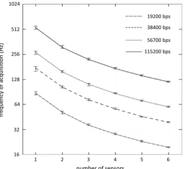
(10) C. Llamas et al. / Pervasive and Mobile Computing 38 (2017) 154–165. 163. Table 1 Voltage and current consumption measured at the power source input. Measured voltage without load: V = 5.13 V. Load. Voltage (V ). Current (I). Peak current (Ip ). Raspberry-pi Arduino Raspberry-pi + Arduino. 5.07 ± 0.04 V 5.11 ± 0.04 V 5.06 ± 0.04 V. 366 ± 20 mA 61 ± 2 mA 438 ± 20 mA. 540 ± 20 mA 72 ± 2 mA 480 ± 20 mA. Table 2 Experimental measures on sampling frequencies attainable on the system for some baud rates of the USB connection between Arduino and Raspberry Pi boards depending on the number of 6DOF sensors considered. Speed of the bus (bps). Number of 6DOF sensors. Frequency (Hz) Maximum guaranteed. Percentile 99. Maximum attainable. 19 200. 1 2 3 4 5 6. 83.61 49.31 36.27 27.86 22.89 19.62. 87.34 51.95 36.27 28.27 23.16 19.62. 91.48 53.39 37.69 29.13 23.74 20.03. 38 400. 1 2 3 4 5 6. 160.26 101.09 71.18 55.73 45.25 38.83. 174.54 103.82 72.50 56.52 46.31 39.23. 182.70 106.70 75.35 58.23 47.46 40.04. 57 600. 1 2 3 4 5 6. 255.26 154.80 106.93 86.48 70.03 59.38. 267.02 158.76 110.90 86.48 70.82 60.01. 279.40 163.28 115.21 89.09 72.57 61.25. 115 200. 1 2 3 4 5 6. 509.87 301.57 217.54 170.53 140.06 118.74. 532.08 308.74 221.61 173.01 141.58 119.92. 557.85 326.11 230.20 177.97 145.07 122.48. Table 2 shows those values admissible jointly by the API of the Raspberry Pi and Arduino. There is some evidence also on the influence of the libraries Serial and SPI available on the Arduino and the compiler. The lower the frequency of the Serial interface, the higher the delay accumulation of the sensor initialization phase. This can be related to the timers involved in the SPI bus library, and in the case of 9600 bps this totals more than 30 s, leading the Raspberry OS kernel to abort the USB Serial on the Raspberry Pi phase, due to the Arduino resetting naturally on establishing connections through USB. Anyway, as there is no reason to choose so low frequencies when there are higher ones available, this case can be left out. Fig. 5 shows the data collected in Table 2. This figure eases to check the feasibility of an experimental setting considering the number of sensors and the serial bus baud rate. In this way, it is even possible to try to extrapolate the attainable frequencies for a few more sensors in case this was necessary. Therefore, given an experimental setting with 4 6DOF sensor units and at least 50 readings per second of each one, if someone wants to use our platform could decide to use a 38 400 bps. So the control loop on the Arduino part would be freed to accomplish some other tasks as filtering, coding, or whatever needed. In relation with the influence of the baud rate to the maximum attainable acquisition frequency we can conclude that this sampling frequency is proportional to the baud rate, for a given number of sensors. However, being the number of sensors an important term in the maximum sampling frequency in each curve, to double the number of sensors does not cut in half the sampling frequency. This fact leads us to think that a limiting factor of the sampling frequency is the time consumed in the serial interface between Arduino and Raspberry Pi possibly due to limitations in the Arduino library. Using a more clever programming and software tools provided by Atmel could perhaps deliver better results. 5. Discussion and conclusions As stated in Section 1 of this paper, to deal with any kind of research project in what the gathering of physical measurements provided by sensors is a basic requirement could involve a serious problem of design and development of a software and hardware solution. This setting is especially hard to address if the sensor system must provide solid samples.
(11) 164. C. Llamas et al. / Pervasive and Mobile Computing 38 (2017) 154–165. Fig. 5. Sampling frequencies (percentile 99%) measured on the system for baud rates of the USB connection between Arduino and Raspberry Pi boards and in terms of the number of sensors to read. The vertical axis is presented in a log2 () scale. Upper bar and lower bar stand for absolute upper and lower frequencies observed in working out all the data, respectively.. and notify a condition error outcome in case of a system fault. The design and construction of such kind of system could become a challenging and time consuming stage for a usual research group given that this kind of competence is out of the area of expertise of most researchers, like in our workgroup. The experience collected in the bibliography and social network databases by the whole community of software and hardware designers and researchers state that addressing this problem poses two sequential stages: exploration (learning phase) and then utilization (developing phase) of prototypes and final systems where the key characteristics for a successful outcome are flexibility, robustness and open source design. It is well known in computing related engineering that the workplace where most interesting and fruitful solutions arise is in the domain of the open source communities in which experts present their experience and innovative ideas selflessly in the same way the traditional scientific communities do, in a better way than of the closed and proprietary environments. Open source hardware and software designs possibly does not always produce the most optimized answer to a problem, but in most cases are a key part to solve the task in a flexible manner. This paper describes a requirement model general enough for many sensor platforms in their learning phase, and also a corresponding implementation of the former model. Our platform is compound on each part of open source hardware and software and the design is conceived bearing in mind having high freedom alternatives, as can also be seen in the case of the mobile subsystem. At the sensor connection level a design adapted to a very particular task is devised, while depending on the acquisition task could have lead us to another quite different solution. The feasibility of the platform has been proved in a scenery of data acquisition related with the human gait identification. Tracing back the main milestones of this project allows us to appreciate the standing up iterative nature of the learning and developing phases, as stated in the introduction section. 5.1. Future work More work has to be done in order to obtain a more robust and capable platform. In relation with the enhance or upgrading of our system, there are many interesting hot topics that could be developed further in the future. Among the aspects we have planned to improve the platform we consider to lessen the size of the portable subsystem, and enhance the form factor upgrading processing boards with newer processors capable of working with lighter Linux versions and the integration with flexible communication mechanisms based on messaging communication middleware. Also some effort must be done to increase the bandwidth of the data acquisition while keeping low the power demand, improve its ability to be worn regarding cables and how to attach the sensors to the body, and the integration of new sensor units using the standard BLE 4.0 programming service stacks. Simultaneously, we intend to promote the construction of a collaborative dataset for human gait analysis using this system. This dataset will be usable for the open research community. Also, this could serve as an example of the advantages using open source hardware and software in collaborative projects regarding the construction of public datasets..
(12) C. Llamas et al. / Pervasive and Mobile Computing 38 (2017) 154–165. 165. Acknowledgment This work has been done in the Pervasive Computation Research Laboratory (PERCOMP Lab) at the University of Valladolid. This research received no specific grant from any funding agency in the public, commercial, or not-for-profit sectors. References [1] I. Akyildiz, W. Su, Y. Sankarasubramaniam, E. Cayirci, Wireless sensor networks: a survey, Comput. Netw. 38 (2002) 393–422. http://dx.doi.org/10. 1016/S1389-1286(01)00302-4, arXiv:1004.3164. [2] J.K. Moore, S.K. Hnat, A.J. van den Bogert, An elaborate data set on human gait and the effect of mechanical perturbations, PeerJ 3 (2015) e918. http://dx.doi.org/10.7717/peerj.918. [3] L. Ho, M. Moh, Z. Walker, T. Hamada, C.-F. Su, A prototype on RFID and sensor networks for elder healthcare: progress report, in: Proceedings of the 2005 ACM SIGCOMM workshop on Experimental Approaches to Wireless Network Design and Analysis, 2005, pp. 70–75. http://dx.doi.org/10.1145/ 1080148.1080164. [4] Y. Ohgi, 62.3: Microcomputer-based acceleration sensor device for sports biomechanics, IEEE Sensor (2002) 699–704. [5] A.Y. Benbasat, J.a. Paradiso, A compact modular wireless sensor platform, in: 2005 4th International Symposium on Information Processing in Sensor Networks, IPSN 2005 2005 (C) 2005, pp. 410–415. http://dx.doi.org/10.1109/IPSN.2005.1440958. [6] D.A. James, N. Davey, J. Hayes, From conception to reality: A wearable device for automated swimmer performance analysis, SPIE (2003) 371–378. [7] N.P. Davey, Signal analysis of accelerometry data using gravity-based modeling, Proc. SPIE 5274 (2004) 362–370. http://dx.doi.org/10.1117/12.530184. [8] J.M. Pearce, Building research equipment with free, open-source hardware, Science 337 (2012) (2012) 1303–1304. http://dx.doi.org/10.1126/science. 1228183. [9] H. Alemdar, C. Ersoy, Wireless sensor networks for healthcare: A survey, Comput. Netw. 54 (15) (2010) 2688–2710. http://dx.doi.org/10.1016/j.comnet. 2010.05.003. [10] B.P.L. Lo, G.-z. Yang, Key technical challenges and current implementations of body sensor networks, in: 2nd International Workshop on Body Sensor Networks, London, 2005. [11] J. Hill, R. Szewczyk, A. Woo, S. Hollar, D. Culler, K. Pister, System architecture directions for networked sensors, ACM SIGOPS Oper. Syst. Rev. 34 (2000) 93–104. http://dx.doi.org/10.1145/384264.379006. [12] A. Burns, B.R. Greene, M.J. McGrath, T.J. O’Shea, B. Kuris, S.M. Ayer, F. Stroiescu, V. Cionca, SHIMMER, a wireless sensor platform for noninvasive biomedical research, IEEE Sens. J. 10 (9) (2010) 1527–1534. http://dx.doi.org/10.1109/JSEN.2010.2045498. [13] B.P.L. Lo, S. Thiemjarus, R. King, Body sensor network a wireless sensor platform for pervasive healthcare monitoring, Archit. Des. 13 (2005) 77–80. http://dx.doi.org/10.1007/s11036-007-0017-1. [14] P. Kuryloski, a. Giani, R. Giannantonio, K. Gilani, R. Gravina, V.-P. Seppa, E. Seto, V. Shia, C. Wang, P. Yan, a.Y. Yang, J. Hyttinen, S. Sastry, S. Wicker, R. Bajcsy, DexterNet: An open platform for heterogeneous body sensor networks and its applications, in: 2009 Sixth International Workshop on Wearable and Implantable Body Sensor Networks http://dx.doi.org/10.1109/BSN.2009.31. [15] E. Rubow, Open source hardware: Examples of OSH projects, Int. J. Sol. Syst. Stud. (2008) 1–5. http://dx.doi.org/10.1039/b822248g. [16] OSHW community survey 2013, http://www.oshwa.org/oshw-community-survey-2013/ (accessed: 16.04.15). [17] T. Kubitza, N. Pohl, T. Dingler, S. Schneegaß, C. Weichel, A. Schmidt, Ingredients for a new wave of ubicomp products, IEEE Pervasive Comput. 12 (2013) 5–9. http://dx.doi.org/10.1109/MPRV.2013.51. [18] M. Swan, Sensor mania! the internet of things, wearable computing, objective metrics, and the quantified self 2.0, J. Sensor Actuator Netw. 1 (2012) 217–253. http://dx.doi.org/10.3390/jsan1030217. [19] Q. Li, D. Han, O. Gnawali, P. Sommer, B. Kusy, Demo abstract: Twonet - large-scale wireless sensor network testbed with dual-radio nodes, in: Proceedings of the 11th ACM Conference on Embedded Networked Sensor Systems, ACM, 2013, pp. 2–3. http://dx.doi.org/10.1145/2517351.2517440. [20] C. Llamas, K. Ottogalli, C. Hernández, M.A. González, J. Vegas, Sistema móvil basado en open source hardware para la adquisición de datos de movimiento humano, Act. J. Comput. Empotrada 2015 (2015) 109–114. [21] M. Bächlin, M. Plotnik, D. Roggen, I. Maidan, J.M. Hausdorff, N. Giladi, G. Tröster, Wearable assistant for parkinson’s disease patients with the freezing of gait symptom, Trans. Inf. Technol. Biomed. 14 (2) (2010) 436–446. http://dx.doi.org/10.1109/TITB.2009.2036165. [22] Raspberrypi is open hardware??, https://www.raspberrypi.org/forums/viewtopic.php?t=55777&p=422729 (accessed: 08.12.15). [23] Open source hardware, https://en.wikipedia.org/wiki/Open-source_hardware (accessed: 08.12.15). [24] M. Milinović, eduroam Policy Service Definition. Technischer Bericht, GEANT, 2012. [25] I. Fette, A. Melnikov, The websocket protocol, RFC 6455 (Proposed Standard) 2011. [26] G.J. Holzmann, Design and Validation of Computer Protocols, Prentice-Hall, Inc., Upper Saddle River, NJ, USA, 1991. [27] S.C. Mukhopadhyay, Wearable sensors for human activity monitoring: A review, IEEE Sens. J. 15 (3) (2015) 1321–1330. http://dx.doi.org/10.1109/ JSEN.2014.2370945. [28] S. Ferdoush, X. Li, Wireless sensor network system design using raspberry pi and arduino for environmental monitoring applications, Procedia Comput. Sci. 34 (2014) 103–110. the 9th International Conference on Future Networks and Communications (FNC’14)/The 11th International Conference on Mobile Systems and Pervasive Computing (MobiSPC’14)/Affiliated Workshops. [29] I. Inc, Mpu-6000 and mpu-6050. product specification. revision 3.4, Tech. rep., Invensense Inc. 2013. [30] Intel corporation and others, USB 3.0 specification revision 1.0 nov. 12 2008..
(13)
Figure
Documento similar
This Bachelor Thesis describes the design and implementation of Clockwork, a modular platform for the development of videogames, that consists of a microengine, a package manager, a
• An overview of the metadata management and exchange approach implemented by Open Data Support through the Open Data Interoperability Platform...
The GPSTk project is an advanced open source GNSS data processing suite initiated and supported by the Applied Research Laboratories of the University of Texas (ARL:UT), aiming
In this paper a hardware implementation of the in- stantaneous frequency of the phonocardiographic sig- nal is proposed, based on the definition given by Ville (Ville 1948) and
Indeed, given a particular notation used for the design of adaptable systems (e.g., a notation based on a suitable customization of UML [16]), the QoS assessment of models expressed
Since the Medium Access Control (MAC) layer of LTE needs to be modified to implement changes in the way LTE accesses the channel, the srsLTE plat- form is a perfect candidate
For this evaluation process, a preliminary vertical scaling system for this Monitoring platform is proposed, based on the results obtained in the previous tests as training data,
No obstante, como esta enfermedad afecta a cada persona de manera diferente, no todas las opciones de cuidado y tratamiento pueden ser apropiadas para cada individuo.. La forma
