A Hierarchical Strategy for Real-Time Tracking
On-board UAVs
Carol Mart´ınez, Pascual Campoy, Iv´an F. Mondrag´on,
Jose Luis Sanchez-Lopez, and Miguel A. Olivares-M´endez
Computer Vision Group www.vision4uav.com
Centro de Autom´atica y Rob´otica CAR UPM-CSIC
Universidad Polit´ecnica de Madrid, Jos´e Guti´errez Abascal 2, 28006 Madrid, Spain Email: [email protected]
Abstract—In this paper, we present a real-time tracking strategy based on direct methods for tracking tasks on-board UAVs, that is able to overcome problems posed by the chal-lenging conditions of the task: e.g. constant vibrations, fast 3D changes, and limited capacity on-board. The vast majority of approaches make use of feature-based methods to track objects. Nonetheless, in this paper we show that although some of these feature-based solutions are faster, direct methods can be more robust under fast 3D motions (fast changes in position), some changes in appearance, constant vibrations (without requiring any specific hardware or software for video stabilization), and situations where part of the object to track is out the field of view of the camera. The performance of the proposed strategy is evaluated with images from real-flight tests using different evaluation mechanisms (e.g. accurate position estimation using a Vicon sytem). Results show that our tracking strategy performs better than well known feature-based algorithms and well known configurations of direct methods, and that the recovered data is robust enough for vision-in-the-loop tasks.
I. INTRODUCTION
Robust visual estimation at real-time frame rates is one of the main problems when addressing the visual tracking task on-board UAVs. If this is achieved, the recovered visual infor-mation can be used in a variety of vision-based control tasks, allowing to expand the vehicle’s capabilities (e.g. vision-based landing, visual inspection), or to cope with vulnerabilities of other on-board sensors (e.g. GPS fallouts, Inertial Navigation System -INS- drift).
In previous works [1], [2], [3], we have used features-based methods [4] to track planar scenes on-board UAVs (Unmanned Aerial Vehicles). We have seen that in the application of tracking on-board UAVs (see Fig. 1), the adopted feature-based strategies are very sensitive to strong motions (e.g. vehicle vibrations and fast 3D changes), being it difficult to find a compromise between achieving real-time and accurate estimations (defining a specific number of good features to track without increasing the processing time). Although multi-resolution (MR) approaches (e.g. [5]) can help coping with strong and large motion problems, constant vehicle vibrations, a low computational capacity available on-board, and delays in the communication (when images are processed on the
Fig. 1. Tracking on-board UAVs. Robust real-time tracking allows to expand the vehicle’s capabilities using vision-based control tasks, such as landing, visual inspection, etc.; or to cope with vulnerabilities of other on-board sensors, such as GPS drop-outs or INS drift.
ground), make the MR strategies not enough to overcome these problems. Additionally, we have also observed that when using feature-based methods under strong motions, the accumulation of errors make the tracking algorithm fail after just a few frames, affecting and making on-line tests difficult.
In this paper, we present a tracking strategy based on Direct methods [6]. Direct methods have the advantages of solving, without intermediate steps, the motion of the camera and the matching of the pixels using the intensity information of all the pixels of the object to track, without identifying a special set of features.
However, in the majority of situations, feature-based meth-ods are preferable to direct methmeth-ods. This is because direct methods are based on some constraints [6] that are, in some cases, very difficult to preserve, and their speed is dependent on the number of pixels in the image template (the one that contains the object to track), being it sometimes difficult to achieve real-time frame rates.
a robust object tracking without compromising the real-time operation required in on-line applications.
In the literature, different strategies have been presented to solve the tracking problem in aerial images. Most of the strategies are based on feature-based methods [7], [8], [3], [9], [10], and just a few have explored the use of direct methods [1], [11].
This paper proposes a hierarchical strategy in terms of image resolution and number of parameters estimated in each resolution, that is able to improve the tracking task in situations where MR approaches are not enough to cope with long frame-to-frame motions. In the literature, to the authors’ knowledge, this strategy has not been presented for solving the on-line tracking problem on-board autonomous vehicles. For this reason, the intention of this paper is also to expand the use of direct methods in real-time applications.
Our strategy uses the efficient Inverse Compositional Image Alignment Algorithm ICIA [12] in a Hierarchical Multi-Parametric and Multi-Resolution framework (HMPMR-ICIA), that makes use of two hierarchical structures: the multi-resolution (MR) and the multi-parametric (MP) ones. We have successfully applied this strategy to solve our tracking problem on-board a UAV. We have found that if this strategy is adopted, it is possible to obtain robust estimations at real-time frame rates with complex motion models.
The paper is organized as follows: in Section II, we give a general idea of the visual tracking task based on direct meth-ods. Section III describes the proposed hierarchical strategy for tracking. In this section, we describe the advantages of using at the same time the MP and the MR structures. We also show the different parameters that the HMPMR strategy requires, and the HMPMR-ICIA algorithm used for tracking on-board UAVs. The performance of the HMPMR-ICIA algorithm is analyzed under different conditions in Section IV. In this section, the proposed tracking strategy is compared with well-known feature-based methods: the KLT [5] (pyramidal Lucas Kanade) and the SIFT [13] (Scale-invariant Feature Transform), and also with ground truth data obtained with a Vicon system (a vision-based motion capture system) [14]. Finally, in Section V, conclusions and the direction of future work are presented.
II. VISUALTRACKINGBASED ONDIRECTMETHODS
The 2D visual tracking task consists on determining the position of an object in the image plane, assuming that the 3D displacements of the object can be modeled by a 2D transformation (e.g translation, affine, homography [15]).
Using direct methods, this 2D position can be found, assuming that an initial position of the object is known (found manually or automatically by detection algorithms), that the motion between frames is small, that the pixels that belong to the object moves similarly, and that the appearance of the object does not change in time (the direct methods’ constraints [6]).
Therefore, the tracking task can be formulated as an incre-mental image registration task, as shown in Fig. 2.
W
W2
W3
W1
W W2
Frame 0 ( )I0 TemplateT
W0
W
Initial position ofTis known
W1
Frame 1 ( )I1
Frame 2 ( )I2 Frame 3 ( ) ...I3
Fig. 2. Tracking as an incremental image registration task.
A reference image (the object to track) is defined in the first frame. As shown in Fig. 2 (frame 0, upper left image), this reference image corresponds to a sub-image or ROI (Region of Interest), called image template (T), defined in the first frame I0 (the subscript represents the number of the frame), and found either manually or automatically by detection algorithms.
When a new frame is analyzedI1 (Fig. 2, frame 1, upper right image), the motion between the reference and the current imagesW1(Fig. 2, frame 1, green arrow) is found by an im-age registration technique, assuming that an initial estimation of the motionW0 is known (Fig. 2, frame 1, yellow arrow). When an initial estimation is not know, this initial estimation can be assumed as the identity matrix.
The estimation found between frame 0 and frame 1 (W1) is propagated as an initial guess (yellow arrow) to the next frame (Fig. 2, frame 2, button left image). The previously mentioned process is repeated: the image registration technique finds
∆W, and the motion between the reference and the current frames W2 is also found (Fig. 2, green arrow, button left image). Therefore, the motion estimations continue being propagated to the following frames.
The motion modelWrepresents the trajectory of the object in the image plane while it moves around the scene. It is a 3×3 matrix (1) parameterized by the vector of parameters
p= (p1, ...pn)T in such a way thatW is the identity matrix
when the parameters are equal to zero.
x0=W x=W(x;p)
W=
1 +p1 p2 p3
p4 1 +p5 p6
p7 p8 1
(1)
As shown in (1), W is the motion model that transforms the 2D pixel coordinates x (where x= (x, y,1)T) in image
W can model different 2D transformations with different number of parameters [15], e.g. translation (2 parameters), rotation + translation (3 parameters), similarity (4 parameters), affine (6 parameters), and homography (8 parameters). If W
represents the homography, thenk=xp7+yp8+1. Otherwise, k= 1.
In our application, the assumption of 2D motion models is enough, considering that the tracking algorithm will be used for tracking planar surfaces (building inspection, helipad for landing) or non planar surfaces that can be assumed planar when flying at high altitudes [16].
III. THEHIERARCHICALTRACKINGSTRATEGY
The proposed strategy for tracking on-board UAVs, based on direct methods, is a hierarchical parametric and multi-resolution strategy (HMPMR). It makes use of two hierarchical structures: the multi-resolution (MR) and the multi-parametric (MP) ones, as shown in Fig. 3. The MR structure is created by downsampling the images [17], [18]. Inside this pyramidal structure in resolution, the MP estimation takes place.
For each level of the pyramid, as shown in Fig. 3, a specific motion model is recovered (different motion models are estimated in each level). The idea is that the number of estimated parameters increases (i.e. the complexity of the motion model increases) with the resolution of the image, as shown in Fig. 3.
There are different advantages of integrating the MP and the MR strategies. As pointed out in [19], the MR strategy has been focused on computational efficiency and accuracy, sug-gesting the idea that at low resolutions, the vector of motion is smaller and long displacements can be better approximated by improving the estimation using higher resolution information. In a strategy using only a MR approach, the same motion model is estimated in each level of the pyramid. The higher the frame-to-frame motion is, the bigger the number of levels the MR structure requires to be able to cope with the large displacement. Nonetheless, if many levels are required, it may be possible that due to the subsampling of the image, the information at low resolutions could be not enough (de-pending on the quality and size of the images) to find a robust estimation of a motion model with a high number of parameters, presenting an unstable behavior when estimating motion models with high number of parameters.
If on the contrary, less pyramid levels are considered, in order to avoid the loss of information due to the low resolution, then this reduction of levels will cause a reduction in the range of motion the algorithm can tolerate. For these reasons, for our application, MR approaches are sometimes not enough to solve the tracking problem.
Nonetheless, by integrating the MR and the MP structures, the HMPMR approach will allow to continue taking advantage of the low resolution information to find large range of motion, with a low computational cost, even when motion models with high number of parameters are estimated. This is achieved by estimating only a few parameters (e.g. 2 parameters, translation motion model) at the highest level of the pyramid
(using the lowest resolution image), and then by increasing the complexity of the motion model with the increase of the image resolution (as shown in Fig. 3).
A. HMPMR-ICIA Algorithm
The image registration process consists in aligning two images, a reference image or image template (T) and the current image (I), by finding the transformation (W) that best aligns them. This transformation or motion model (W) is normally found iteratively, by minimizing the sum of squared differences (SSD) between the reference image and the current image [20].
The image registration algorithm we use for tracking is the Inverse Compositional Image Alignment algorithm (ICIA) proposed in [12]. It is considered an efficient algorithm for image registration (or image alignment) that permits an effi-cient estimation of the parameters that define the motion of the objectW.
The goal of the ICIA consists in finding the vector of parameterspof the motion model (1) by minimizing:
X
x
[T(W(x; ∆p))−I(W(x;p))]2 (2)
The increment of the parameters (∆p) is found after a first-order Taylor series expansion of (2). Then, the motion model is updated, as follows:
W(x;p)←W(x;p)◦W(x; ∆p)−1 (3)
The increment in the parameters ∆pof the motion model (1) is estimated iteratively until stopping criteria are reached, denoting the best local alignment solution. In our imple-mentation we have defined three criteria: the minimum is reached if the increment of the parameters is below a threshold ||∆p|| ≤10−5, if the MAE (mean absolute error) between T andI does not decrease after a defined number of iterations (10 iterations), or if the maximum number of iterations have been reached (100 iterations).
The efficiency of the ICIA algorithm comes from the change of roles of images Iand T in (2), and the way the motion model is updated (3). This change of roles makes the Hessian matrix be constant, calculated at the beginning of the tracking task, and so a fast alignment is achieved.
Nonetheless, this iterative algorithm relies on the assump-tion that a previous estimaassump-tion of the parameters of the moassump-tion model is known, and that after a linearization of the cost function (2), the algorithm iteratively solves the increment of the parameters. Nevertheless, this linearization is valid only when the range of motion is small.
|
2j
Propagation of parameters Level 2
Level 1
Level 0 Lowest
resolution level
1 p p p 1 p 0 0 1
3 6 2 4
1+p p p
p 1+p p
0 0 1 2
6 1 4
3 5
x
2j
Input:current image
Output:position of the template in current image
1 0p 0 1p 0 0 1
3 6
x 2
x 2
Highest resolution
level
Result Frame 216 Result Frame 406
... ...
Frame 216 Frame 406
W0 propagated to the next frame
Template
Template
Template
HMPMR:Hierarachical Multi-Parametric and Multi-Resolution Strategy
... ...
Multi-Resolution Structure
(MR)
Multi-Parametric Structure
(MP)
W0
= W1
= W2
=
Affine
Rotation + translation
Translation
Fig. 3. Hierarchical Tracking Strategy. A multi-parametric (MP) structure inside a multi-resolution (MR) scheme is used to improve the tracking problem
on-board UAVs, especially when the range of motion between frames is large. The MR structure is created by downsampling the images. Inside this pyramidal structure in resolution, the MP estimation takes place. Different motion models with different number of parameters are estimated in each level. The motion model found in the lowest level of the pyramid (level 0) permits to find the position of the template image in the current image. Additionally, this motion model is propagated as initial guess to the next frame.
Therefore, by using the ICIA algorithm, an efficient track-ing algorithm can be achieved ustrack-ing direct methods; and by integrating it with the HMPMR structure, robust motion estimations are achieved, allowing to track objects during long periods of time at real-time frame rates.
Algorithm 1 describes in more detail the different steps of the HMPMR structure for tracking using the ICIA algorithm. As input, the algorithm requires the information of I0 (the first frame), and the coordinates (x) in I0 of the object to track. These coordinates can be found manually or automati-cally using detection algorithms, e.g using template matching approaches [21].
Additionally, the algorithm requires the definition of the number of levels (pL) of the MR structure, and the definition of the different motion models in the MP structure (Wj). The different levels in the MR pyramid (pL) are defined as a function of the size of the template image T, so that in the lowest resolution level, i.e. thejmaxlevel (wherejrepresents the level), an image with not less than a defined number of pixels will be used. On the other hand, the definition of the motion models in the MP structure depends on different criteria: the complexity of the task, the application (building inspection, landing), and the configuration of the camera in the UAV (forwards-looking or downwards looking). However, the most important aspect to consider is that W0 i.e. the motion model in the lowest pyramid level or the highest resolution level, must be defined as the best transformation that represents the motion of the object or the motion of the camera in the image plane. Additionally, in order to ensure
the detection of large frame-to-frame motion, the translation motion model must be estimated in the highest level of the pyramid Wjmax (the level that has the lowest resolution image), and in the intermediate levels, the motion models must be selected in such a way that a smooth transition of the number of parameters from the highest to the lowest level of the pyramid is obtained.
Once this information is known, I0 is downsampled ac-cording to the different levels (pL) of the MR structure, thus creating the template imageTjfor each level, as shown in Fig. 3. Additionally, in this initialization stage, for each level of the pyramid, the Hessian matrix and its inverse are calculated, as shown in more detail in Algorithm 1, steps 1–6. These steps are carried out only once, at the beginning of the tracking task. When a new frame is analyzedI, it is first downsampled to create the MR structure, as shown in Fig. 3. The motion model at the highest level (lowest resolution) (Wjmax) is initialized.
Because this is the first frame,Wjmax is the identity matrix.
For each level of the pyramid, the HMPMR-ICIA algorithm is applied as follows:
1) The coordinatesxinTare warped usingWj, and∀x,
the error betweenT(x)andIj(Wj(x;p)), is calculated
(steps 9-11 Algorithm 1).
2) The increment of the parameters is found using step 12, Algorithm 1.
3) The motion model is updated using (3), step 3, Algo-rithm 1).
defined for that level. When the stopping conditions have been reached, the parameters are propagated to the next level of the pyramid as follows, taking into account that the images have been scaled by a factor of two:
pji−1=pji f or i={1,2,4,5}
pji−1= 2pji f or i={3,6}
pji−1= p j i
2 f or i={7,8}
(4)
being,
j={jmax, jmax−1, . . . ,0}={pL−1, pL−2, . . . ,0}
Where the subscriptirepresents the parameters defined in (1), and j represents the level of the pyramid. j is initialized as j = jmax, where jmax = pL−1, where pLis the number of levels the pyramid.
At the lowest level of the pyramid (i.e the one that has the image with the highest resolution), the motion model
W0 will contain the parameters that minimize the differences between the template and the current images, that are the best approximation to the motion of the object in the image plane. With this information, the position of T (i.e. the object to track) in the current image Ican be determined (steps 15-16 Algorithm 1).
The motion model found in this frame is propagated as initial guess to the highest level of the pyramid jmax of the next frame, as follows:
pjmax
i =p
0
i f or i= 1,2,4,5
pjmax
i =
p0 i
s f or i= 3,6 pjmax
i =sp
0
i f or i= 7,8
(5)
Wheres= 2jmax (step 8 Algorithm 1).
This propagation of the parameters from the lowest level of the pyramid in the previous frame to the highest level of the pyramid in the new frame permits to validate the linearization of (2) done by the image registration algorithm, so that when a new frame is analyzed, by using the estimation ofWin the previous frame, images T and I are close enough to find a minimum.
The pseudocode of the HMPMR-ICIA algorithm is pre-sented in Algorithm 1.
IV. RESULTS
Tests are performed using different types of images under different conditions, in which the most complex of the 2D transformation (homography) is estimated.
In the first test, a comparison of different configurations of the ICIA algorithm is conducted: the ICIA without hierarchies, the MR-ICIA, and the HMPMR-ICIA (all of them based on direct methods). In this test, we analyze the advantages of using, simultaneously, the MP and MR hierarchies during the tracking task.
input : I0,pL,I,x, configuration ofWj
output: W0, transformation that finds the position of T inI
Pre-compute
1. DownsampleI0according topLand create Tj 2. Initializejmax=pL−1
forj←jmax to 0 do
3. Evaluate the gradient∇Tj=∂∂xTj,∂∂yTj,1
4. Evaluate the Jacobian Jj =∂∂Wpj at(x,0) 5. Compute the steepest descent images SDI
SDI(x) =∇T(x)j ∂Wj ∂p
6. Compute the Hessian matrix and its inverse
Hj =P x
h
SDI(x)TSDI(x)i, andHj−1
end
Iterate
foreach new frameIdo
7. DownsampleIaccording topLto createIj
8. InitializeWjmax according to (5). If it is the first frame,Wjmax is the identity matrix
forj←jmax to 0 do
repeat
foreach xinTdo
9. Warp Wj(x;p)to find Ij(Wj(x;p))
10. Compute
Ej = [Ij(Wj(x;p))−Tj(x)] 11. Computebj =bj+SDI(x)T
Ej end
12. Compute∆p=Hj−1bj
13. Update the warp
Wj(x;p)←Wj(x;p)◦Wj(x; ∆p)−1 until||∆p|| ≤ε;
14. Propagate the parameters inWj(x;p)
to the next level using (4)
end
15. UseW0 to find the position ofTinI 16. Draw results
end
Algorithm 1:HMPMR-ICIA tracking algorithm
Videos of the tests are found in [22].
• Experimental setup
The data used in tests 1 and 2 correspond to different flights conducted with the Rotomotion SR20 electric helicopter (the Colibri III system [23]), shown in Fig. 1. The images used in test 3 correspond to a laboratory test conducted using the VICON system (a vision-based motion capture system) and a FireWire camera.
The HMPMR-ICIA and the MR-ICIA algorithms were developed inC+ +and the OpenCV libraries [21] were used for managing image data.
On the other hand, the KLT feature-based algorithm used in the second test is based on the version of the algorithm im-plemented in the OpenCV libraries. The maximum number of features was defined as100, a window size of5was used, and four pyramid levels were used in the multi-resolution structure of the algorithm. The SIFT algorithm used in test 2 is the implementation developed by Rob Hess [24], [25]. The values of the different parameters the algorithm requires correspond to the standard values that come with the implementation of the algorithm used.
A. Test 1: comparison with direct methods
In this test, we evaluate the performance of the HMPMR strategy tracking part of a structure affected by the 3D motion of the UAV. We compare the proposed HMPMR-ICIA algo-rithm with other configurations of the ICIA algoalgo-rithm: with the ICIA without hierarchies, and also with a MR-ICIA. In this test, we analyze the advantages of using, at the same time, the MR and MP hierarchies during the tracking task when large frame-to-frame motions are presented.
The object to track in the image sequence used in this test corresponds to a flat section of a 3D structure. The UAV is flying around the structure during the task. The size of the images is 640×480 pixels, the size of the template is 84×170pixels, and the number of levels of the MR structure was defined as pL = 4. The camera on-board the UAV is in a forwards-looking configuration, and the homography (8 parameters) is chosen as the transformation that best describes the changes of the scene due to the UAV movements.
Therefore, the ICIA recovers 8 parameters (the homogra-phy) i.e. no hierarchical structure is used. The MR-ICIA re-covers the same number of parameters in the different levels of the pyramid. Thus, the combination of motion models used is in the form8-8-8-8, and the HMPMR-ICIA recovers different motion models in its structure 8-4-3-2: the homography in the lowest level of the pyramid (8 parameters), the translation in the highest level (2 parameters), and the similarity (4 parameters) and rotation+translation (3 parameters) in the intermediate levels.
The selected image sequence contains jumps of the visual information, so that long frame-to-frame motions affect the object to track (sometimes 5 and 10 pixels from frame-to-frame). This characteristic makes this sequence challenging from the visual tracking point of view.
Frame 188 Frame 296
Frame 1 Frame 98
Frame 342 Frame 369
Fig. 4. Visual examination of the tracking results: ICIA. The green/light
box indicates the result of the tracking task. Without using any hierarchy, the ICIA is not able to track the template when there are large motions in the sequence (>20pixels).
In this first test, the evaluation of the results obtained with the different algorithms is based on a visual examination of the tracking results (if the green/light box is covering the tracked area during the sequence).
Fig. 4 presents the result of the tracking task using the ICIA algorithm without any hierarchy, recovering 8 parameters (the homography). The green/light box indicates the result of the tracking task.
As can be seen in Fig. 4, the ICIA was not able to continue tracking the template after frame 360. The large frame-to-frame motion in some parts of the sequence violates one of the main constraints of direct methods (small motion), and so the ICIA is not able to track the template in this sequence.
Fig. 5 presents a collection of images that shows the perfor-mance of the MR-ICIA during the tracking task (8 parameters are found in the four levels of the hierarchical structure). A green/light box indicates the results in each frame.
Analyzing Fig. 5, we can see that the MR-ICIA 8-8-8-8 configuration fails after frame 20. The MR-ICIA is not able to track the template in the image sequence. As mentioned in Section III, a multi-resolution hierarchy is not always enough in our application to solve the tracking problem when large frame-to-frame motions are presented.
Frame 1 Frame 12
Frame 20 Frame 23
Fig. 5. Visual examination of the tracking results: MR-ICIA. The green/light box indicates the result of the tracking task. As can be seen, the MR-ICIA strategy can not track the template in all the sequence.
the MR-ICIA fails earlier than the ICIA algorithm without hierarchies.
Finally, the proposed HMPMR strategy using the ICIA algorithm is tested. Fig. 6 presents a collection of images illustrating the performance of the tracking task using the HMPMR-ICIA algorithm. As can be seen, the HMPMR strat-egy is able to track the template in all the frames in spite of the jumps the sequence has and of the 3D changes of the sequence.
As a result of the different algorithms tested, we can conclude that the MR approach is not enough to overcome frame-to-frame motions that are > 5 pixels, whereas a well configured HMPMR strategy can deal with large frame-to-frame motions > 5 pixels. Additionally, we could see that the HMPMR is more robust than the MR approach recovering motion models with high numbers of parameters.
B. Test 2: comparison with feature-based methods
In the previous test, it was shown that by configuring the direct method with MR and MP hierarchies, the results of the tracking task present a more robust behavior than when using only a MR hierarchy or none of the hierarchies. As a consequence, using the ICIA algorithm with a HMPMR strategy is more robust than using only a MR approach in our application.
This second test compares the performance of the HMPMR-ICIA algorithm with two feature-based algorithms: the SIFT and the KLT (pyramidal Lucas Kanade). The comparison is also performed in the most difficult situation: when tracking planar objects that are affected by perspective effects due to the 3D movements of the UAV.
In this test, a UAV is flying around a “house” with a forwards-looking camera configuration. The front of the “house” is used as template image T. The size of the images is320×240pixels, the size of the template is213×123pixels, andpL= 4 (4 pyramid levels).
Frame 1 Frame 26
Frame 98 Frame 296
Frame 342 Frame 420
Frame 499 Frame 516
Fig. 6. Visual examination of the tracking results: HMPMR-ICIA. The
green/light box indicates the result of the tracking task. The HMPMR-ICIA tracks the template in all the sequence.
The selected sequence was chosen due to some particular features found in it that help testing the performance of the algorithms. First, the images contain constant changes in positions because of the UAV vibrations. Additionally, the sequence includes: changes in the appearance of the object to track (due to 3D movements), low texture information, and loss of information when the object goes out of the field of view (FOV) of the camera.
Taking into account the different changes in perspective through the sequence, the homography (8parameters) is cho-sen as the transformation that best describes the changes of the scene due to the UAV movements. Therefore, the combination of motion models used in the HMPMR-ICIA algorithm is 8-4-3-2: the homography in the lowest level of the pyramid (8 parameters), the translation in the highest level (2 parameters), and the similarity (4 parameters) and rotation+translation (3 parameters) in the intermediate levels.
Fig. 7 shows a collection of images illustrating the perfor-mance of the tracking task and comparing the results obtained by the three algorithms: two feature-based methods (SIFT and KLT), and one based on direct methods the HMPMR-ICIA.
SIFT KLT
Direct method Feature-based methods
HMPMR-ICIA
Frame 0
Frame 236
Frame 426
Frame 513
Frame 669
Frame 883
Frame 1000
Fig. 7. Visual examination of the tracking results: SIFT, KLT, and HMPMR. The red polygons indicate the template estimated by the feature-based methods (SIFT, first column, and KLT, second column).The green polygon indicates the position of the template estimated by the direct method HMPMR-ICIA. As can be seen, the latter is the only one that tracks the template in all the sequence.
In this figure, it can be seen that the feature-based al-gorithms (Fig. 7, first and second columns) failed tracking the template. The SIFT algorithm (first column) fails earlier than the KLT algorithm (second column), although in Fig 7, it can be seen that the KLT fails also in the first frames of the sequence. The multi-resolution structure of the KLT
tracker is not enough to help the algorithm track this sequence. Nonetheless, in Fig. 7, third column, it can be seen that the HMPMR-ICIA with the8-4-3-2 configuration tracked the template in all the frames of the sequence (third column).
The comparison of the algorithm show that after a few frames the feature based algorithms failed detecting a correct transformation. In spite of the different features found by the algorithms (an average of 80 features in the KLT, and 30 in the SIFT), the low texture information of the object to track (the template), and the previously mentioned characteristics of this sequence, makes the feature-based trackers fail.
Finally, Fig. 8 shows the average speed of the three algo-rithms expressed in FPS (frames per second). As expected, the KLT feature-based algorithm (red box) tracks the template faster (average speed 27 FPS matching ≈ 85 features per frame) than all the other methods. This algorithm is widely used in different applications because of its efficiency, al-though we have shown that its performance is not robust enough in our application to track the template appropriately. The SIFT algorithm (Fig. 8, cyan box) has an average speed of 3 FPS, obtaining the slowest speed of the different algorithms tested (this is due to the high computational overheads in the different steps of the algorithm: e.g the calculation of the descriptor for each point, matching of points, etc ).
FPS (Frames Per Second)
HMPMR-ICIA
SIFT KLT
0 5 10 15 20 25 30
Fig. 8. Speed comparison. The average fame rate of the different algorithms tested is plotted. The SIFT (cyan box), 3 FPS; the KLT (red box), 27 FPS; and the HMPMR-ICIA (blue box),16 FPS.
On the other hand, we can see that in this test the direct method HMPMR-ICIA algorithm (Fig. 8, blue box) reaches an average speed of 16 FPS. This speed is fast enough to use the visual information for a vision-in-the-loop application.
It is also important to consider that the direct method analyzes each pixel of the template in each level of the pyramid (around 26000 pixels must be analyzed only in the highest resolution level). In spite of the amount of information the algorithm analyzes, we can see that by using the MP and MR strategies at the same time, a robust real-time tracking algorithm is obtained.
C. Test 3: visual estimation for take-off and landing maneu-vers
that is better than the one obtained with feature-based methods, being able to track the object in the sequences used.
In this test, we analyze the performance of the HMPMR-ICIA algorithm tracking a template for a landing and take-off application. The vision-based estimation obtained with the HMPMR-ICIA algorithm is tested experimentally in a laboratory.
Template Vicon
landmarks
Vicon infrared camera
Coordinate Systems
Vicon Coordinate
System
Camera Coordinate System
Zc
Xc
Yc
Zvicon
Xvicon
Yvicon
FireWire camera
Helipad
Fig. 9. Experimental setup. A FireWire camera that is moved manually
simulates the UAV during take-off and landing tasks. This camera captures images of a scaled helipad. Ground truth data is generated using a Vicon system that tracks infrared landmarks located on the FireWire camera and the helipad.
As can be seen in Fig. 9, for the experiment, a scaled helipad is used as template (the object to track). A FireWire camera moves forwards and backwards simulating the take-off and landing process (from the image point of view). This camera captures the image data used in the test. It captures images of size 1024×740pixels at a frame rate of 7.5 FPS in order to generate image data with a large frame-to-frame motion.
The Vicon system [14], composed of five infrared cameras, is in charge of detecting the position and orientation of the template image (helipad) and the FireWire camera, by detecting and tracking infrared landmarks (see Fig. 9). The system provides accurate 3D position information (with sub-milimeter and sub-degree precision) of the helipad and the FireWire camera with respect to the Vicon coordinate system shown in Fig. 9, at real-time frame rates (100 Hz). This information is used as ground truth data in order to analyze the visual estimation obtained by the HMPMR-ICIA algorithm.
Fig. 10 presents a collection of images illustrating the performance of the tracking task. The green/light box indicates the results of the HMPMR-ICIA algorithm. The helipad was tracked during the entire task, in spite of the different changes in scale (e.g. see Fig. 10, frames: 0, 95, 168), the quality of the images (dark images), vibrations (the camera was moved manually), and the large frame-to-frame motion of the sequences (images were acquired at 7.5 FPS)
In order to compare the data, the homography obtained by the HMPMR-ICIA algorithm is used to estimate the 3D
Frame 0 Frame 27
Frame 52 Frame 81
Frame 95 Frame 120
Frame 125 Frame 168
Fig. 10. Visual examination of the tracking results: HMPMR-ICIA. The
green/light box indicates the estimated 2D position and extent of the helipad.
position of the FireWire camera using the method presented in [2], assuming that the camera is calibrated and that the dimension of the helipad is known. The vision-based positions are obtained with respect to the camera coordinate system, and then transformed to the Vicon coordinate system shown in Fig. 9.
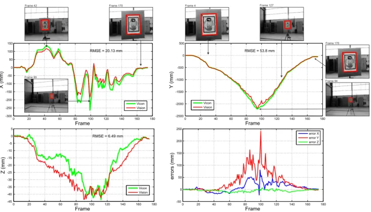
Fig. 11 (upper left and right plots, and bottom left plot) shows the comparison of the position estimation obtained by the Vicon system (green/light line) with the position estimated using the homography recovered by the HMPMR-ICIA algo-rithm (red/dark line). As can be seen, the position estimated by the HMPMR-ICIA algorithm (red/dark line) shows a behavior that is similar to the position estimated by the Vicon system (green/light line). The RMSE (Root Mean Squared Errors) obtained in the three axes are<6 cm.
0 20 40 60 80 100 120 140 160 180 -45
-40 -35 -30 -25 -20 -15 -10 -5 0 5
RMSE = 6.49 mm
Frame
Z (mm)
Vicon Vision
0 20 40 60 80 100 120 140 160 180
-50 0 50 100 150 200 250
Frame
errors (mm)
error X error Y error Z
0 20 40 60 80 100 120 140 160 180
-2500 -2000 -1500 -1000 -500 0 500
RMSE = 53.8 mm
Frame
Y
(mm)
Vicon Vision
0 20 40 60 80 100 120 140 160 180
-300 -250 -200 -150 -100 -50 0 50 100 150
RMSE = 20.13 mm
Frame
X (mm)
Vicon Vision Frame 99
Frame 170
Frame 94
Frame 42 Frame 170 Frame 4 Frame 127
Fig. 11. Comparison with Ground Truth Data. The position of the FireWire camera estimated by the Vicon system (green/light line) is used as ground truth data and is compared with the position estimated using the homography recovered by the HMPMR-ICIA algorithm (red/dark line). The bottom-right plot shows the errors obtained in each axis. Both data are expressed with respect to the Vicon coordinate system.
are around 1 m under good conditions.
Thumbnail images in Fig. 11 show the correlation of the visual data with the estimated data. These images have been manually enhanced (compared with the real ones shown in Fig. 10) to allow a clear distinction of the template image and the result of the tracking algorithm.
From this test, we can see that the homography estimated by the HMPMR-ICIA algorithm can be used for obtaining robust important information (position information) for vision-in-the-loop tasks.
V. CONCLUSIONS AND FUTURE WORK
In this paper, we have presented a hierarchical tracking algorithm HMPMR-ICIA for tracking on-board UAVs using direct methods, thus extending the use of direct methods for real-time applications. Previous works in this area have often been based on feature methods. Nonetheless, we have shown that our tracking strategy performs better than well-known feature-based algorithms (SIFT and KLT) and well-known configurations of direct methods (MR-ICIA), in the presence of strong changes in position, fast changes in appearance, situations where part of the template is out the FOV of the camera, and under constant vibrations. In the latter aspect, this is accomplished without requiring any specific hardware or software for video stabilization.
Different evaluation mechanisms were used to analyze the performance of the HMPMR-ICIA algorithm: images from real-flights, and accurate position estimation using the Vicon
system were used.
The results show a good performance of the algorithm tracking planar structures affected by perspective effects, and also show a good correlation of position data estimated using the homography obtained by the visual tracking algorithm, that validates the proposed strategy and makes it useful to provide valid vision-based data for UAV applications. We have seen that this good performance was achieved by estimating the translation in the lowest level of the pyramid (2 parameters) and increasing the complexity of the motion model until reaching the best transformation that describes the motion of the object.
Due to the amount of information that direct methods have to evaluate, these kinds of methods are not commonly used for real-time applications. Nonetheless, we have shown that by using the proposed strategy and without optimizing the code in any way, direct methods can be employed for real-time tracking, being able to achieve frequencies of 16 fps when estimating 8 parameters. It is important to notice that the speed is highly dependent on the number of parameters estimated (faster responses, 30-50 fps, are achieved when estimating motion models with a lower number of parameters). Additionally, the speed of the algorithm is dependent on the size of the template and the parameters estimated in each level of the pyramid.
that decides which levels of the MR and MP structure are evaluated. This dynamic strategy can help speeding up the algorithm. Additionally, future work will focus on using this tracking algorithm in vision-in-the-loop tasks, such as building inspection and landing.
Finally, considering the inherent appearance changes in our application when conducting outdoors operations (illumination changes), and the UAV 3D movements, future work will focus on establishing criteria in aspects such as the the update of the template and outliers rejection in order to deal with possible drift problems that emerge due to the propagation of the parameters through the image sequence, especially when the template appearance notoriously changes in the sequence.
VI. ACKNOWLEDGMENTS
The work reported in this paper is the result of several research stages conducted at the Computer Vision Group of the Universidad Polit´ecnica de Madrid. The authors would like to thank the Universidad Polit´ecnica de Madrid, the Consejer´ıa de Educaci´on de la Comunidad de Madrid, and the Fondo Social Europeo (FSE) for the Ph.D. Scholarships of some of the Authors. The authors would also like to thank the Australian Research Centre for Aerospace Automation (ARCAA) for allowing us to collect data from the Motion Caption System (Vicon). This work has been supported by the Spanish Ministry of Science under grant MICYT DPI2010-20751-C02-01.
REFERENCES
[1] Pascual Campoy, Juan F. Correa, Ivan Mondrag´on, Carol Mart´ınez,
Miguel Olivares, Luis Mej´ıas, and Jorge Artieda. Computer vision
onboard uavs for civilian tasks.Journal Intelligent and Robotic Systems, 54(1-3):105–135, 2009.
[2] Ivan F. Mondrag´on, Pascual Campoy, Carol Martinez, and Miguel. Olivares-Mendez. 3D pose estimation based on planar object tracking
for UAVs control. InProceedings of IEEE International Conference on
Robotics and Automation 2010 ICRA2010, Anchorage, AK, USA, April 2010.
[3] I.F. Mondragon, P. Campoy, J.F. Correa, and L. Mejias. Visual model feature tracking for uav control. InIntelligent Signal Processing, 2007. WISP 2007. IEEE International Symposium on, pages 1 –6, 3-5 2007. [4] Philip H. S. Torr and Andrew Zisserman. Feature based methods for
structure and motion estimation. In ICCV ’99: Proceedings of the
International Workshop on Vision Algorithms, pages 278–294, London, UK, 2000. Springer-Verlag.
[5] Jean Y. Bouguet. Pyramidal implementation of the Lucas Kanade
feature tracker: description of the algorithm. Technical report, OpenCV Document, Intel Microprocessor Research Labs, 2002.
[6] M. Irani and P. Anandan. About direct methods. In Bill Triggs, Andrew Zisserman, and Richard Szeliski, editors,Vision Algorithms: Theory and Practice, volume 1883 of Lecture Notes in Computer Science, pages 267–277. Springer Berlin / Heidelberg, 2000.
[7] Hong Zhang and Fei Yuan. Vehicle tracking based on image alignment in aerial videos. InEMMCVPR’07: Proceedings of the 6th international conference on Energy minimization methods in computer vision and pattern recognition, pages 295–302, Berlin, Heidelberg, 2007. Springer-Verlag.
[8] Saad Ali and Mubarak Shah. Cocoa - tracking in aerial imagery. In
Proc. Int. Conf. on Computer Vision, 2005.
[9] Luis Mejias, Srikanth Saripalli, Pascual Campoy, and Gaurav Sukhatme. Visual servoing approach for tracking features in urban areas using
an autonomous helicopter. In Proceedings of IEEE International
Conference on Robotics and Automation, pages 2503–2508, Orlando, Florida, May 2006.
[10] Jay Hyuk Choi, Dongjin Lee, and Hyochoong Bang. Tracking an
unknown moving target from uav: Extracting and localizing an moving target with vision sensor based on optical flow. InAutomation, Robotics and Applications (ICARA), 2011 5th International Conference on, pages 384 –389, dec. 2011.
[11] A. Dame and E. Marchand. Accurate real-time tracking using mutual
information. In IEEE Int. Symp. on Mixed and Augmented Reality,
ISMAR’10, pages 47–56, Seoul, Korea, October 2010.
[12] Simon Baker and Iain Matthews. Equivalence and efficiency of image
alignment algorithms. In Proceedings of the 2001 IEEE Conference
on Computer Vision and Pattern Recognition, volume 1, pages 1090 – 1097, December 2001.
[13] David G. Lowe. Distinctive image features from scale-invariant key-points. International Journal of Computer Vision, 60(2):91–110, 2004.
[14] Vicon Motion Systems. VICON MX digital optical motion capture
system. http://www.vicon.com, 2011.
[15] Richard Hartley and Andrew Zisserman. Multiple View Geometry in
Computer Vision. Cambridge University Press, New York, NY, USA, 2003.
[16] C. Martinez, L. Mejias, and P. Campoy. A multi-resolution image
alignment technique based on direct methods for pose estimation of
aerial vehicles. In Proceedings of the International Conference on
Digital Image Computing Techniques and Applications (DICTA), 2011, pages 542 –548, dec. 2011.
[17] C. H. Anderson, J. R. Bergen, P. J. Burt, and J. M. Ogden. Pyramid methods in image processing. RCA Engineer, vol. 29, no. 6, pp. 33-41, Nov./Dec., 1984.
[18] P. Burt and E. Adelson. The laplacian pyramid as a compact image
code. Communications, IEEE Transactions on, 31(4):532 – 540, April
1983.
[19] James R. Bergen, P. Anandan, Th J. Hanna, and Rajesh Hingorani.
Hierarchical model-based motion estimation. In Proceedings of the
European Conference on Computer Vision, pp. 237252., pages 237–252, 1992.
[20] Richard Szeliski. Image alignment and stitching: a tutorial. Found.
Trends. Comput. Graph. Vis., 2(1):1–104, 2006.
[21] Gary Bradski and Adrian Kaehler.Learning OpenCV: Computer Vision
with the OpenCV Library. O’Reilly, 2008.
[22] Videos. http://www.vision4uav.com/?q=HMPMRtracker.
[23] Computer Vision Group. Universidad Polit´ecnica de Madrid. CVG 2010. http://www.vision4uav.com/.
[24] R. Hess. SIFT feature detector implementation in C.
http://www.web.engr.oregonstate.edu/˜hess/index.html, Feb. 2007.
[25] Rob Hess. An open-source SIFT library. In Proceedings of the