Methods for Improving Escalators
Jose Ma. Cabanellas Becerra, Juan D. CJano Moreno, Berta Suarez, J.A.Chover and Jesus Felez
Universidad Politecnica de Madrid
Escuela Tecnica Superior de Ingenieros Industrials, Centro de Investigation de Tecnologias Ferroviarias, Spain
Key Words: Escalators, Simpack, Catia, multibody dynamics, polygonization
ABSTRACT
This paper presents several methods to search for improvements in escalator design. Escalators were invented more than a century ago. During this time several features have been developed although most of them have not shown any clear advantage over the conventional device. This mechanism is becoming a "commodity" product.
C1TEF is using tools to simulate and to analyze the static, kinematic and dynamic behaviour of this multibody system. We have used MATLAB, CATIA and SIMPACK software. In addition, a life prediction model based on dynamic results has been developed.
1. INTRODUCTION
The basic design of escalators has been in use for more than a century without any significant changes (Cabanellas et al. 2008).The first patent was taken out in 1859 by Nathan Ames for a revolving stairway in the form of an equilateral triangle. This design was the first idea for such a lifting mechanism.
Figure 1. Nathan Ames Revolving Stairway
The modern escalator comes from inventions which are more than one hundred years old (Strakosch 1983), and its basic design has not changed. Up to now, the mechanical design has been carried out in an experimental form; therefore, testing any changes is costly both in terms of time and money.
research and design concerning a mechanism that is becoming a commodity product. There are some models (Kwon 1998 and Kwon et al. 2005) which have been successfully developed by simulation software.
On the other hand, CITEF is seeking to develop innovations and new concepts in escalators. Some companies are developing improvements too, but there are few drastic innovations. An example of a drastic innovation is the idea to develop an escalator with variable speed (Ogura et Haruta 2002 and Miravete et Larrode 2007).
In this paper, some models are shown and described, which let the kinematic and dynamic characteristics of an escalator be evaluated.
2. DEVELOPED MODELS
2.1 Dynamic Model
2.1.1 Introduction
To make the dynamic models, we have used general-purpose multibody analysis software. In this case, the software selected was SIMPACK.
To analyse the dynamic behaviour of a multibody system with this program, firstly the problem must be defined and then the system divided into its basic mechanical components, like bodies, joints and force elements.
Figure 2. Modelling process with SIMPACK simulation software
After this, the model parameter values have to be defined: • Mass, inertia moments and centre of gravity positions • Assembly points between adjacent elements
• Stiffness, damping and friction coefficients, etc.
24 Cabanellas J. M'., Cano J. D., Suarez B., Chover J. A. & Felez J., Spain
SIMPACK has a specific module of chain dynamics, called SIMPACK CHAIN, which will be described briefly.
This module allows creating 2D chains which are composed of chain links (inner and outer links), chain wheels (one of them must be the leading wheel) and chain guides.
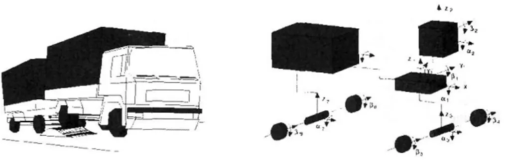
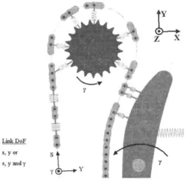
In order to design a conventional escalator, the different types of contact which occur between the different bodies depending on their relative position have to be taken into account.
LinkDoF i.yor
Figure 3. Contact Forces between Chain Links and Wheels and Guides, Degrees of Freedom and the Coordinate System
SIMPACK CHAIN models the contact between the guide and links with frictional and normal forces between the contacting bodies. In this case of contact, any individual link is modelled using the same contact parameters.
Roller Chain
i v v v ^ I
r — V W 1
Figure 4. Guide-Chain Link Contacting Forces
considered. The friction between links is due to a rotation and is therefore applied as a torque, whereby stiffness is translational and therefore generated as a force.
rttc»6 n_™co» = M'.*fflr
Figure 5. Link Contacting Forces
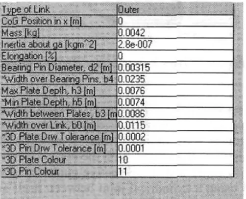
Previously, before defining the parameters that characterize different force types, all body geometries have to be determined, except for the chain. To generate a chain, some parameters have to be defined in a piecemeal manner. These parameters are located in several templates. By way of illustration, the following figure shows one of them:
Figure 6. Example of a Template used to define Outer Chain Links
As previously described, the chain definition must be highly accurate, if not, SIMPACK will not generate the chain.
Once we have explained how the SIMPACK software and SIMPACK CHAIN module work, we will describe some models which have been developed up to now. We have developed both full and partial models depending on their purposes. In addition, there are chains modelled both by and without the SIMPACK CHAIN module.
2.1.2 Full model
26 Cabanellas J. Ma., Cano J. D., Suarez B., Chover J. A. & Felez J., Spain
Table 1. Summary of the parameters of this model
Number of Links Chain Link Pitch (m)
Guide-Roller Contact Stiffness (N/m) Guide-Roller Contact Damping (Ns/m) Linear Velocity (m/s)
Gear Root Diameter (m) Gear Tip Diameter (m) Pre-load in the Chain (N)
81 0.1667
1.0 E6 500 0.5 0.8 0.963 3000
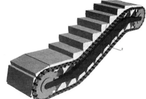
The path that the chain links have to follow is guided using some contact guides and at least two gear wheels. One of these elements has to work as a tensioner. As the figure below shows, the guide geometry can be obtained by this SIMPACK module.
Figure 7. How to Guide the Roller Chain
Nevertheless, contact forces between each roller and the real guides had to be modelled using SIMPACK basic software, because if not, the reaction force could not be calculated along the full guides. Thus, two guides were designed, one to establish the contact with the inner rollers, and the other to simulate the contact with the outer rollers. In addition, contact forces were defined between each roller and its respective guide using mobile markers. The steps were added to the model using a cylindrical joint between itself and its corresponding outer roller. The figure below shows one complete model of an escalator.
2.2 Kinematic Model
The basic mechanism of an escalator (without handrail) has been modelled using CATIA V5. A DMU KINEMATICS module has been used to simulate the overall kinematic behaviour. Although, we could have developed models only in SIMPACK, we have used both programs because it lets us compare the dynamic and kinematic behaviour between similar models. Revolute joints have been defined between links and between each link and its corresponding roller, using a common axis and a constant offset. The guides have been fixed by a rigid joint and between each roller and the corresponding guide there is a roller curve joint.
The commands and laws of motion have been defined to simulate different traction types. The model has been sensorized in order to measure the kinematic variables and relative distances between different bodies. The next figure shows the basic elements of one model developed in CATIA V5 software.
Figure 9. Basic Elements in the CA TIA V5 Model with Three Chain Links per Step
CATIA V5 is more flexible than SIMPACK in such a way that changes in the geometries are quicker to make and to test. So, different guide radiuses, roller diameters, chain link pitches and guide and step geometries have been tested.
2.3 Other Developments
Apart from developing some models based on traditional escalators, other models have been developed to test inventive ideas. So, new guide shapes and variable chain link pitches have been tested, as the following figure shows. A new guide shape has been designed in order to avoid contact between adjoining steps with two chain links per step.
Figure 10. An Example ofNon- Conventional Guide Shape with a Chain formed by Two Links per Step
28 Cabanellas J. Ma., Cano J. D., Suarez B., Chover J. A. & Felez J., Spain
effect that is due to the difference between the arc length where each chain link is located and its chain link pitch. These differences increase with the length of the chain link pitch (Calero et Carta 1999), and decrease if the radius of the wheel rises. The equation (1) shows the variation of the linear velocity with the turned angle:
v =
L • cos(<p) • co
2»sin(ar)
= R• cos{<p)•co <pe [0,2a] (i)If L is the chain link pitch, -a is the angle between two adjacent rollers and the centre of the
wheel. ^ is a variable angle defined between the vertical line and the line between the roller that is being studied and the centre of the wheel, R is the radius of the wheel, and ^ is the rotation velocity of the wheel. These parameters are shown in the following figure:
J) ©
Figure 11. Parameters to Define the Polygonization Effect in a Roller Chain
This effect also justifies the search for new guide shapes if chain link pitch rises. There ai-some patents about pulse-free guide curves.
Static, kinematic and geometric calculus with MATLAB has been programmed. The results obtained have been used as input for the other software and to compare with these software results.
3 RESULTS
3.1 Dynamic Results
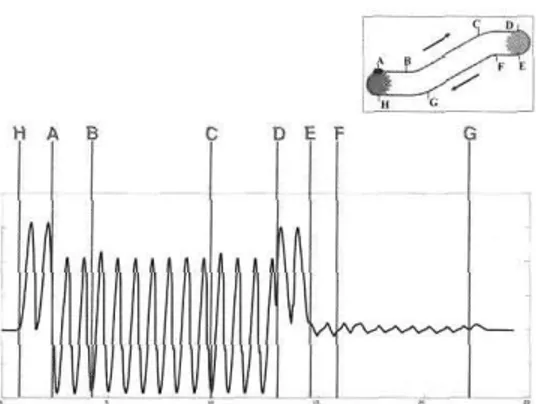
The Dynamic Results have been obtained from SIMPACK. post-processor. The following figures represent the overall dynamic behaviour of a traditional escalator designed as indicated previously.
related to the life of the chains. The following figure shows the longitudinal (tensile) force during one cycle.
•C1 B C D E F
\^*^^**vvv
AAMvxW
Figure 12. Longitudinal Force of one Chain Link
The figure below illustrates the contact forces between each roller and its corresponding guide. This figure above shows only the contact force to the inner roller and, below, the reactions to both inner and outer rollers.
25 30
time [s]
Figure 13. Contact Forces of both Inner and Outer Roller
3.2 Kinematic Results
30 Cabanellas J. Ma., Cano J. D., Suarez B., Chover J. A. & Felez J., Spain
Linear traction has been simulated imposing a constant linear velocity of one outer roller before the guide twirls. This graph shows a simulation of around 3.25 seconds, and the roller that comes from a horizontal guide part goes to the next horizontal zone.
Figure 14. Linear Velocity of a roller moved by Linear Traction in the Top Horizontal Zone using Constant Radius Guides and One Link per Step
If constant linear velocity is imposed on a roller (driving roller), the next two adjacent rollers have a linear velocity that is shown in the figure below. In addition, this figure displays the minimum distance between two adjacent steps over time. This simulation has been made for the guide shape shown below.
Diivimj N o w
Figure 15. Linear Velocity (m/s) of Rollers Moved by One Roller Following a New Guide Shape using Two Links per Step (above), Minimum Distance (mm.) Between
Driving and First Rollers (below).
Figure 16. Linear Velocity (m/s) of Rollers Moved by Linear Traction, using one Chain Link per Step
4 DISCUSSION
Escalator mechanical behaviour uao ueen studied by the three kinds of developed software, SIMPACK, CATIA and MATLAB. Each model supplies results that show different characteristics of the mechanism. All characteristics are coherent with the others.
Analogies found between the three tools used give a major certainty to the results obtained. So, figures 12, 14 and 16 show a common pattern between one another, because all of these characteristics define longitudinal phenomena: the tensile force of a chain link and the linear velocity of the rollers. It is clear that main frequency concurs with chain link pitch. The figures obtained from SIMPACK software fluctuate into higher frequencies. This phenomenon is due to the fact that SIMPACK simulates dynamic parameters, while CATIA and MATLAB models are only kinematic or static. SIMPACK results show the transitory dynamic effects during the first instants of time. Permanent components are reached quickly.
Figures 14 to 16 show that the maximum linear velocity and polygonization effect depend on certain parameters such as traction type, number of chain links per step and guide radius and guide shape.
As figure 13 shows, the reaction force withstood by each roller is very different. The inner roller withstands a lower normal force than the outer one. This is an expected result because the inner rollers are not connected as a chain. There are two different causes of normal force:
• Gravity forces due to weight which load each roller.
• Equilibrium between the tensile forces supported by chain links.
32 Cabanellas J. Ma., Cano J. D., Suarez B., Chover J. A. & Felez J., Spain
minimize these effects. Figure 16 illustrates the difference between using pulse-free or circular guides (figure 14).
Figure 17. Linear Velocity (tn/s) of Rollers Moved by Linear Traction, using one Chain Link per Step and Free-Pulse Guide
5 CONCLUSIONS
CITEF has developed a set of tools that allow studying the dynamics and kinematics of escalators. With these tools some aspects of escalators have been tested, like chain link lengths, and guide geometries, which are very important in dynamic and kinematic results. These results indicate some ways of improving escalator behaviour. The tools will be completely validated with the experimental data that is to be obtained from a real prototype. CITEF will then be able to test its innovations using these tools.
6 REFERENCES (Paper)
Cabanellas, J.Ma, Cano, J.D., Suarez, B., Chover, J.A., Felez, J. (2008). Mejora de un diseno
de mas de 100 anos. Nuevos conceptos en escaleras mecanicas. Anales de Ingenieria Mecanica, Revista de la Asociacion Espanola de Ingenieria Mecanica, Vol.1, pp. 233-239 (Chapter in a book)
Strakosch, G.R. (1983). Vertical Transportation: Elevators and Escalators, John Wiley & Sons (Ed.), pp. 194-220.
(Paper)
Kwon, Y.S. (1998). Dynamic Analysis Step-by-Step. Mechanical Engineering-CIME. (Paper)
Kwon, Y.S., Scott, G., Park, N. (2005). A Multibody Dynamic Model for Escalator Handrail Systems and its Application to Dynamic Characteristics. Springer, Multibody System Dynamics, Vol. 13, N° 2, pp. 253-266.
Ogura, M., Haruta, Y. (2002). Escalators with High-Speed Inclined Sections, Mitsubishi Electric Advance, Vol. 99, pp. 22.
(Chapter in a book)
Miravete, A., Larrode, E. (2007). Elevadores: Principios e Innovaciones, Reverte (Ed.), pp.285-389.
(Chapter in a book)
Calero, R., Carta, J.A. (1999). Fundamentos de Mecanismos y Maquinas para Ingenieros, McGraw-Hill (Ed.), pp. 269-286.
7 BIOGRAPHICAL DETAILS
Jose Maria Cabanellas is Associate Professor in the Mechanical and Manufacturing Engineering Department of the Universidad Politecnica de Madrid. His Ph.D. Thesis was on System Modelling and Simulation like the major projects that he manages in CITEF.
Juan David Cano works as Research Engineer in CITEF. He is specialized in escalator simulation and design. He received his Master's Degree in Mechanical Engineering from the Universidad Politecnica de Madrid. At present he is preparing his Ph. D Thesis.
Berta Suarez is head of the area of Railway Dynamics in CITEF. She received her Master's degree in Mechanical Engineering from the Universidad Politecnica de Madrid. At present she is preparing her Ph. D Thesis.
Jose Antonio Chover works as Research Engineer in CITEF. He is specialized in railway mechanical systems simulation and design. He received his Master's Degree in Mechanical Engineering from the Universidad Politecnica de Madrid. At present he is preparing his Ph. D Thesis.