EVALUACIÓN FINAL
PRUEBA DE HABILIDADES PRÁCTICAS CCNP
MARCO LEONARDO MORA BARRETO
UNIVERSIDAD NACIONAL ABIERTA Y A DISTANCIA – UNAD INGENIERÍA ELECTRÓNICA
DIPLOMADO CISCO CCNP YOPAL-CASANARE
EVALUACIÓN PRUEBA DE HABILIDADES PRÁCTICAS CCNP
MARCO LEONARDO MORA BARRETO
Diplomado de Profundización cisco CCNP prueba de Habilidades prácticas
Gerardo Granados Acuña Magíster en Telemática
UNIVERSIDAD NACIONAL ABIERTA Y A DISTANCIA – UNAD INGENIERÍA ELECTRÓNICA
DIPLOMADO CISCO CCNP YOPAL-CASANARE
3
NOTA DE ACEPTACION ______________________________ ______________________________ ______________________________ ______________________________ ______________________________ ______________________________ ______________________________
______________________________ Presidente del jurado
______________________________ Jurado
______________________________ Jurado
Contenido
GLOSARIO ... 7
RESUMEN ... 8
INTRODUCCIÓN ... 9
ESCENARIO 1 ... 10
ESCENARIO 2 ... 19
ESCENARIO 3 ... 34
CONCLUSIONES ... 51
5
Lista de Ilustraciones
Ilustración 1. Escenario 1 ... 10
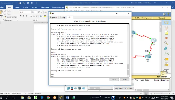
Ilustración 2. Comando show IP route en R3 ... 17
Ilustración 3. Comando show IP route en R5 ... 18
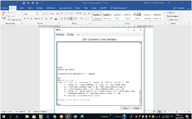
Ilustración 4. Comando show IP en R1 ... 19
Ilustración 5. Escenario 2 ... 19
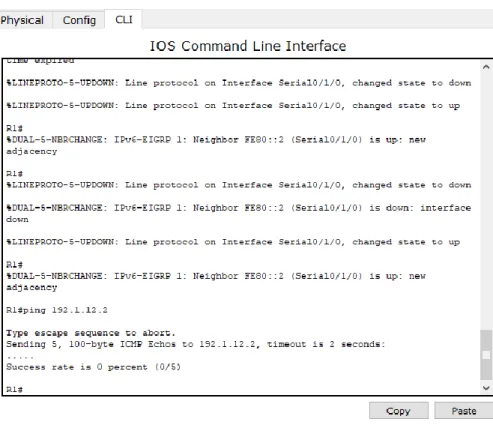
Ilustración 6. Relación BGP establecida ... 26
Ilustración 7. Relación BGP en R2 ... 27
Ilustración 8. Configuración BGP R4 ... 31
Ilustración 9. Creación de la ruta estática R3 ... 32
Ilustración 10. Creación de la ruta estática en R4... 32
Ilustración 11. Funcionamiento de conexión establecida en R3 ... 33
Ilustración 12. Funcionamiento de conexión establecida en R4 ... 33
Ilustración 13. Escenario 3 ... 34
Ilustración 14. Comando show interfaces trunk SWT1 ... 37
Ilustración 15. Comando show interfaces trunk en SWT1 ... 38
Ilustración 16. Enlace trunk en SWT2 ... 39
Ilustración 17. Verificación de VLSN ... 41
Ilustración 18. IP configuration PC3 ... 43
Ilustración 19. IP configuration PC4 ... 44
Ilustración 20. IP configuration en PC5 ... 44
Ilustración 21. IP configuration PC 6 ... 46
Ilustración 22. IP configuration PC7 ... 46
Ilustración 23. IP configuration PC8 ... 47
Ilustración 24. Ping PC1 ... 50
Lista de Tablas
7 GLOSARIO
Certificación CISCO: La certificación Cisco es un plan de capacitación en tecnología de redes informáticas que la empresa Cisco ofrece. Se divide en tres niveles, de menor a mayor complejidad: Cisco Certified Network Associate, Cisco Certified Network Professional y Cisco Certified Internetwork Expert, más conocidas por sus siglas: CCNA, CCNP y CCIE.
CISCO PACKET TRACER: Es un programa de simulación de redes que permite a los estudiantes experimentar con el comportamiento de la red y resolver preguntas del tipo ¿qué pasaría si...?
Networking: Es una red de computadoras, también llamada red de ordenadores, red de comunicaciones de datos o red informática conjunto de equipos informáticos y software reconectados entre sí por medio de dispositivos físicos que envían y reciben impulsos eléctricos, ondas electromagnéticas o cualquier otro medio para el transporte de datos, con la finalidad de compartir información, recursos y ofrecer servicios.
Switch: Es un dispositivo de propósito especial diseñado para resolver problemas de rendimiento en la red, debido a anchos de banda pequeños y embotellamientos. El switch puede agregar mayor ancho de banda, acelerar la salida de paquetes, reducir tiempo de espera y bajar el costo por puerto.
RESUMEN
El presente trabajo hace parte del Diplomado de profundización CISCO, en el que se presentan tres escenarios para ser desarrollados. Con este análisis de la información, podemos identificar nuestras debilidades y habilidades que a lo largo del diplomado adquirimos. Se hace por ende necesario que se apliquen los conceptos que se adquirieron en módulos pasados de CISCO, como son, Principios de enrutamiento, VLAN, seguridad, protocolos avanzados entre otros.
En este trabajo hice uso del programa CISCO PACKET TRACER como herramienta de simulación de los escenarios, ya que me parece la mejor herramienta para desarrollar el trabajo.
9
INTRODUCCIÓN
ESCENARIO 1
1. Aplique las configuraciones iniciales y los protocolos de enrutamiento para los routers R1, R2, R3, R4 y R5 según el diagrama. No asigne passwords en los routers. Configurar las interfaces con las direcciones que se muestran en la topología de red.
Configuración de interfaces para cada Router:
Router 1 – R1
Router> en Router#conf t
Router(config)# Hostname R1 R1(config)# end
11 R1# conf t
R1(config)# int s0/0/0
R1(config-if)#ip address 10.103.12.1 255.255.255.0 R1(config-if)#clock rate 64000
R1(config-if)#no shutdown R1(config-if)#exit
R1(config)#
Router 2 - R2: Router>en Router#conf Router(config)#hostname R2 R2(config)#end R2#conf t R2(config)#int s0/0/0
R2(config-if)#ip address 10.103.12.2 255.255.255.0 R2(config-if)#no shutdown
R2(config-if)#exit R2(config)#int s0/0/1
R2(config-if)#ip address 10.103.23.1 255.255.255.0 R2(config-if)#clock rate 64000
R2(config-if)#no shutodwn R2(config-if)#exit
Router 3 - R3 Router>en Router#conf t Router(config)#hostname R3 R3(config)#end R3#conf t R3(config)#int s0/0/0
R3(config-if)#ip address 10.103.23.2 255.255.255.0 R3(config-if)#no shutdown
R3(config-if)#exit R3(config)#int s0/0/1
R3(config-if)#ip address 172.29.34.1 255.255.255.0 R3(config-if)#clock rate 64000
R3(config-if)#no shutdown R3(config-if)#exit
R3(config)#
Router 4 – R4
Router>en Router#conf t Router(config)#hostname R4 R4(config)#end R4#conf t R4(config)#int s0/0/0
13 R4(config-if)#no shutdown
R4(config-if)#exit R4(config)#int s0/0/1
R4(config-if)#ip address 172.29.45.1 255.255.255.0 R4(config-if)#clock rate 64000
R4(config-if)#no shutdown R4(config-if)#exit
R4(config)#
Router 5 – R5
Router>en Router#conf t
Router(config)#hostname R5 R5(config)#end
R5#conf t
R5(config)#int s0/0/0
R5(config-if)#ip address 172.29.45.2 255.255.255.0 R5(config-if)#no shutdown
2. Cree cuatro nuevas interfaces de Loopback en R1 utilizando la asignación de direcciones 10.1.0.0/22 y configure esas interfaces para participar en el área 0 de OSPF.
R1#conf t
Enter configuration commands, one per line. End with CNTL/Z. R1(config)#int Lo1
%LINK-5-CHANGED: Interface Loopback1, changed state to up R1(config-if)#ip address 10.1.0.1 255.255.252.0
R1(config-if)#exit R1(config)#int Lo2
%LINK-5-CHANGED: Interface Loopback2, changed state to up R1(config-if)#ip address 10.1.0.2 255.255.252.0
% 10.1.0.0 overlaps with Loopback1 R1(config-if)#exit
R1(config)#int Lo3
%LINK-5-CHANGED: Interface Loopback3, changed state to up
%LINEPROTO-5-UPDOWN: Line protocol on Interface Loopback3, changed state to up
R1(config-if)#ip address 10.1.0.3 255.255.252.0 % 10.1.0.0 overlaps with Loopback1
R1(config-if)#exit R1(config)#int Lo4 R1(config-if)#
%LINK-5-CHANGED: Interface Loopback4, changed state to up
15 R1(config-if)#ip address 10.1.0.4 255.255.252.0 % 10.1.0.0 overlaps with Loopback1
R1(config-router)#exit R1(config)#end
R1# %SYS-5-CONFIG_I: Configured from console by console
3. Cree cuatro nuevas interfaces de Loopback en R5 utilizando la asignación de direcciones 172.5.0.0/22 y configure esas interfaces para participar en el Sistema Autónomo EIGRP 10.
R5#conf t
Enter configuration commands, one per line. End with CNTL/Z. R5(config)#int Lo1
R5(config-if)#
%LINK-5-CHANGED: Interface Loopback1, changed state to up
%LINEPROTO-5-UPDOWN: Line protocol on Interface Loopback1, changed state to up
R5(config-if)#ip address 172.5.0.1 255.255.252.0 R5(config-if)#exit
R5(config)#int Lo2 R5(config-if)#
%LINK-5-CHANGED: Interface Loopback2, changed state to up
%LINEPROTO-5-UPDOWN: Line protocol on Interface Loopback2, changed state to up
R5(config-if)#ip address 172.5.0.2 255.255.252.0 % 172.5.0.0 overlaps with Loopback1
R5(config-if)#
%LINK-5-CHANGED: Interface Loopback3, changed state to up
%LINEPROTO-5-UPDOWN: Line protocol on Interface Loopback3, changed state to up
R5(config-if)#ip address 172.5.0.3 255.255.252.0 % 172.5.0.0 overlaps with Loopback1
R5(config-if)#exit R5(config)#int Lo4 R5(config-if)#
%LINK-5-CHANGED: Interface Loopback4, changed state to up
%LINEPROTO-5-UPDOWN: Line protocol on Interface Loopback4, changed state to up
R5(config-if)#ip address 172.5.0.4 255.255.252.0 % 172.5.0.0 overlaps with Loopback1
R5(config-if)#exit
R5(config)#router eigrp 10
R5(config-router)#no auto-summary
R5(config-router)#network 172.5.0.0 0.0.3.255 R5(config-router)#exit
R5(config)#end R5#
17
4. Analice la tabla de enrutamiento de R3 y verifique que R3 está aprendiendo las nuevas interfaces de Loopback mediante el comando show ip route.
Ilustración 2. Comando show IP route en R3
5. Configure R3 para redistribuir las rutas EIGRP en OSPF usando el costo de 50000 y luego redistribuya las rutas OSPF en EIGRP usando un ancho de banda T1 y 20,000 microsegundos de retardo.
R3>en R3#conf t
Enter configuration commands, one per line. End with CNTL/Z. R3(config)#router eigrp 10
R3(config-router)#redistribute ospf 1 metric 10000 100 255 1 1500 R3(config-router)#network 172.5.0.0 0.0.3.255
R3(config-router)#auto-summary R3(config-router)#exit
R3(config-router)#log-adjacency-changes R3(config-router)#redistribute eigrp 10 subnets R3(config-router)#network 10.1.0.0 0.0.3.255 area 0 R3(config-router)#exit
R3(config)#
6. Verifique en R1 y R5 que las rutas del sistema autónomo opuesto existen en su tabla de enrutamiento mediante el comando show ip route.
19
Ilustración 4. Comando show IP en R1
ESCENARIO 2
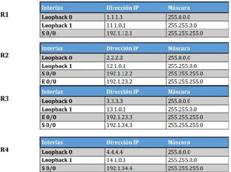
Tabla 1. Direccionamiento de Routers
1. Configure una relación de vecino BGP entre R1 y R2. R1 debe estar en AS1 y R2 debe estar en AS2. Anuncie las direcciones de Loopback en BGP. Codifique los ID para los routers BGP como 11.11.11.11 para R1 y como 22.22.22.22 para R2. Presente el paso a con los comandos utilizados y la salida del comando show ip route.
R1
Router>en Router#conf t
Enter configuration commands, one per line. End with CNTL/Z. Router(config)#hostname R1
R1(config)#end R1#
%SYS-5-CONFIG_I: Configured from console by console R1#conf t
21 R1(config)#int s0/0/0
R1(config-if)#ip address 192.1.12.1 255.255.255.0 R1(config-if)#clock rate 64000
R1(config-if)#no shutdown
%LINK-5-CHANGED: Interface Serial0/0/0, changed state to down R1(config-if)#exit
R1(config)#int Lo0 R1(config-if)#
%LINK-5-CHANGED: Interface Loopback0, changed state to up
%LINEPROTO-5-UPDOWN: Line protocol on Interface Loopback0, changed state to up
R1(config-if)#ip address 1.1.1.1 255.0.0.0 R1(config-if)#exit
R1(config)#int Lo1 R1(config-if)#
%LINK-5-CHANGED: Interface Loopback1, changed state to up
%LINEPROTO-5-UPDOWN: Line protocol on Interface Loopback1, changed state to up
R1(config-if)#ip address 11.1.0.1 255.255.0.0 R1(config-if)#exit
R1(config)#
R2
Router>en Router#conf t
Enter configuration commands, one per line. End with CNTL/Z. Router(config)#hostname R2
R2#
%SYS-5-CONFIG_I: Configured from console by console R2#conf t
Enter configuration commands, one per line. End with CNTL/Z. R2(config)#int Lo0
R2(config-if)#
%LINK-5-CHANGED: Interface Loopback0, changed state to up
%LINEPROTO-5-UPDOWN: Line protocol on Interface Loopback0, changed state to up
R2(config-if)#ip address 2.2.2.2 255.0.0.0 R2(config-if)#exit
R2(config)#int Lo1 R2(config-if)#
%LINK-5-CHANGED: Interface Loopback1, changed state to up
%LINEPROTO-5-UPDOWN: Line protocol on Interface Loopback1, changed state to up
R2(config-if)#ip address 12.1.0.1 255.255.0.0 R2(config-if)#exit
R2(config)#int s0/0/0
R2(config-if)#ip address 192.1.12.2 255.255.255.0 R2(config-if)#no shutdown
R2(config-if)#
%LINK-5-CHANGED: Interface Serial0/0/0, changed state to up R2(config-if)#exit
R2(config)#int e
%LINEPROTO-5-UPDOWN: Line protocol on Interface Serial0/0/0, changed state to up
23
R2(config-if)#ip address 192.1.23.2 255.255.255.0 R2(config-if)#exit R2(config)#end R2# R3 Router>en Router#conf t
Enter configuration commands, one per line. End with CNTL/Z. Router(config)#hostname R3
R3(config)#exit R3#
%SYS-5-CONFIG_I: Configured from console by console R3#conf t
Enter configuration commands, one per line. End with CNTL/Z. R3(config)#int Lo0
R3(config-if)#
%LINK-5-CHANGED: Interface Loopback0, changed state to up
%LINEPROTO-5-UPDOWN: Line protocol on Interface Loopback0, changed state to up
R3(config-if)#ip address 3.3.3.3 255.0.0.0 R3(config-if)#exit
R3(config)#int Lo1 R3(config-if)#
%LINK-5-CHANGED: Interface Loopback1, changed state to up
%LINEPROTO-5-UPDOWN: Line protocol on Interface Loopback1, changed state to up
R3(config-if)#exit R3(config)#int f0/0
R3(config-if)#ip address 192.1.23.3 255.255.255.0 R3(config-if)#exit
R3(config)#int s0/0/0
R3(config-if)#ip address 192.1.34.3 255.255.255.0 R3(config-if)#no shutdown
%LINK-5-CHANGED: Interface Serial0/0/0, changed state to down R3(config-if)#exit
R3(config)#
R4
Router>en Router#conf t
Enter configuration commands, one per line. End with CNTL/Z. Router(config)#hostname R4
R4(config)#end R4#
%SYS-5-CONFIG_I: Configured from console by console R4#conf t
Enter configuration commands, one per line. End with CNTL/Z. R4(config)#int Lo0
R4(config-if)#
%LINK-5-CHANGED: Interface Loopback0, changed state to up
25 R4(config-if)#ip address 4.4.4.4 255.0.0.0 R4(config-if)#exit
R4(config)#int Lo1 R4(config-if)#
%LINK-5-CHANGED: Interface Loopback1, changed state to up
%LINEPROTO-5-UPDOWN: Line protocol on Interface Loopback1, changed state to up
R4(config-if)#ip address 14.1.0.1 255.255.0.0 R4(config-if)#exit
R4(config)#int s0/0/0
R4(config-if)#ip address 192.1.34.4 255.255.255.0 R4(config-if)#clock rate 64000
R4(config-if)#no shutdown R4(config-if)#
%LINK-5-CHANGED: Interface Serial0/0/0, changed state to up R4(config-if)#exit
R4(config)#end R4#
Configuración vecino BGP para R1 y R2 R1
R1#conf t
Enter configuration commands, one per line. End with CNTL/Z. R1(config)#router bgp 100
R2: R2>en R2#conf t
Enter configuration commands, one per line. End with CNTL/Z. R2(config)#router bgp 200
R2(config-router)#network 192.1.12.2 mask 255.255.255.0 R2(config-router)#neighbor 192.1.12.1 remote-as 100
R2(config-router)#%BGP-5-ADJCHANGE: neighbor 192.1.12.1 Up
27
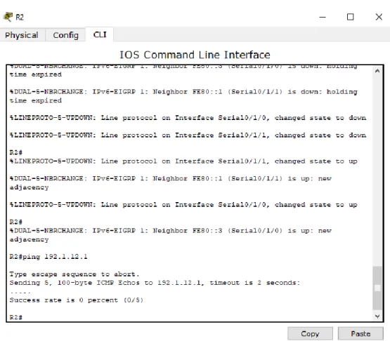
Ilustración 7. Relación BGP en R2
Codificación de los ID para los routers BGP:
R1#conf t
Enter configuration commands, one per line. End with CNTL/Z. R1(config)#router bgp 100
R1(config-router)#bgp router-id 11.11.11.11 25
R1(config-router)#%BGP-5-ADJCHANGE: neighbor 192.1.12.2 Up R2#conf t
R2(config-router)#bgp router-id 22.22.22.22 R2(config-router)#
%BGP-5-ADJCHANGE: neighbor 192.1.12.1 Up
2. Configure una relación de vecino BGP entre R2 y R3. R2 ya debería estar configurado en AS2 y R3 debería estar en AS3. Anuncie las direcciones de Loopback de R3 en BGP. Codifique el ID del router R3 como 33.33.33.33. Presente el paso a con los comandos utilizados y la salida del comando show ip route.
R2
R2#conf t
Enter configuration commands, one per line. End with CNTL/Z. R2(config)#router bgp 200
R2(config-router)#network 192.1.12.2 mask 255.255.255.0 R2(config-router)#neighbor 192.1.12.3 remote-as 300 R2(config-router)#
R3
R3#conf t
Enter configuration commands, one per line. End with CNTL/Z. R3(config)#router bgp 300
R3(config-router)#network 192.1.12.3 mask 255.255.255.0 R3(config-router)#neighbor 192.1.12.2 remote-as 200 R3(config-router)#
29 R3#conf t
Enter configuration commands, one per line. End with CNTL/Z. R3(config)#router bgp 300
R3(config-router)#bgp router-id 33.33.33.33 R3(config-router)#exit
R3(config)#end R3#
%SYS-5-CONFIG_I: Configured from console by console R3#show ip bgp
BGP table version is 1, local router ID is 33.33.33.33
3. Configure una relación de vecino BGP entre R3 y R4. R3 ya debería estar configurado en AS3 y R4 debería estar en AS4. Anuncie las direcciones Loopback de R4 en BGP. Codifique el ID del router R4 como 44.44.44.44. Establezca las relaciones de vecino con base en las direcciones de Loopback 0. Cree rutas estáticas para alcanzar la Loopback 0 del otro router. No anuncie la Loopback 0 en BGP. Anuncie la red Loopback de R4 en BGP. Presente el paso como los comandos utilizados y salida del comando show ip route
R3: R3#conf t
Enter configuration commands, one per line. End with CNTL/Z. R3(config)#router bgp 300
R3(config-router)#network 3.3.3.3 mask 255.0.0.0 R3(config-router)#neighbor 4.4.4.4 remote-as 400 R3(config-router)#exit
R3(config)#end R3#
R4
R4#conf t
Enter configuration commands, one per line. End with CNTL/Z. R4(config)#router bgp 400
R4(config-router)#network 4.4.4.4 mask 255.0.0.0 R4(config-router)#neighbor 3.3.3.3 remote-as 300 R4(config-router)#exit
R4(config)#end R4#
%SYS-5-CONFIG_I: Configured from console by console
Se codifica el ID para el router R4:
R4#conf t
Enter configuration commands, one per line. End with CNTL/Z. R4(config)#router bgp 400 28
R4(config-router)#bgp router-id 44.44.44.44 R4(config-router)#exit
31
Ilustración 9. Creación de la ruta estática R3
33
Ilustración 11. Funcionamiento de conexión establecida en R3
ESCENARIO 3
Ilustración 13. Escenario 3
SWT1 Switch>en Switch#conf t
Enter configuration commands, one per line. End with CNTL/Z. Switch(config)#VTP domain CCNP
Changing VTP domain name from NULL to CCNP Switch(config)#vtp mode client
35
Setting device VLAN database password to cisco
SWT2: Switch>en Switch#conf t
Enter configuration commands, one per line. End with CNTL/Z. Switch(config)#hostname SWT2
SWT2(config)#end SWT2#
%SYS-5-CONFIG_I: Configured from console by console SWT2#conf t
Enter configuration commands, one per line. End with CNTL/Z. SWT2(config)#vtp mode server
Device mode already VTP SERVER. SWT2(config)#vtp domain CCNP Domain name already set to CCNP. SWT2(config)#vtp password cisco
Setting device VLAN database password to cisco SWT2(config)#
SWT3:
Switch>en Switch#conf
SWT3(config)#end SWT3#
%SYS-5-CONFIG_I: Configured from console by console SWT3#conf t
Enter configuration commands, one per line. End with CNTL/Z. SWT3(config)#VTP domain CCNP
Changing VTP domain name from NULL to CCNP SWT3(config)#vtp mode client
Setting device to VTP CLIENT mode. SWT3(config)#vtp password cisco
Setting device VLAN database password to cisco SWT3(config)#
B. Configurar DTP (Dynamic Trunking Protocol)
1. Configure un enlace troncal (“trunk”) dinámico entre SWT1 y SWT2. Debido a que el modo por defecto es dynamic auto, solo un lado del enlace debe
configurarse como dynamic desirable
SWT1:
SWT1>en SWT1#conf t
Enter configuration commands, one per line. End with CNTL/Z. SWT1(config)#int fa0/1
SWT1(config-if)#switchport mode dynamic desirable SWT1
37 SWT1(config-if)#exit
SWT1(config)#end SWT1#
%SYS-5-CONFIG_I: Configured from console by console
2. Verifique el enlace “trunk” entre SWT1 y SWT2 usando el comando show interfaces trunk.
Ilustración 14. Comando show interfaces trunk SWT1
3. Entre SWT1 y SWT3 configure un enlace “trunk” estático utilizando el comando switchport mode trunk en la interfaz f0/3 de SWT1
SWT1#conf t
Enter configuration commands, one per line. End with CNTL/Z. SWT1(config)#int fa0/3
%LINEPROTO-5-UPDOWN: Line protocol on Interface FastEthernet0/3, changed state to down
%LINEPROTO-5-UPDOWN: Line protocol on Interface FastEthernet0/3, changed state to up
SWT1(config-if)#exit SWT1(config)#end SWT1#
%SYS-5-CONFIG_I: Configured from console by console
4. Verifique el enlace “trunk” con el comando show interfaces trunk en SWT1
39
5. Configure un enlace “trunk” permanente entre SWT2 y SWT3
SWT2>en SWT2#conf t
Enter configuration commands, one per line. End with CNTL/Z. SWT2(config)#int fa0/3
SWT2(config-if)#switchport mode trunk SWT2(config-if)#
%LINEPROTO-5-UPDOWN: Line protocol on Interface FastEthernet0/3, changed state to down
%LINEPROTO-5-UPDOWN: Line protocol on Interface FastEthernet0/3, changed state to up
SWT2(config-if)#exit SWT2(config)#end SWT2#
%SYS-5-CONFIG_I: Configured from console by console
C. Agregar VLANs y asignar puertos 1. En SWT1 agregue la VLAN 10. En SWT2 agregue las VLANS Compras (10), Mercadeo (20), Planta (30) y Admon (99)
SWT2: SWT2>en SWT2#conf t
Enter configuration commands, one per line. End with CNTL/Z. SWT2(config)#vlan 10
SWT2(config-vlan)#name VLAN_Compras SWT2(config-vlan)#exit
SWT2(config)#vlan 20
SWT2(config-vlan)#name VLAN_Mercadeo SWT2(config-vlan)#exit
SWT2(config)#vlan 30
SWT2(config-vlan)#name VLAN_Planta SWT2(config-vlan)#exit
SWT2(config)#vlan 99
SWT2(config-vlan)#name VLAN_Admon SWT2(config-vlan)#exit
SWT2(config)#end SWT2#
41 SWT1:
SWT1#conf t
Enter configuration commands, one per line. End with CNTL/Z. SWT1(config)#int fa0/10
SWT1(config-if)#sw access vlan 10 SWT1(config-if)#exit
SWT1(config)#end SWT1#
%SYS-5-CONFIG_I: Configured from console by console
3. Verifique que las VLANs han sido agregadas correctamente.
4. Asocie los puertos a las VLAN y configure las direcciones IP de acuerdo con la siguiente tabla.
Tabla 2. Direcciones IP
SWT1:
SWT1#conf t
Enter configuration commands, one per line. End with CNTL/Z.
SWT1(config)#int fa0/10
SWT1(config-if)#switchport mode Access
SWT1(config-if)#switchport access vlan 10
SWT1(config-if)#exit SWT1(config)#int fa0/15 SWT1(config-if)# exit SWT1#
%SYS-5-CONFIG_I: Configured from console by console
SWT1#conf t
Enter configuration commands, one per line. End with CNTL/Z.
SWT1(config)#int fa0/15
SWT1(config-if)#switchport mode access SWT1(config-if)#switchport access vlan 20 SWT1(config-if)#exit
SWT1(config)#int fa0/20
43 SWT1(config-if)#exit
SWT1(config)#end SWT1#
%SYS-5-CONFIG_I: Configured from console by console
Ilustración 19. IP configuration PC4
45 SWT3
SWT3>en SWT3#conf t
Enter configuration commands, one per line. End with CNTL/Z. SWT3(config)#int fa0/10
SWT3(config-if)#switchport mode access SWT3(config-if)#switchport access vlan 10 SWT3(config-if)#exit
SWT3(config)#int fa0/15
SWT3(config-if)#switchport mode access SWT3(config-if)#switchport access vlan 20 SWT3(config-if)#exit
SWT3(config)#int fa0/20
SWT3(config-if)#switchport mode access SWT3(config-if)#switchport access vlan 30 SWT3(config-if)#exit
SWT3(config)#end SWT3#
Ilustración 21. IP configuration PC 6
47
Ilustración 23. IP configuration PC8
4. Configure el puerto F0/10 en modo de acceso para SWT1, SWT2 y SWT3 y asígnelo a la VLAN 10
5. Repita el procedimiento para los puertos F0/15 y F0/20 en SWT1, SWT2 y SWT3. Asigne las VLANs y las direcciones IP de los PCs de acuerdo con la tabla de arriba.
D. Configurar las direcciones IP en los switches
Tabla 3. Direccionamiento de Switches
SWT1:
SWT1>en SWT1#conf t
Enter configuration commands, one per line. End with CNTL/Z. SWT1(config)#int vlan 99
SWT1(config-if)#
%LINK-5-CHANGED: Interface Vlan99, changed state to up
%LINEPROTO-5-UPDOWN: Line protocol on Interface Vlan99, changed state to up
SWT1(config-if)#ip address 190.108.99.1 255.255.255.0 SWT1(config-if)#no shutdown
SWT1(config-if)#exit SWT1(config)#end SWT1#
%SYS-5-CONFIG_I: Configured from console by console
SWT2: SWT2>en SWT2#conf t
49 SWT2(config)#int vlan 99
SWT2(config-if)#
%LINK-5-CHANGED: Interface Vlan99, changed state to up
%LINEPROTO-5-UPDOWN: Line protocol on Interface Vlan99, changed state to up
SWT2(config-if)#ip address 190.108.99.2 255.255.255.0 SWT2(config-if)#no shutdown
SWT2(config-if)#exit SWT2(config)#end SWT2#
%SYS-5-CONFIG_I: Configured from console by console
SWT3: SWT3>en SWT3#conf t
Enter configuration commands, one per line. End with CNTL/Z. SWT3(config)#int vlan 99
SWT3(config-if)#
%LINK-5-CHANGED: Interface Vlan99, changed state to up
%LINEPROTO-5-UPDOWN: Line protocol on Interface Vlan99, changed state to up
SWT3(config-if)#ip address 190.108.99.3 255.255.255.0 SWT3(config-if)#no shutdown
SWT3(config-if)#exit SWT3(config)#end
E. Verificar la conectividad Extremo a Extremo
1. Ejecute un Ping desde cada PC a los demás. Explique por qué el ping tuvo o no tuvo éxito.
Ilustración 24. Ping PC1
5. Ejecute un Píng desde cada Switch a cada PC.
51
CONCLUSIONES
Se desarrolla la guía de actividades necesaria para optar por el título de Ingeniero Electrónico.
Se desarrollaron los tres escenarios que abarcan los temas de Switches y Routers.
La simulación en Packet Tracer es muy importante para verificar el funcionamiento de la teoría que hemos aprendido.
BIBLIOGRAFÍA
UNAD (2015). Introducción a la configuración de Switches y Routers [OVA]. Recuperado de https://1drv.ms/u/s!AmIJYei-NT1IhgL9QChD1m9EuGqC
Temática: First Hop Redundancy Protocols
Froom, R., Frahim, E. (2015). CISCO Press (Ed). First Hop Redundancy Protocols. Implementing Cisco IP Switched Networks (SWITCH) Foundation Learning Guide CCNP SWITCH 300-115. Recuperado de
https://1drv.ms/b/s!AmIJYei-NT1IlnWR0hoMxgBNv1CJ
Temática: Network Management
Froom, R., Frahim, E. (2015). CISCO Press (Ed). Network Management.
Implementing Cisco IP Switched Networks (SWITCH) Foundation Learning Guide CCNP SWITCH 300-115. Recuperado de