1
EVALUACIÓN FINAL
PRUEBA DE HABILIDADES PRÁCTICAS CISCO CCNP
JONH STEVEN POSSO CAICEDO
UNIVERSIDAD NACIONAL ABIERTA Y A DISTANCIA - UNAD
FACULTA DE CIENCIAS BASICAS, TECNOLOGÍA E INGENIERÍA - ECBTI INGENIERIA ELECTRONICA
2
EVALUACIÓN PRUEBA DE HABILIDADES PRACTICAS CCNP
JONH STEVEN POSSO CAICEDO
Diplomado de opción de grado presentado para optar el título de INGENIERO ELECTRONICO
Director:
Giovanni Alberto Bracho
Magíster en Ingeniería De Sistemas y Computación
UNIVERSIDAD NACIONAL ABIERTA Y A DISTANCIA - UNAD FACULTA DE CIENCIAS BASICAS, TECNOLOGÍA E INGENIERÍA- ECBTI
INGENIERIA ELECTRONICA PITALITO - HUILA
3
NOTA DE ACEPTACIÓN:
Presidente del Jurado
Jurado
Jurado
Pitalito Huila, 17 de marzo de 2020
4
AGRADECIMIENTOS
En este proceso de formación académico que se da por finalizado, primero que todo doy gracias a Dios por haberme dado la oportunidad de guiar mi camino en esta prestigiosa universidad como lo es la Universidad Nacional Abierta y a Distancia, la cual me ayudo en mi proceso de formación académico y profesional para afrontar mis futuros proyectos en el ámbito profesional y personal.
5
TABLA DE CONTENIDO
LISTA DE ILUSTRACIONES……….6
LISTA DE TABLAS ……….7
GLOSARIO ……….8
RESUMEN……….9
ABSTRACT………...………...9
INTRODUCCIÓN………...10
1. EVALUACIÓN PRUEBA DE HABILIDADES PRACTICAS CCNP …...………11
1.1. ESCENARIO 1………...……….11
1.1.1. Parte 1: Configuración del escenario propuesto………12
1.1.2. Parte 2: Verificar conectividad de red y control de la trayectoria…...18
1.2. ESCENARIO 2………...23
1.2.1. Parte 1: Configurar la red de acuerdo con las especificaciones……24
1.2.2. Parte 2: conectividad de red de prueba y las opciones configuradas………..…….36
CONCLUSIONES………..40
6
LISTA DE ILUSTRACIONES
Ilustración 1. Escenario 1 ... 11
Ilustración 2. Escenario 1, Desarrollado en Packet Tracer ... 11
Ilustración 3. CALI (R1), tabla de enrutamiento en Packet Tracer ... 18
Ilustración 4. OCAÑA (R2), tabla de enrutamiento en Packet Tracer ... 19
Ilustración 5. BARRANQUILLA (R3), tabla de enrutamiento en Packet Tracer ... 20
Ilustración 6. CALI (R1), ping de R1 a R2 en Packet Tracer ... 20
Ilustración 7. OCAÑA (R2), ping de R2 a R1 en Packet Tracer ... 21
Ilustración 8. OCAÑA (R2), ping de R2 a R3 en Packet Tracer ... 21
Ilustración 9. BARRANQUILLA (R3), ping de R3 a R2 en Packet Tracer ... 21
Ilustración 10. BARRANQUILLA (R3), ping de R3 a R1 en Packet Tracer ... 22
Ilustración 11. Escenario 2 ... 23
Ilustración 12. Escenario 2, Desarrollado en Packet Tracer ... 23
Ilustración 13. DLS1, configuración de Vlan en Packet Tracer ... 36
Ilustración 14. DLS1, configuración de Vtp en Packet Tracer ... 36
Ilustración 15. DLS1, configuración de Interface en Packet Tracer ... 37
Ilustración 16. DLS2, configuración de Vlan en Packet Tracer ... 37
Ilustración 17. DLS2, configuración de Vtp en Packet Tracer ... 38
Ilustración 18. DLS2, configuración de Interface en Packet Tracer ... 38
Ilustración 19. DLS1, Verificación de EtherChannel en Packet Tracer ... 39
7
LISTA DE TABLAS
8 GLOSARIO
CCNP: (Cisco Certified Network Professional) es el nivel intermedio de certificación de la compañía. Para obtener esta certificación, se han de superar varios exámenes, clasificados según la empresa en 3 módulos.
Gns3: Es un simulador gráfico de red lanzado en 2008, que te permite diseñar topologías de red complejas y poner en marcha simulaciones sobre ellos,123 permitiendo la combinación de dispositivos tanto reales como virtuales.
Networking: aplica a las redes de cómputo para vincular dos o más dispositivos informáticos con el propósito de compartir datos. Las redes están construidas con una mezcla de hardware y software, incluyendo el cableado necesario para conectar los equipos.
Una red o red de datos es una red de telecomunicaciones que permite a los equipos de cómputo intercambiar datos.
Protocolos de red: designa el conjunto de reglas que rigen el intercambio de información a través de una red de computadoras. Este protocolo funciona de la siguiente forma, cuando se transfiere información de un ordenador a otro, por ejemplo, mensajes de correo electrónico o cualquier otro tipo de datos esta no es transmitida de una sola vez, sino que se divide en pequeñas partes.
9 RESUMEN
En el siguiente trabajo, desarrollaremos dos (2) escenarios, el primero de Router y el segundo de Switch, que nos permitirá poner en práctica lo que hemos aprendido durante el diplomado, configurando cada uno de los dispositivos y escribiendo el paso a paso de todas las etapas realizadas y la verificación de conectividad de los escenarios mediante comandos como: ping, Show Vlan, Show ip Int brief, show vtp status, show ip protocols, Show ip eigr topology.
Además, realizaremos la configuración de los escenarios usando la herramienta de simulación Pakect tracer que permiten establecer un análisis sobre el comportamiento de los diferentes protocolos y evaluar su funcionamiento.
Palabras clave: Switch, Router, Pakect tracer, protocolos.
ABSTRACT
In the following work, we will develop two (2) scenarios, the first for the Router and the second for the Switch, which will allow us to put into practice what we have learned during the diploma course, configuring each of the devices and writing the step-by-step of all the stages carried out and the Connectivity verification of the scenarios using commands such as: ping, Show Vlan, Show ip Int brief, show vtp status, show ip protocols, Show ip eigr topology.
In addition, we will configure the scenarios using the Pakect tracer simulation tool that allow us to establish an analysis of the behavior of the different protocols and evaluate their operation.
10
INTRODUCCIÓN
En la actualidad las redes informáticas están presentes casi en todos los ámbitos cotidianos, cuando utilizamos nuestra computadora o nuestro celular para intercambiar información, estamos utilizando una red de telecomunicaciones que no lo permite; en el mundo las industrias, empresas, universidades, gobiernos utilizan diferentes implementaciones de redes para sus procesos de desarrollo con el fin de mejorar sus producciones, un buen traslado de información permite la eficiencia de aquí la importancia de conocer su funcionamiento.
Las redes informáticas no son distintas en su lógica de intercambio de los demás procesos de comunicación conocidos: cuentan con un emisor, un receptor y un mensaje, así como un medio a través del cual transmitirlo y una serie de códigos o protocolos para garantizar su comprensión.
11
1. EVALUACIÓN PRUEBA DE HABILIDADES PRACTICAS CCNP
1.1. ESCENARIO 1
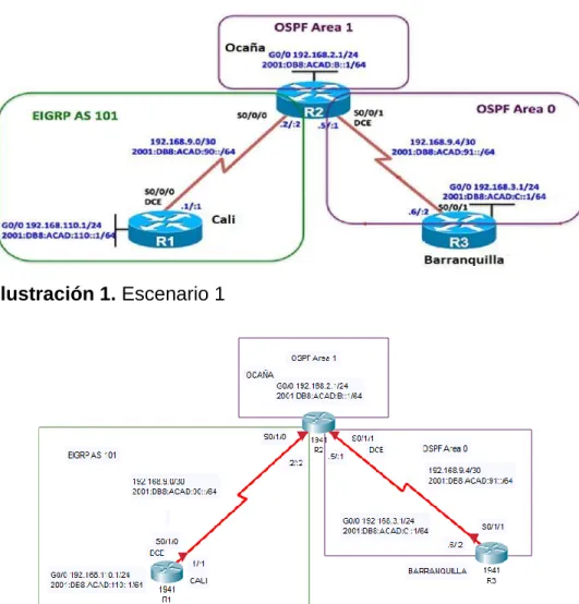
Una empresa de confecciones posee tres sucursales distribuidas en las ciudades de Cali, Barranquilla y Ocaña, en donde el estudiante será el administrador de la red, el cual deberá configurar e interconectar entre sí cada uno de los dispositivos que forman parte del escenario, acorde con los lineamientos establecidos para el direccionamiento IP, protocolos de enrutamiento y demás aspectos que forman parte de la topología de red.
Topología de red
Ilustración 1. Escenario 1
12
1.1.1. Parte 1: Configuración del escenario propuesto
1. Configurar las interfaces con las direcciones IPv4 e IPv6 que se muestran en la topología de red.
Configuración de las interfaces del Router CALI (R1)
Router>enable Router>config t
Router(config)# hostname CALI CALI (config)# interface Serial0/1/0
CALI (config-if)# ip address 192.168.9.1 255.255.255.252 CALI (config-if)# ipv6 address FE80::1 link -local
CALI (config-if)# ipv6 address 2001:DB8:ACAD:90::1/64 CALI (config-if)# clock rate 64000
CALI (config-if) # no shut CALI (config-if)# exit
CALI (config)# interface GigabitEthernet0/0
CALI (config-if)# ip address 192.168.110.1 255.255.255.0 CALI (config-if)# ipv6 address FE80::1 link -local
CALI (config-if)# ipv6 address 2001:DB8:ACAD:110::1/64 CALI (config-if)# no shut
CALI (config-if)# exit
Configuración de las interfaces del Router OCAÑA (R2)
Router>enable Router>config t
Router(config)# hostname OCAÑA OCAÑA (config)# interface s0/1/0
OCAÑA (config-if)# ip address 192.168.9.2 255.255.255.252 OCAÑA (config-if)# ipv6 address FE80::2 link-local
OCAÑA (config-if)# ipv6 address 2001:DB8:ACAD:90::2/64 OCAÑA (config-if)# no shut
OCAÑA (config-if)# Exit
OCAÑA (config)# interface g0/0
OCAÑA (config-if)# ip address 192.168.2.1 255.255.255.0 OCAÑA (config-if)# ipv6 address FE80::2 link-local
13 OCAÑA (config-if)# no shut
OCAÑA (config-if)# Exit
OCAÑA (config)# interface s0/1/1
OCAÑA (config-if)# ip address 192.168.9.5 255.255.255.252 OCAÑA (config-if)# ipv6 address FE80::2 link-local
OCAÑA (config-if)# ipv6 address 2001:DB8:ACAD:91::1/64 OCAÑA (config-if)# clock rate 64000
OCAÑA (config-if)# no shut OCAÑA (config-if)# Exit
Configuración de las interfaces del Router BARRANQUILLA (R3)
Router>enable Router>config t
Router(config)# hostname BARRANQUILLA BARRANQUILLA (config)# interface s0/1/1
BARRANQUILLA (config-if)# ip address 192.168.9.6 255.255.255.252 BARRANQUILLA (config-if)# ipv6 address FE80::3 link-local
BARRANQUILLA (config-if)# ipv6 address 2001:DB8:ACAD:91::2/64 BARRANQUILLA (config-if)# no shut
BARRANQUILLA (config-if)# Exit
BARRANQUILLA (config)# interface g0/0
BARRANQUILLA (config-if)# ip address 192.168.3.1 255.255.255.0 BARRANQUILLA (config-if)# ipv6 address FE80::3 link-local
BARRANQUILLA (config-if)# ipv6 address 2001:DB8:ACAD:C::1/64 BARRANQUILLA (config-if)# no shut
BARRANQUILLA (config-if)# Exit
2. Ajustar el ancho de banda a 128 kbps sobre cada uno de los enlaces seriales ubicados en R1, R2, y R3 y ajustar la velocidad de reloj de las conexiones de DCE según sea apropiado.
Configuración del ancho de banda CALI (R1)
14
Configuración del ancho de banda OCAÑA (R2)
OCAÑA (config)# interface s0/1/0 OCAÑA (config-if)# bandwidth 128 OCAÑA (config-if)# Exit
OCAÑA (config)# interface s0/1/1 OCAÑA (config-if)# bandwidth 128 OCAÑA (config-if)# Exit
Configuración del ancho de banda BARRANQUILLA (R3)
BARRANQUILLA (config)# interface s0/1/1 BARRANQUILLA (config-if)# bandwidth 128 BARRANQUILLA (config-if)# Exit
3. En R2 y R3 configurar las familias de direcciones OSPFv3 para IPv4 e IPv6. Utilice el identificador de enrutamiento 2.2.2.2 en R2 y 3.3.3.3 en R3 para ambas familias de direcciones.
Configuración de la ruta del Router OCAÑA (R2)
OCAÑA (config)# ipv6 unicast-routing OCAÑA (config)# router ospf 1
OCAÑA (config-router)# router-id 2.2.2.2 OCAÑA (config-router)#exit
Configuración de la ruta del Router OCAÑA (R2)
BARRANQUILLA (config)# ipv6 unicast-routing BARRANQUILLA (config)# router ospf 1
15
4. En R2, configurar la interfaz F0/0 en el área 1 de OSPF y la conexión serial entre R2 y R3 en OSPF área 0.
OCAÑA (config)# router ospf 1
OCAÑA (config-router)# network 192.168.2.0 0.0.0.255 area 1 OCAÑA (config-router)# network 192.168.9.4 0.0.0.3 area 0 OCAÑA (config-router)# ipv6 unicast-routing
OCAÑA (config)#int g0/0
OCAÑA (config-if)# ipv6 ospf 1 area 1 OCAÑA (config-if)# no shut
OCAÑA (config-if)#exit
OCAÑA (config)# interface serial 0/1/1 OCAÑA (config-if)# ipv6 ospf 1 area 0 OCAÑA (config-if)# no shut
OCAÑA (config-if)#exit
5. En R3, configurar la interfaz F0/0 y la conexión serial entre R2 y R3 en OSPF área 0.
BARRANQUILLA (config)# router ospf 1
BARRANQUILLA (config-router)# network 192.168.3.0 0.0.0.255 area 0 BARRANQUILLA (config-router)# network 192.168.9.4 0.0.0.3 area 0 BARRANQUILLA (config-router)# ipv6 unicast-routing
BARRANQUILLA (config)#int g0/0
BARRANQUILLA (config-if)# ipv6 ospf 1 area 0 BARRANQUILLA (config-if)# no shut
BARRANQUILLA (config-if)#exit
BARRANQUILLA (config)# interface serial 0/1/1 BARRANQUILLA (config-if)# ipv6 ospf 1 area 0 BARRANQUILLA (config-if)# no shut
BARRANQUILLA (config-if)#exit
6. Configurar el área 1 como un área totalmente Stubby.
16
7. Propagar rutas por defecto de IPv4 y IPv6 en R3 al interior del dominio OSPFv3.
Nota: Es importante tener en cuenta que una ruta por defecto es diferente a la definición de rutas estáticas.
BARRANQUILLA (config)# ipv6 route ::/0 2001:DB8:ACAD:91:: BARRANQUILLA (config)#ipv6 router ospf 1
BARRANQUILLA (config-rtr)# default-information originate BARRANQUILLA (config-rtr)# exit
8. Realizar la configuración del protocolo EIGRP para IPv4 como IPv6. Configurar la interfaz F0/0 de R1 y la conexión entre R1 y R2 para EIGRP con el sistema autónomo 101. Asegúrese de que el resumen automático está desactivado.
Configuración de EIGRP en el Router CALI (R1)
CALI (config)# router eigrp 101
CALI (config-router)# network 192.168.110.0 CALI (config-router)# network 192.168.9.0 CALI (config-router)# no auto-summary CALI (config-router)#exit
Configuración de EIGRP en el Router OCAÑA (R2)
OCAÑA (config)# router eigrp 101
OCAÑA (config-router)# network 192.168.2.0 OCAÑA (config-router)# network 192.168.9.0 OCAÑA (config-router)# no auto-summary OCAÑA (config-router)#exit
9. Configurar las interfaces pasivas para EIGRP según sea apropiado.
CALI (config)# router eigrp 101
17 CALI (config-router)# passive-interface g0/0 CALI (config-router)# exit
10. En R2, configurar la redistribución mutua entre OSPF y EIGRP para IPv4 e IPv6. Asignar métricas apropiadas cuando sea necesario.
OCAÑA (config)# router ospf 1
OCAÑA (config-router)# redistribute eigrp 101 subnets OCAÑA (config-router)# exit
OCAÑA (config)# router eigrp 101
OCAÑA (config-router)# redistribute ospf 1 metric 10000 100 255 1 1500 OCAÑA (config-router)# exit
11. En R2, de hacer publicidad de la ruta 192.168.3.0/24 a R1 mediante una lista de distribución y ACL.
18
1.1.2. Parte 2: Verificar conectividad de red y control de la trayectoria.
a. Registrar las tablas de enrutamiento en cada uno de los routers, acorde con los parámetros de configuración establecidos en el escenario propuesto.
19
20
Ilustración 5. BARRANQUILLA (R3), tabla de enrutamiento en Packet Tracer.
b. Verificar comunicación entre routers mediante el comando ping y traceroute
21
Ilustración 7. OCAÑA (R2), ping de R2 a R1 en Packet Tracer.
Ilustración 8. OCAÑA (R2), ping de R2 a R3 en Packet Tracer.
22
Ilustración 10. BARRANQUILLA (R3), ping de R3 a R1 en Packet Tracer.
c. Verificar que las rutas filtradas no están presentes en las tablas de enrutamiento de los routers correctas.
23 1.2. Escenario 2
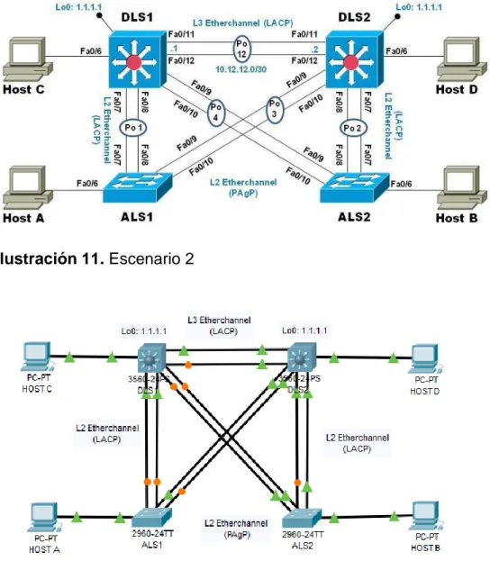
Una empresa de comunicaciones presenta una estructura Core acorde a la topología de red, en donde el estudiante será el administrador de la red, el cual deberá configurar e interconectar entre sí cada uno de los dispositivos que forman parte del escenario, acorde con los lineamientos establecidos para el direccionamiento IP, etherchannels, VLANs y demás aspectos que forman parte del escenario propuesto.
Topología de red
Ilustración 11. Escenario 2
24
1.2.1. Parte 1: Configurar la red de acuerdo con las especificaciones.
a) Apagar todas las interfaces en cada switch.
b) Asignar un nombre a cada switch acorde al escenario establecido.
Configuración del Switch DLS1
Switch>enable Switch# config t
Switch (config)# hostname DLS1
DLS1 (config)# interface range fastEthernet 0/6 – 12 DLS1 (config-if-range)# shutdown
DLS1 (config-if-range)# exit
Configuración del Switch DLS2
Switch>enable Switch# config t
Switch (config)# hostname DLS2
DLS1 (config)# interface range fastEthernet 0/6 – 12 DLS1 (config-if-range)# shutdown
DLS1 (config-if-range)# exit
Configuración del Switch ALS1
Switch>enable Switch# config t
Switch (config)# hostname ALS1
ALS1 (config)# interface range fastEthernet 0/6 – 12 ALS1 (config-if-range)# shutdown
ALS1 (config-if-range)# exit
25 Switch>enable
Switch# config t
Switch (config)# hostname ALS2
ALS2 (config)# interface range fastEthernet 0/6 – 12 ALS2 (config-if-range)# shutdown
ALS2 (config-if-range)# exit
c) Configurar los puertos troncales y Port-channels tal como se muestra en el diagrama.
1. La conexión entre DLS1 y DLS2 será un EtherChannel capa-3 utilizando LACP. Para DLS1 se utilizará la dirección IP 10.12.12.1/30 y para DLS2 utilizará 10.12.12.2/30.
Configuración del Switch DLS1
DLS1(config)# int vlan 800
DLS1(config-if)# ip address 10.12.12.1 255.255.255.252 DLS1(config)# interface range f0/11 - 12
DLS1(config-if-range)# channel-protocol lacp
DLS1(config-if-range)# channel-group 3 mode active DLS1(config-if-range)# no shut
DLS1(config-if-range)# exit
Configuración del Switch DLS2
DLS2(config)# int vlan 800
DLS2(config-if)# ip address 10.12.12.2 255.255.255.252 DLS2(config)# interface range f0/11 - 12
DLS2(config-if-range)# channel-protocol lacp
DLS2(config-if-range)# channel-group 3 mode active DLS2(config-if-range)# no shut
26
2. Los Port-channels en las interfaces Fa0/7 y Fa0/8 utilizarán LACP.
Configuración del Switch DLS1
DLS1(config)# interface range f0/7 - 8
DLS1(config-if-range)# channel-protocol lacp
DLS1(config-if-range)# channel-group 2 mode active DLS1(config-if-range)# no shut
DLS1(config-if-range)# exit
Configuración del Switch DLS2
DLS2(config)# interface range f0/7 - 8
DLS2(config-if-range)# channel-protocol lacp
DLS2(config-if-range)# channel-group 2 mode active DLS2(config-if-range)# no shut
DLS2(config-if-range)# exit
Configuración del Switch ALS1
ALS1(config)# interface range f0/7 - 8
ALS1(config-if-range)# channel-protocol lacp
ALS1(config-if-range)# channel-group 2 mode active ALS1(config-if-range)# no shut
ALS1(config-if-range)# exit
Configuración del Switch ALS2
ALS2(config)# interface range f0/7 - 8
ALS2(config-if-range)# channel-protocol lacp
ALS2(config-if-range)# channel-group 2 mode active ALS2(config-if-range)# no shut
27
3. Los Port-channels en las interfaces F0/9 y fa0/10 utilizará PAgP.
Configuración del Switch DLS1
DLS1(config)# interface range f0/9 - 10
DLS1(config-if-range)# channel-protocol pagp
DLS1(config-if-range)# channel-group 1 mode desirable DLS1(config-if-range)# no shut
DLS1(config-if-range)# exit
Configuración del Switch DLS2
DLS2(config)# interface range f0/9 - 10
DLS2(config-if-range)# channel-protocol pagp
DLS2(config-if-range)# channel-group 1 mode desirable DLS2(config-if-range)# no shut
DLS2(config-if-range)# exit
Configuración del Switch ALS1
ALS1(config)# interface range f0/9 - 10
ALS1(config-if-range)# channel-protocol pagp
ALS1(config-if-range)# channel-group 1 mode desirable ALS1(config-if-range)# no shut
ALS1(config-if-range)# exit
Configuración del Switch ALS2
ALS2(config)# interface range f0/9 - 10
ALS2(config-if-range)# channel-protocol pagp
ALS2(config-if-range)# channel-group 1 mode desirable ALS2(config-if-range)# no shut
28
4. Todos los puertos troncales serán asignados a la VLAN 800 como la VLAN nativa.
Configuración del Switch DLS1
DLS1(config)# interface range f0/7 – 12
DLS1(config-if-range)# switchport trunk encap dot1q DLS1(config-if-range)# switchport trunk native vlan 800 DLS1(config-if-range)# switchport mode trunk
DLS1(config-if-range)# switchport nonegotiate DLS1(config-if-range)# no shut
Configuración del Switch DLS2
DLS2(config)# interface range f0/7 – 12
DLS2(config-if-range)# switchport trunk encap dot1q DLS2(config-if-range)# switchport trunk native vlan 800 DLS2(config-if-range)# switchport mode trunk
DLS2(config-if-range)# switchport nonegotiate DLS2(config-if-range)# no shut
Configuración del Switch ALS1
ALS1(config)# interface range f0/7 – 12
ALS1(config-if-range)# switchport trunk native vlan 800 ALS1(config-if-range)# switchport mode trunk
ALS1(config-if-range)# switchport nonegotiate ALS1(config-if-range)# no shut
Configuración del Switch ALS2
ALS2(config)# interface range f0/7 – 12
ALS2(config-if-range)# switchport trunk native vlan 800 ALS2(config-if-range)# switchport mode trunk
29
d) Configurar DLS1, ALS1, y ALS2 para utilizar VTP versión 3
1. Utilizar el nombre de dominio UNAD con la contraseña cisco123
Configuración del Switch DLS1
DLS1 (config) #vtp mode server DLS1 (config) #vtp domain UNAD DLS1 (config) #vtp Password cisco123 DLS1 (config) #exit
Configuración del Switch ALS1
ALS1 (config) #vtp mode client ALS1 (config) #vtp domain UNAD ALS1 (config) #vtp Password cisco123
Configuración del Switch ALS2
ALS2 (config) #vtp mode client ALS2 (config) #vtp domain UNAD ALS2 (config) #vtp Password cisco123 ALS2 (config) #exit
2. Configurar DLS1 como servidor principal para las VLAN.
DLS1#conf t
DLS1 (config) #vtp version 2
3. Configurar ALS1 y ALS2 como clientes VTP.
30
e) Configurar en el servidor principal las siguientes VLAN:
Número de VLAN Nombre de VLAN Número de VLAN Nombre de VLAN
800 NATIVA 434 ESTACIONAMIENTO
12 EJECUTIVOS 123 MANTENIMIENTO
234 HUESPEDES 101 VOZ
111 VIDEONET 345 ADMINISTRACIÓN
Tabla 1. VLAN
DLS1#conf t
DLS1 (config) #vlan 800
DLS1 (config-vlan) #name NATIVA DLS1 (config-vlan) #exit
DLS1 (config) #vlan 12
DLS1 (config-vlan) #name EJECUTIVOS DLS1 (config-vlan) #exit
DLS1 (config) #vlan 234
DLS1 (config-vlan) #name HUESPEDES DLS1 (config-vlan) #exit
DLS1 (config) #vlan 111
DLS1 (config-vlan) #name VIDEONET DLS1 (config-vlan) #exit
DLS1 (config) #vlan 434
DLS1 (config-vlan) #name ESTACIONAMIENTO DLS1 (config-vlan) #exit
DLS1 (config) #vlan 123
DLS1 (config-vlan) #name MANTENIMIENTO DLS1 (config-vlan) #exit
DLS1 (config) #vlan 101
DLS1 (config-vlan) #name VOZ DLS1 (config-vlan) #exit
DLS1 (config) #vlan 345
31 f) En DLS1, suspender la VLAN 434.
DLS1 (config) #vlan 434
DLS1 (config-vlan) # State suspend DLS1 (config-vlan) #exit
Nota: Packet tracer no reconoce este comando.
g) Configurar DLS2 en modo VTP transparente VTP utilizando VTP versión 2, y configurar en DLS2 las mismas VLAN que en DLS1.
DLS2#conf t
DLS2 (config) # vtp version 2
DLS2 (config) # vtp mode transparent DLS2 (config) #vlan 800
DLS2 (config-vlan) #name NATIVA DLS2 (config-vlan) #exit
DLS2 (config) #vlan 12
DLS2 (config-vlan) #name EJECUTIVOS DLS2 (config-vlan) #exit
DLS2 (config) #vlan 234
DLS2 (config-vlan) #name HUESPEDES DLS2 (config-vlan) #exit
DLS2 (config) #vlan 111
DLS2 (config-vlan) #name VIDEONET DLS2 (config-vlan) #exit
DLS2 (config) #vlan 434
DLS2 (config-vlan) #name ESTACIONAMIENTO DLS2 (config-vlan) #exit
DLS2 (config) #vlan 123
DLS2 (config-vlan) #name MANTENIMIENTO DLS2 (config-vlan) #exit
DLS2 (config) #vlan 101
DLS2 (config-vlan) #name VOZ DLS2 (config-vlan) #exit
DLS2 (config) #vlan 345
32 h) Suspender VLAN 434 en DLS2.
DLS1 (config) #vlan 434
DLS1 (config-vlan) # State suspend DLS1 (config-vlan) #exit
Nota: Packet tracer no reconoce este comando.
i) En DLS2, crear VLAN 567 con el nombre de CONTABILIDAD. La VLAN de CONTABILIDAD no podrá estar disponible en cualquier otro Switch de la red.
DLS2 (config) #vlan 567
DLS2 (config-vlan) # name CONTABILIDAD DLS2 (config-vlan) # private-vlan isolated DLS2 (config-vlan) #exit
j) Configurar DLS1 como Spanning tree root para las VLAN 1, 12, 434, 800, 101, 111 y 345 y como raíz secundaria para las VLAN 123 y 234.
DLS1#conf t
DLS1 (config) #spanning-tree vlan 1 root primary DLS1 (config) #spanning-tree vlan 12 root primary DLS1 (config) #spanning-tree vlan 434 root primary DLS1 (config) #spanning-tree vlan 800 root primary DLS1 (config) #spanning-tree vlan 101 root primary DLS1 (config) #spanning-tree vlan 111 root primary DLS1 (config) #spanning-tree vlan 345 root primary DLS1 (config) #spanning-tree vlan 123 root secondary DLS1 (config) #spanning-tree vlan 234 root secondary DLS1 (config)
k) Configurar DLS2 como Spanning tree root para las VLAN 123 y 234 y como una raíz secundaria para las VLAN 12, 434, 800, 101, 111 y 345.
33
DLS2 (config) #spanning-tree vlan 12 root secondary DLS2 (config) #spanning-tree vlan 434 root secondary DLS2 (config) #spanning-tree vlan 800 root secondary DLS2 (config) #spanning-tree vlan 101 root secondary DLS2 (config) #spanning-tree vlan 111 root secondary DLS2 (config) #spanning-tree vlan 345 root secondary
l) Configurar todos los puertos como troncales de tal forma que solamente las VLAN que se han creado se les permitirá circular a través de estos puertos.
Configuración del Switch DLS1
DLS1 (config) # int ran f0/7-12
DLS1 (config-if-range) #switchport trunk encapsulation dot1q DLS1 (config-if-range) # switchport trunk native vlan 800 DLS1 (config-if-range) #switchport mode trunk
Configuración del Switch DLS2
DLS2 (config) # int ran f0/7-12
DLS2 (config-if-range) #switchport trunk encapsulation dot1q DLS2 (config-if-range) # switchport trunk native vlan 800 DLS2 (config-if-range) #switchport mode trunk
Configuración del Switch ALS1
ALS1 (config) # int ran f0/7-12
ALS1 (config-if-range) # switchport trunk native vlan 800 ALS1 (config-if-range) # switchport mode trunk
Configuración del Switch ALS2
ALS2 (config) # int ran f0/7-12
34
m) Configurar las siguientes interfaces como puertos de acceso, asignados a las VLAN de la siguiente manera:
Interfaz DLS1 DLS2 ALS1 ALS2
Interfaz Fa0/6 345 12, 101 123, 101 234
Interfaz Fa0/15 111 111 111 111
Interfaces F0 /16-18 567
Tabla 2. Dirección IP Switches
Configuración del Switch DLS1
DLS1 (config) # interface f0/6
DLS1 (config-if) #switchport access vlan 345 DLS1 (config-if) #no sh
DLS1 (config-if) # exit
DLS1 (config) # interface f0/15
DLS1 (config-if) #switchport access vlan 111 DLS1 (config-if) #no sh
DLS1 (config-if) # exit
Configuración del Switch DLS2
DLS2 (config) # interface f0/6
DLS2 (config-if) #switchport access vlan 12 DLS2 (config-if) #switchport access vlan 101 DLS2 (config-if) #no sh
DLS2 (config-if) # exit
DLS2 (config) # interface f0/15
DLS2 (config-if) #switchport access vlan 111 DLS2 (config-if) #no sh
DLS2 (config-if) # exit
DLS2 (config) # int ran f0/16 - 18
DLS2 (config-if) #switchport access vlan 567 DLS2 (config-if) #no sh
35 Configuración del Switch ALS1
ALS1 (config) # interface f0/6
ALS1 (config-if) #switchport access vlan 123 ALS1 (config-if) #switchport access vlan 101 ALS1 (config-if) #no sh
ALS1 (config-if) # exit
ALS1 (config) # interface f0/15
ALS1 (config-if) #switchport access vlan 111 ALS1 (config-if) #no sh
ALS1 (config-if) # exit
Configuración del Switch ALS2
ALS2#conf t
ALS2 (config) # interface fastethernet 0/6 ALS2 (config-if) #switchport access vlan 234 ALS2 (config-if) #no sh
ALS2 (config-if) # exit
ALS2 (config) #interface fastethernet 0/15 ALS2 (config-if) #switchport access vlan 111 ALS2 (config-if) #no sh
36
1.2.2. Parte 2: conectividad de red de prueba y las opciones configuradas.
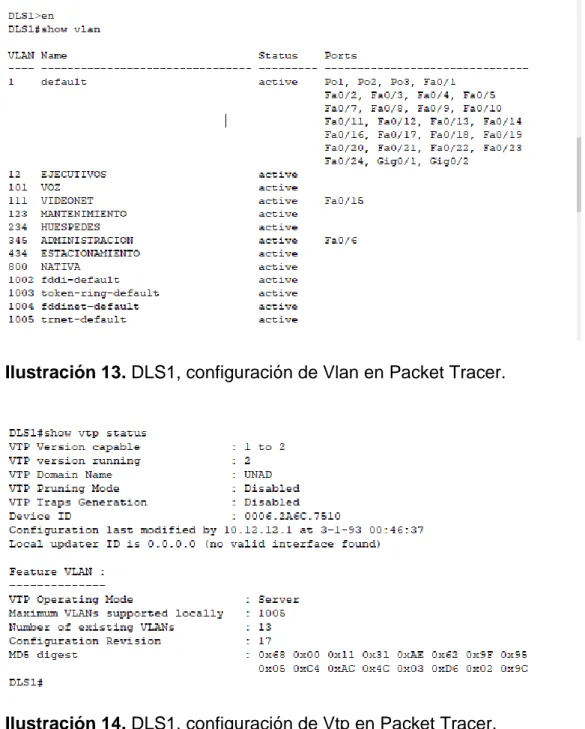
a) Verificar la existencia de las VLAN correctas en todos los switches y la asignación de puertos troncales y de acceso
Ilustración 13. DLS1, configuración de Vlan en Packet Tracer.
37
Ilustración 15. DLS1, configuración de Interface en Packet Tracer.
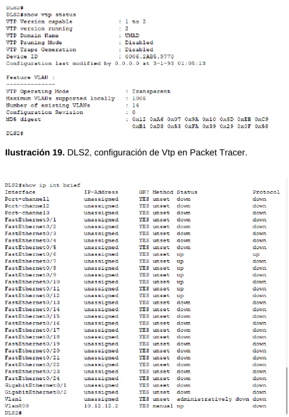
38
Ilustración 19. DLS2, configuración de Vtp en Packet Tracer.
39
b) Verificar que el EtherChannel entre DLS1 y ALS1 está configurado correctamente
Ilustración 21. DLS1, Verificación de EtherChannel en Packet Tracer.
c) Verificar la configuración de Spanning tree entre DLS1 o DLS2 para cada VLAN.
40
CONCLUSIONES
Del anterior trabajo podemos concluir que los Port-channels permiten la agrupación lógica de varios enlaces físicos Ethernet, tratado como único enlace que nos permiten sumar la velocidad nominal de cada puerto usado y así obtener un enlace troncal de alta velocidad; tienen dos protocolos de negociación PAgp y LACP los cuales se configuran del mismo modo y con la configuración de estos protocolos tendremos un mejor acceso a la información de la empresa.
OSPF se usa para distribuir la información de ruteo dentro de un solo sistema autónomo, OSPF tiene mejor convergencia lo que quiere decir que los cambios en el ruteo se propagan de forma instantánea y no periódica, los routes se puede dividir en áreas, lo que permite reducir la propagación de información innecesaria; lo que nos quiere decir que OSPF nos proporciona un protocolo abierto de alta funcionalidad que permite que redes de proveedores múltiples se comuniquen mediante la familia de protocolos TCP/IP.
En este trabajo también aprendimos a configurar EIGRP que por otro lado tienen algunas de las mejores funciones de OSPF, como las actualizaciones parciales y la detección de vecinos, aunque no garantiza el uso de la mejor ruta, es bastante usado porque EIGRP es algo más fácil de configurar que OSPF.
41
BIBLIOGRAFÍA
Anexo: Protocolos de red. (2020). En Wikipedia, la enciclopedia libre. Recuperado, de
https://es.wikipedia.org/w/index.php?title=Anexo:Protocolos_de_red&oldid=124209 408
Certificación Cisco. (2020). En Wikipedia, la enciclopedia libre. Recuperado, de https://es.wikipedia.org/w/index.php?title=Certificaci%C3%B3n_Cisco&oldid=1241 02534
Definición de VLAN — Definición.de. (s. f.). Definición.de. Recuperado 25 de marzo de 2020, de
https://definicion.de/vlan/
Froom, R., Frahim, E. (2015). CISCO Press (Ed). InterVLAN Routing. Implementing Cisco IP Switched Networks (SWITCH) Foundation Learning Guide CCNP SWITCH 300-115. Recuperado, de
https://1drv.ms/b/s!AmIJYei-NT1IlnWR0hoMxgBNv1CJ
GNS3. (2019). En Wikipedia, la enciclopedia libre. Recuperado, de https://es.wikipedia.org/w/index.php?title=GNS3&oldid=120670554
Hucaby, D. (2015). CISCO Press (Ed). CCNP Routing and Switching SWITCH 300-115 Official Cert Guide. Recuperado, de
https://1drv.ms/b/s!AgIGg5JUgUBthF16RWCSsCZnfDo2
Macfarlane, J. (2014). Network Routing Basics: Understanding IP Routing in Cisco Systems. Recuperado, de
http://bibliotecavirtual.unad.edu.co:2048/login?url=http://search.ebscohost.com/logi n.aspx?direct=true&db=e000xww&AN=158227&lang=es&site=ehost-live
Networking, redes, cableado... Similitudes y diferencias. (s. f.). Search Data Center en Español. Recuperado 25 de marzo de 2020, de
42
Teare, D., Vachon B., Graziani, R. (2015). CISCO Press (Ed). EIGRP Implementation. Implementing Cisco IP Routing (ROUTE) Foundation Learning Guide CCNP ROUTE 300-101. Recuperado, de
https://1drv.ms/b/s!AmIJYeiNT1IlnMfy2rhPZHwEoWx
UNAD (2015). Introducción a la configuración de Switches y Routers [OVA]. Recuperado, de